DE102012201219A1 - air guide - Google Patents
air guide Download PDFInfo
- Publication number
- DE102012201219A1 DE102012201219A1 DE102012201219A DE102012201219A DE102012201219A1 DE 102012201219 A1 DE102012201219 A1 DE 102012201219A1 DE 102012201219 A DE102012201219 A DE 102012201219A DE 102012201219 A DE102012201219 A DE 102012201219A DE 102012201219 A1 DE102012201219 A1 DE 102012201219A1
- Authority
- DE
- Germany
- Prior art keywords
- air
- air cushion
- towing vehicle
- guide element
- vehicle
- Prior art date
- Legal status (The legal status is an assumption and is not a legal conclusion. Google has not performed a legal analysis and makes no representation as to the accuracy of the status listed.)
- Granted
Links
Images


Classifications
-
- B—PERFORMING OPERATIONS; TRANSPORTING
- B62—LAND VEHICLES FOR TRAVELLING OTHERWISE THAN ON RAILS
- B62D—MOTOR VEHICLES; TRAILERS
- B62D35/00—Vehicle bodies characterised by streamlining
- B62D35/001—For commercial vehicles or tractor-trailer combinations, e.g. caravans
Landscapes
- Engineering & Computer Science (AREA)
- Chemical & Material Sciences (AREA)
- Combustion & Propulsion (AREA)
- Transportation (AREA)
- Mechanical Engineering (AREA)
- Body Structure For Vehicles (AREA)
- Air Bags (AREA)
Abstract
Es wird ein Luftleitelement (1) für ein verbessertes Überströmen eines Spaltes (2) zwischen einem Zugfahrzeug (3) und einem Anhängerfahrzeug (4) beschrieben, wobei das Luftleitelement (1) an dem Zugfahrzeug (3) oder dem Anhängerfahrzeug (4) befestigbar ist und ein flexibles und luftdichtes Luftkissen (5) umfasst, welches an einen Füllkanal (6) angeschlossen ist. Der Erfindung lag die Aufgabe zugrunde, ein weitgehend wartungsarmes und betriebssicheres Luftleitelement (1) für ein verbessertes Überströmen des Spaltes (2) zwischen einem Zugfahrzeug (3) und einem Anhängerfahrzeug (4) bereitzustellen, welches unabhängig von der Druckluftversorgung des Zugfahrzeugs (3) installierbar ist. Die Aufgabe wird erfindungsgemäß durch ein Luftleitelement (1) gelöst, bei dem der Füllkanal (6) auf seiner zum Luftkissen (5) abgewandten Seite (7) eine in Fahrtrichtung (F) ausgerichtete Lufteintrittsöffnung (8) aufweist, die derart angeordnet ist, dass das Luftkissen (5) ausschließlich durch einen Staudruck des Fahrtwindes gefüllt wird.An air guide element (1) for an improved overflow of a gap (2) between a towing vehicle (3) and a trailer vehicle (4) is described, wherein the air guide element (1) can be fastened to the towing vehicle (3) or to the trailer vehicle (4) and a flexible and airtight air cushion (5), which is connected to a filling channel (6). The invention had the object of providing a largely low-maintenance and reliable air guide element (1) for improved overflow of the gap (2) between a towing vehicle (3) and a trailer vehicle (4), which can be installed independently of the compressed air supply of the towing vehicle (3) is. The object is achieved by an air guide element (1), wherein the filling channel (6) on its side facing away from the air cushion (5) (7) in the direction of travel (F) aligned air inlet opening (8), which is arranged such that the air cushion (5) is filled exclusively by a back pressure of the airstream.
Description
Die Erfindung betrifft ein Luftleitelement für ein verbessertes Überströmen eines Spaltes zwischen einem Zugfahrzeug und einem Anhängerfahrzeug, wobei das Luftleitelement an dem Zugfahrzeug oder Anhängerfahrzeug befestigbar ist und ein flexibles und luftdichtes Luftkissen umfasst, welches an einen Füllkanal angeschlossen ist.The invention relates to an air guide for an improved overflow of a gap between a towing vehicle and a trailer vehicle, wherein the spoiler is attachable to the towing vehicle or trailer vehicle and comprises a flexible and air-tight air cushion, which is connected to a filling channel.
Während des Fahrbetriebes sind das Zugfahrzeug und das Anhängerfahrzeug stets über eine Kupplungseinrichtung mechanisch miteinander verbunden. Unter einem Zugfahrzeug und einem Anhängerfahrzeug wird zunächst ein Sattelzug verstanden, der üblicherweise aus einer Sattelzugmaschine als Zugfahrzeug und einem Sattelauflieger als Anhängerfahrzeug gebildet ist. Beide Fahrzeuge sind in diesem Fall über eine Kupplungseinrichtung umfassend eine Sattelkupplung und einen Königszapfen lösbar aneinander gekuppelt. Die Erfindung kann aber auch an einem Gliederzug bestehend aus einem Motorwagen als Zugfahrzeug und einem Anhänger als Anhängerfahrzeug verwirklicht sein. Derartige Fahrzeuge sind üblicherweise mittels einer Kupplungseinrichtung umfassend eine Bolzenkupplung und eine darin gehaltene Deichsel miteinander verbunden. Darüber hinaus ist es auch möglich, dass bei mehrgliedrigen Anhängerfahrzeugen das Zugfahrzeug einen vorderen, näher am Zugfahrzeug angeordneten Sattelauflieger oder Anhänger und das Anhängerfahrzeug einen hinteren, weiter zur Sattelzugmaschine oder zum Motorwagen beabstandeten Sattelauflieger oder Anhänger umfasst.During the driving operation, the towing vehicle and the trailer vehicle are always mechanically connected to one another via a coupling device. Under a towing vehicle and a trailer vehicle is initially understood a tractor, which is usually formed of a tractor as a towing vehicle and a semi-trailer as a trailer vehicle. Both vehicles are detachably coupled together in this case via a coupling device comprising a fifth wheel and a kingpin. However, the invention can also be realized on a articulated train consisting of a motor vehicle as towing vehicle and a trailer as a trailer vehicle. Such vehicles are usually connected to each other by means of a coupling device comprising a bolt coupling and a drawbar held therein. In addition, it is also possible that in multi-unit trailer vehicles, the towing vehicle comprises a front, closer to the towing vehicle arranged semi-trailer or trailer and the trailer vehicle a rear, further to the tractor or motor vehicle spaced semitrailer or trailer.
Zwischen dem Zugfahrzeug und dem Anhängerfahrzeug befindet sich in angekuppeltem Zustand ein Spalt, der während der Fahrt zu erheblichen Verwirbelungen der überströmenden Luft und damit für einen verhältnismäßig hohen Kraftstoffverbrauch sorgt. Eine vorgegebene Mindestspaltweite ist jedoch notwendig, da insbesondere bei Kurvenfahrten zwischen Zugfahrzeug und Anhängerfahrzeug eine Relativbewegung stattfindet und andernfalls die Gefahr besteht, dass bei einer scharfen Kurvenfahrt die kurveninnenliegende, vordere Ecke des Anhängerfahrzeugs mit dem Zugfahrzeug kollidiert. Auch bei scharfen Bremsungen können Teile des Anhängerfahrzeugs aufgrund von Lastwechselreaktionen gegen das Zugfahrzeug stoßen.There is a gap in the coupled state between the towing vehicle and the trailer vehicle, which causes considerable turbulence of the overflowing air and thus for a relatively high fuel consumption while driving. A predetermined minimum gap width is necessary, however, since in particular when cornering between towing vehicle and trailer vehicle, a relative movement takes place and otherwise there is a risk that in a sharp cornering the inner curve, front corner of the trailer vehicle collides with the towing vehicle. Even with sharp braking parts of the trailer vehicle can bump due to load change reactions against the towing vehicle.
In der Vergangenheit gab es daher bereits Bestrebungen, den Spalt zwischen Zugfahrzeug und Anhängerfahrzeug zum Beispiel mit Luftleitelementen abzudecken. Aus der
Einen gattungsbildenden Stand der Technik stellt die
Aus diesem Grund lag der Erfindung die Aufgabe zugrunde, ein weitgehend wartungsarmes und betriebssicheres Luftleitelement für ein verbessertes Überströmen des Spaltes zwischen einem Zugfahrzeug und einem Anhängerfahrzeug bereitzustellen, welches unabhängig von der Druckluftversorgung des Zugfahrzeugs installierbar ist.For this reason, the invention has for its object to provide a largely low-maintenance and reliable air guide for an improved overflow of the gap between a towing vehicle and a trailer vehicle, which can be installed independently of the compressed air supply of the towing vehicle.
Die Aufgabe wird erfindungsgemäß dadurch gelöst, dass der Füllkanal auf seiner zum Luftkissen abgewandten Seite eine in Fahrtrichtung ausgerichtete Lufteintrittsöffnung aufweist, die derart angeordnet ist, dass das Luftkissen ausschließlich durch einen Staudruck des Fahrtwindes gefüllt wird. Unter einem Luftkissen wird eine geschlossene Umhüllung aus einem flexiblen und luftdichten Wandmaterial verstanden. Der Füllkanal kann aus einer Rohrleitung oder einer Bohrung gebildet sein. Der Füllkanal geht unmittelbar in die Lufteintrittsöffnung über, welche sich vorzugsweise in Fahrtrichtung konisch aufweitet. Der Staudruck ist der dynamische Druck und entspricht der Erhöhung des Drucks am Staupunkt eines umströmten Körpers gegenüber dem statischen Druck des Fluids, hier der Umgebungsluft.The object is achieved in that the filling channel has on its side facing away from the air cushion an aligned in the direction of travel air inlet opening, which is arranged such that the air cushion is filled exclusively by a back pressure of the airstream. An air cushion is understood to mean a closed enclosure made of a flexible and airtight wall material. The filling channel may be formed from a pipe or a bore. The filling channel goes directly into the air inlet opening, which preferably widens conically in the direction of travel. The dynamic pressure is the dynamic pressure and corresponds to the increase in the pressure at the stagnation point of a body around which flows around against the static pressure of the fluid, here the ambient air.
Mit Hilfe des erfindungsgemäßen Luftleitelementes kann der Spalt zwischen dem Zug- und Anhängerfahrzeug nahezu vollständig geschlossen werden. Hierfür sind nur geringfügige Modifikationen notwendig, so dass sich das Luftleitelement auch an bestehenden Fahrzeugen nachrüsten lässt.With the help of the air guide element according to the invention, the gap between the tractor and trailer vehicle can be almost completely closed. For this purpose, only minor modifications are necessary so that the spoiler can also be retrofitted to existing vehicles.
Für eine aerodynamisch günstige Wirkung sollte das Luftkissen zugfahrzeugseitig an die Querschnittskontur des Aufbaus angepasst sein, wodurch außerdem eine umlaufende Befestigung möglich wird. Seitens des Anhängerfahrzeugs muss das Luftkissen auf dessen Höhe und Breite angestimmt sein. Vor dem oberen Bereich des Luftkissens kann ein Dachspoiler angeordnet sein, so dass das Höhenniveau des Anhängerfahrzeugs bereits erreicht ist und das Luftkissen lediglich den Spaltraum in horizontaler Richtung zu überbrücken braucht. In diesem Fall ist die Dachwand des Zugfahrzeugs durch den Dachspoiler gebildet. Die Erfindung erfasst auch einen derartig aufblasbaren, aus einem Luftkissen geformten Dachspoiler, der jedoch über das horizontale Niveau hinaus anstellbar ist.For an aerodynamically favorable effect, the air cushion should be adapted to the cross-sectional contour of the structure on the towing vehicle side, as a result of which an encircling fastening is also possible. On the part of the trailer, the air cushion must be tuned to its height and width. A roof spoiler can be arranged in front of the upper area of the air cushion so that the height level of the trailer vehicle has already been reached and the air cushion only needs to bridge the gap space in the horizontal direction. In this case, the roof wall of the towing vehicle is formed by the roof spoiler. The invention also covers such an inflatable, molded from an air cushion roof spoiler, which is, however, beyond the horizontal level also adjustable.
Gemäß einer einfachen Ausführungsform ist vorgesehen, dass das Luftkissen bei geringer Geschwindigkeit zusammenfällt, indem der Innendruck durch den nicht oder kaum mehr vom Staudruck beaufschlagten Füllkanal entweicht. Dadurch wird ohne zusätzliche Steuerungskomponenten, elektronische Steuerung oder Ventile sichergestellt, dass ein Rangieren bei niedriger Fahrgeschwindigkeit mit großen Relativbewegungen zwischen Zugfahrzeug und Anhängerfahrzeug möglich ist.According to a simple embodiment, it is provided that the air cushion coincides at a low speed by the internal pressure escaping through the filling channel, which is not or hardly affected by the back pressure. As a result, it is ensured, without additional control components, electronic control or valves, that maneuvering at a low driving speed is possible with large relative movements between towing vehicle and trailer vehicle.
Der erforderliche Innendruck wird an der Front des Zugfahrzeugs abgenommen und wächst mit der Geschwindigkeit. Dadurch kann das Luftkissen insbesondere bei höheren Geschwindigkeiten so weit aufblähen, dass es mithin auch eine abdichtende Funktion zwischen Zugfahrzeug und Anhängerfahrzeug einnimmt. Dabei bleibt das Luftkissen so weit elastisch, dass Lenkbewegungen und damit Relativbewegungen zwischen dem Zugfahrzeug und dem Anhängerfahrzeug nicht behindert werden.The required internal pressure is taken off at the front of the towing vehicle and increases with the speed. As a result, the air cushion can inflate to such an extent, especially at higher speeds, that it therefore also assumes a sealing function between towing vehicle and trailer vehicle. The air cushion remains so elastic that steering movements and thus relative movements between the towing vehicle and the trailer vehicle are not hindered.
Das Luftkissen ist vorzugsweise an dem Zugfahrzeug fest installiert. Es ist jedoch auch eine Installation an der Front des Anhängerfahrzeugs denkbar. Das Luftkissen kann jedoch nur an dem Zugfahrzeug oder dem Anhängerfahrzeug fest montiert sein, da es bei langsamer Fahrt, insbesondere während des Rangierens, eine Relativbewegung von Zug- und Anhängerfahrzeug zulassen muss, ohne zu zerreißen.The air cushion is preferably permanently installed on the towing vehicle. However, it is also an installation on the front of the trailer conceivable. However, the air cushion can only be fixedly mounted on the towing vehicle or the trailer, since it must allow a slow movement, especially during maneuvering, a relative movement of towing and towing vehicle without tearing.
Ein weiterer Vorteil des erfindungsgemäßen Luftleitelementes liegt darin, dass bei geeigneter Auslegung der Materialien im Falle eines Unfalls durch ein gesteuertes Entweichen des im Luftkissen herrschenden Innendrucks Energie abgebaut wird, falls die Kupplungseinrichtung brechen sollte und das Anhängerfahrzeug von hinten auf den Aufbau des Zugfahrzeugs schlägt, insbesondere das Fahrerhaus.Another advantage of the air guide element according to the invention is that with a suitable design of the materials in the event of an accident by a controlled escape of the pressure prevailing in the air cushion internal pressure energy is reduced, if the coupling device should break and the trailer vehicle strikes from behind on the structure of the towing vehicle, in particular the cab.
Vorteilhafterweise ist das mindestens eine Luftkissen U-förmig an eine äußere Querschnittskontur eines kastenförmigen Aufbaus des Zugfahrzeugs angepasst und grenzt an eine Dachwand sowie an zwei Seitenwände des Aufbaus. Diese Ausführung ist insofern vorteilhaft, als dass eine an der Rückwand des Aufbaus befindliche Konsole der Versorgungsleitungen weiterhin funktionstüchtig und auch bei aufgeblasenem Luftkissen nicht im Wege ist.Advantageously, the at least one air cushion is U-shaped adapted to an outer cross-sectional contour of a box-shaped structure of the towing vehicle and adjacent to a roof wall and on two side walls of the structure. This embodiment is advantageous in that a console of the supply lines located on the rear wall of the structure continues to function and does not get in the way even when the air cushion is inflated.
Alternativ zu der vorstehend beschriebenen Ausführungsform kann das oder die Luftkissen den Spalt vollflächig innerhalb der äußeren Querschnittskontur eines kastenförmigen Aufbaus des Zugfahrzeugs ausfüllen. Diese Ausführungsform ist besonders vorteilhaft, wenn das Luftkissen geeignet sein soll, gegebenenfalls ein auf das Zugfahrzeug aufschlagendes Anhängerfahrzeug abzufangen. Darüber hinaus verformt sich das Luftkissen während sehr enger Kurvenfahrten besonders günstig, ohne dass ein Teil der Luftmenge abgelassen werden muss oder es zu einem verschleißintenswen Anstieg des Innendrucks kommt, da die im Luftkissen eingeschlossene Luft ohne Einschnürungen oder Umlenkungen von der Kurveninnenseite mit einem aufgrund der Annäherung von Zug- und Anhängerfahrzeug kleinen zur Verfügung stehenden Volumen zur Kurvenaußenseite mit einem großen Volumen strömen kann.As an alternative to the embodiment described above, the air cushion or the air cushion can fill the gap over its entire area within the outer cross-sectional contour of a box-shaped structure of the towing vehicle. This embodiment is particularly advantageous if the air cushion is to be suitable for intercepting, if necessary, a trailer vehicle hitting the towing vehicle. In addition, the air cushion deforms during very tight cornering particularly favorable, without a part of the amount of air must be drained or there is a wear-intensive increase in internal pressure, since the trapped in the air cushion air without constrictions or deflections from the inside of the curve with a due to the approach From train and trailer vehicle small available volume to the outside of the curve with a large volume can flow.
Vorzugsweise ist ein einziges Luftkissen vorgesehen. Dieses ermöglicht einen besonders einfachen Auf- und Abbau des Innendrucks innerhalb des Luftkissens. Das einzige Luftkissen kann entweder die vollständige Querschnittskontur des Aufbaus in Fahrtrichtung des Zugfahrzeugs abdecken oder nur Teile davon, insbesondere durch eine U-förmige Bauweise.Preferably, a single air cushion is provided. This allows a particularly simple construction and removal of the internal pressure within the air cushion. The single air cushion can cover either the full cross-sectional contour of the structure in the direction of travel of the towing vehicle or only parts thereof, in particular by a U-shaped construction.
Gemäß einer besonders günstigen Ausführungsform sind mehrere Luftkissen in Reihe angeordnet, so dass eine präzise Anpassung mehrerer Luftkissen an die Querschnittskontur des Aufbaus erfolgen kann und gleichzeitig wichtige Aggregate an der Rückwand des Aufbaus ausgespart werden können.According to a particularly favorable embodiment, a plurality of air cushions are arranged in series, so that a precise adaptation of a plurality of air cushions to the cross-sectional contour of the structure can take place and at the same time important units can be recessed on the rear wall of the structure.
Zweckmäßigerweise weist des mindestens eine Luftkissen im inneren mehrere Luftkammern auf, wodurch eine besonders effektive Aussteifung des mindestens einen Luftkissens erfolgt. Expediently, the at least one air cushion has a plurality of air chambers in the interior, as a result of which a particularly effective stiffening of the at least one air cushion takes place.
Zusätzlich oder anstelle von Luftkammern kann das mindestens eine Luftkissen eine Aussteifung mittels Tragspangen aufweisen. Bei den Tragspangen handelt es sich um elastische Stäbe, die dem Luftkissen zu einer vorgegebenen Form verhelfen und im drucklosen Zustand des Luftkissens ein Flattern verhindern. Die Tragspangen können innen oder außen am Luftkissen angeordnet sein.In addition to or instead of air chambers, the at least one air cushion may have a stiffener by means of support brackets. In the support brackets are elastic rods that help the air cushion to a predetermined shape and prevent flutter in the pressureless state of the air cushion. The support brackets can be arranged inside or outside the air cushion.
Überraschenderweise hat sich herausgestellt, dass eine signifikante Verbesserung des Luftwiderstandsbeiwertes bereits erreicht wird, wenn das Luftleitelement den Spalt auf ein Restspaltmaß von maximal 500 mm reduziert.Surprisingly, it has been found that a significant improvement in the drag coefficient is already achieved when the air guide element reduces the gap to a residual gap of at most 500 mm.
Vorteilhafterweise ist innerhalb des Füllkanals und/oder an dessen Eintritt am Luftkissen ein Rückschlagventil angeordnet. Das Rückschlagventil kann bei einer vorgegebenen unteren Fahrgeschwindigkeit verschlossen bleiben, so dass das Luftkissen zum Beispiel im Stau, bei Ortsdurchfahrten oder generell bei wechselnden Fahrgeschwindigkeiten seine maximale Kontur beibehält und zwischenzeitlich nicht zusammenfällt.Advantageously, a check valve is disposed within the filling channel and / or at its entrance to the air cushion. The check valve may remain closed at a predetermined lower driving speed, so that the air cushion, for example, in traffic jams, when driving through villages or generally at changing speeds retains its maximum contour and does not coincide in the meantime.
Günstigerweise sollte jedoch das Luftkissen mit einem Abblasventil zusammenwirken, über welches zum Rangieren oder bei einem Wechsel des Anhängerfahrzeugs der Innendruck des Luftkissens in die Umgebung abgelassen wird. Bei einem Wechsel des Anhängerfahrzeugs wird durch diese Vorgehensweise sichergestellt, dass auch Anhängerfahrzeuge mit einem größeren vorderen Überstand angekuppelt werden können, ohne mit dem Luftkissen zu kollidieren. Vorzugsweise ist dient als Abblasventil das Rückschlagventil.Conveniently, however, the air cushion should cooperate with a blow-off valve, via which the inner pressure of the air cushion is discharged into the environment for maneuvering or when changing the trailer vehicle. When changing the trailer vehicle is ensured by this approach that also trailer vehicles can be coupled with a larger front projection, without colliding with the air cushion. Preferably, serves as a blow-off valve, the check valve.
Gemäß einer besonders bevorzugten Ausführungsform ist das Luftkissen an einem formstabilen Spoiler befestigt. Dieser formstabile Spoiler kann als Dachspoiler auf dem Dach des Aufbaus oder als Seitenspoiler an den Seitenwänden des Aufbaus angeordnet sein und vorteilhafterweise mit seinem in Fahrtrichtung vorderen Ende schwenkbar an dem Zugfahrzeug angreifen. Mit Hilfe des Luftkissens stellt sich der formstabile Spoiler geschwindigkeitsabhängig in die vorgesehene Fahrstellung auf. Das Luftkissen dient somit als Aktuator für den formstabilen Spoiler.According to a particularly preferred embodiment, the air cushion is attached to a dimensionally stable spoiler. This dimensionally stable spoiler can be arranged as a roof spoiler on the roof of the body or as a side spoiler on the side walls of the body and advantageously with its front end in the direction of travel pivotally engage the towing vehicle. With the help of the air cushion, the dimensionally stable spoiler is speed-dependent in the intended driving position. The air cushion thus serves as an actuator for the dimensionally stable spoiler.
Zum besseren Verständnis wird die Erfindung nachfolgend anhand von insgesamt 8 Figuren näher erläutert. Dabei zeigen dieFor a better understanding of the invention is explained in more detail with reference to a total of 8 figures. The show
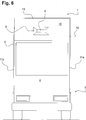
Die
Das Luftkissen
Das Zugfahrzeug
An einer Rückwand
Das Luftkissen
Sobald das Zugfahrzeug
Die
Die
Aufgrund der vollflächigen Abdeckung der Rückwand
Die
Die mittig an der Rückwand
Das Befüllen des Luftkissens
Hierdurch ist es jedoch notwendig, für eine Entlüftung des Luftkissens
Ein Öffnen der Abblasventile
Die
In der
Um im Fahrbetrieb einen ausreichenden Staudruck bereitstellen zu können, weist der in der Fahrzeuglängsachse ausgerichtete Füllkanal
Die
Die Ausführungsform gemäß
Gemäß der Ausführungsform in
Das Luftleitelement
Der Spoiler
Das Befüllen des Luftkissens
BezugszeichenlisteLIST OF REFERENCE NUMBERS
- 11
- Luftleitelementair guide
- 22
- Spaltgap
- 33
- Zugfahrzeugtowing vehicle
- 44
- Anhängerfahrzeugtrailers
- 55
- Luftkissenair cushion
- 66
- Füllkanalfilling channel
- 6a6a
- Verteilungskanaldistribution channel
- 77
- Luftkissen abgewandte Seite FüllkanalAir cushion facing away from filling channel
- 88th
- LufteintrittsöffnungAir inlet opening
- 99
- Aufbau ZugfahrzeugConstruction of towing vehicle
- 1010
- Dachwandroof wall
- 11a, b11a, b
- SeitenwandSide wall
- 1212
- Querschnittskontur AufbauCross-sectional contour structure
- 13a–c13a-c
- Luftkammernair chambers
- 1414
- kammerbildender Konuschamber-forming cone
- 1515
- Tragspangensupport braces
- 1616
- Rückschlagventilcheck valve
- 1717
- Abblasventilblow-off valve
- 1818
- Spoilerspoiler
- 1919
- vorderes Ende Spoilerfront end spoiler
- 2020
- Sattelkupplungfifth wheel
- 2121
- VersorgungskonsoleService Head
- 2222
- Rückwand Aufbau ZugfahrzeugRear wall structure towing vehicle
- 2323
- Dachwand AnhängerfahrzeugRoof wall trailer vehicle
- 2424
- Frontseite AnhängerfahrzeugFront trailer vehicle
- 25 25
- Anströmseite ZugfahrzeugInflow side towing vehicle
- 2626
- Versorgungsleitungsupply line
- FF
- Fahrtrichtungdirection of travel
- WW
- RestspaltmaßRestspaltmaß
ZITATE ENTHALTEN IN DER BESCHREIBUNG QUOTES INCLUDE IN THE DESCRIPTION
Diese Liste der vom Anmelder aufgeführten Dokumente wurde automatisiert erzeugt und ist ausschließlich zur besseren Information des Lesers aufgenommen. Die Liste ist nicht Bestandteil der deutschen Patent- bzw. Gebrauchsmusteranmeldung. Das DPMA übernimmt keinerlei Haftung für etwaige Fehler oder Auslassungen.This list of the documents listed by the applicant has been generated automatically and is included solely for the better information of the reader. The list is not part of the German patent or utility model application. The DPMA assumes no liability for any errors or omissions.
Zitierte PatentliteraturCited patent literature
- US 3711146 [0004] US 3711146 [0004]
- US 3834752 [0005] US 3834752 [0005]
Claims (10)
Priority Applications (10)
| Application Number | Priority Date | Filing Date | Title |
|---|---|---|---|
| DE102012201219.2A DE102012201219B4 (en) | 2012-01-27 | 2012-01-27 | Air control element |
| CA2861144A CA2861144C (en) | 2012-01-27 | 2013-01-07 | Air guiding element |
| PL13700277.0T PL2807072T3 (en) | 2012-01-27 | 2013-01-07 | Air guiding element |
| RU2014134841/11A RU2573529C1 (en) | 2012-01-27 | 2013-01-07 | Air conducting element |
| PCT/EP2013/050154 WO2013110487A1 (en) | 2012-01-27 | 2013-01-07 | Air guiding element |
| ES13700277.0T ES2573834T3 (en) | 2012-01-27 | 2013-01-07 | Air conducting element |
| US14/374,060 US9248873B2 (en) | 2012-01-27 | 2013-01-07 | Air guiding element |
| AU2013211779A AU2013211779B2 (en) | 2012-01-27 | 2013-01-07 | Air guiding element |
| EP13700277.0A EP2807072B1 (en) | 2012-01-27 | 2013-01-07 | Air guiding element |
| BR112014018037-7A BR112014018037B1 (en) | 2012-01-27 | 2013-01-07 | AIR GUIDING ELEMENT FOR IMPROVING FLOW OVER A GAP BETWEEN A TRACTOR VEHICLE AND A TRAILER VEHICLE |
Applications Claiming Priority (1)
| Application Number | Priority Date | Filing Date | Title |
|---|---|---|---|
| DE102012201219.2A DE102012201219B4 (en) | 2012-01-27 | 2012-01-27 | Air control element |
Publications (2)
| Publication Number | Publication Date |
|---|---|
| DE102012201219A1 true DE102012201219A1 (en) | 2013-08-01 |
| DE102012201219B4 DE102012201219B4 (en) | 2020-11-19 |
Family
ID=47559469
Family Applications (1)
| Application Number | Title | Priority Date | Filing Date |
|---|---|---|---|
| DE102012201219.2A Active DE102012201219B4 (en) | 2012-01-27 | 2012-01-27 | Air control element |
Country Status (10)
| Country | Link |
|---|---|
| US (1) | US9248873B2 (en) |
| EP (1) | EP2807072B1 (en) |
| AU (1) | AU2013211779B2 (en) |
| BR (1) | BR112014018037B1 (en) |
| CA (1) | CA2861144C (en) |
| DE (1) | DE102012201219B4 (en) |
| ES (1) | ES2573834T3 (en) |
| PL (1) | PL2807072T3 (en) |
| RU (1) | RU2573529C1 (en) |
| WO (1) | WO2013110487A1 (en) |
Families Citing this family (5)
| Publication number | Priority date | Publication date | Assignee | Title |
|---|---|---|---|---|
| US9637183B2 (en) * | 2015-01-26 | 2017-05-02 | Trailstar International, Inc. | Aerodynamic device for a vehicle |
| US9550535B2 (en) * | 2015-04-17 | 2017-01-24 | General Electric Company | Aerodynamic control system and method |
| US11142264B2 (en) * | 2015-11-20 | 2021-10-12 | David Connors | Draft turbulence reduction system and method |
| US10933894B2 (en) * | 2016-04-16 | 2021-03-02 | Mircea Toma | System for loading and unloading moving vehicles |
| DE102016008120A1 (en) * | 2016-07-01 | 2018-01-04 | Man Truck & Bus Ag | Technology for circulating air around a semitrailer |
Citations (5)
| Publication number | Priority date | Publication date | Assignee | Title |
|---|---|---|---|---|
| US3711146A (en) | 1970-07-29 | 1973-01-16 | White Motor Corp | Streamlined vehicle configuration |
| US3834752A (en) | 1973-01-18 | 1974-09-10 | N Cook | Vehicle space closing means |
| US4978162A (en) * | 1989-11-29 | 1990-12-18 | Labbe Francois P | Drag reducer for rear end of vehicle |
| DE4021337A1 (en) * | 1990-07-04 | 1992-01-09 | Anton Dipl Ing Dr Lechner | DEVICE FOR REDUCING THE FLOW RESISTANCE OF A COMMERCIAL VEHICLE |
| DE102008006365A1 (en) * | 2008-01-28 | 2009-07-30 | Maha Maschinenbau Haldenwang Gmbh & Co. Kg | Air resistance reducing device for e.g. lorry-trailer, has covering element exhibiting tapering form in flow direction of medium that is passed to vehicle, where tapered area lies within elevation surface |
Family Cites Families (10)
| Publication number | Priority date | Publication date | Assignee | Title |
|---|---|---|---|---|
| FR2451852A1 (en) * | 1979-03-20 | 1980-10-17 | Piquilloud Pierre | Fairing to reduce road vehicle air resistance - inflates to tension aerodynamic non flexible cover held by beading in roof fixings |
| DE3151574A1 (en) * | 1981-12-28 | 1983-07-14 | Stromeyer Ingenieurbau GmbH, 7750 Konstanz | Vehicle with box-like superstructure |
| US4702509A (en) * | 1986-05-27 | 1987-10-27 | Elliott Sr Morris C | Long-haul vehicle streamline apparatus |
| US5000508A (en) * | 1990-03-21 | 1991-03-19 | Norman P. Woods | Wind drag reduction device for vehicles |
| US7216923B2 (en) * | 2004-11-12 | 2007-05-15 | Paccar Inc | Systems and methods for reducing the aerodynamic drag on vehicles |
| ITMI20061177A1 (en) * | 2006-06-20 | 2007-12-21 | Iveco Spa | COMPLETE CLOSING SYSTEM OF THE SPACE BETWEEN THE CAB AND THE SEMI-TRAILER OF AN INDUSTRIAL OR COMMERCIAL VEHICLE, TO IMPROVE THE VEHICLE'S AERODYNAMICS |
| US8196993B2 (en) * | 2009-02-06 | 2012-06-12 | Paccar Inc | Drag reducing deflector |
| US8100460B2 (en) * | 2009-03-02 | 2012-01-24 | GM Global Technology Operations LLC | Extendable air control dam for vehicle |
| GB2475032A (en) | 2009-09-29 | 2011-05-11 | Andy Mcgarrie | An inflatable aerodynamic device for streamlining on a vehicle |
| DE102010027715A1 (en) * | 2010-07-20 | 2012-01-26 | Daimler Ag | Wind guiding device for trailer lorry, has wind guiding element covering intermediate space between driving cab and semi trailer, and comprising container that is filled with air and designed such that air is pumped out from container |
-
2012
- 2012-01-27 DE DE102012201219.2A patent/DE102012201219B4/en active Active
-
2013
- 2013-01-07 PL PL13700277.0T patent/PL2807072T3/en unknown
- 2013-01-07 WO PCT/EP2013/050154 patent/WO2013110487A1/en active Application Filing
- 2013-01-07 AU AU2013211779A patent/AU2013211779B2/en active Active
- 2013-01-07 CA CA2861144A patent/CA2861144C/en active Active
- 2013-01-07 RU RU2014134841/11A patent/RU2573529C1/en active
- 2013-01-07 ES ES13700277.0T patent/ES2573834T3/en active Active
- 2013-01-07 US US14/374,060 patent/US9248873B2/en active Active
- 2013-01-07 EP EP13700277.0A patent/EP2807072B1/en active Active
- 2013-01-07 BR BR112014018037-7A patent/BR112014018037B1/en active IP Right Grant
Patent Citations (5)
| Publication number | Priority date | Publication date | Assignee | Title |
|---|---|---|---|---|
| US3711146A (en) | 1970-07-29 | 1973-01-16 | White Motor Corp | Streamlined vehicle configuration |
| US3834752A (en) | 1973-01-18 | 1974-09-10 | N Cook | Vehicle space closing means |
| US4978162A (en) * | 1989-11-29 | 1990-12-18 | Labbe Francois P | Drag reducer for rear end of vehicle |
| DE4021337A1 (en) * | 1990-07-04 | 1992-01-09 | Anton Dipl Ing Dr Lechner | DEVICE FOR REDUCING THE FLOW RESISTANCE OF A COMMERCIAL VEHICLE |
| DE102008006365A1 (en) * | 2008-01-28 | 2009-07-30 | Maha Maschinenbau Haldenwang Gmbh & Co. Kg | Air resistance reducing device for e.g. lorry-trailer, has covering element exhibiting tapering form in flow direction of medium that is passed to vehicle, where tapered area lies within elevation surface |
Also Published As
| Publication number | Publication date |
|---|---|
| ES2573834T3 (en) | 2016-06-10 |
| BR112014018037B1 (en) | 2021-11-23 |
| PL2807072T3 (en) | 2016-10-31 |
| US9248873B2 (en) | 2016-02-02 |
| WO2013110487A1 (en) | 2013-08-01 |
| AU2013211779B2 (en) | 2016-07-28 |
| DE102012201219B4 (en) | 2020-11-19 |
| CA2861144A1 (en) | 2013-08-01 |
| RU2573529C1 (en) | 2016-01-20 |
| BR112014018037A8 (en) | 2017-07-11 |
| CA2861144C (en) | 2017-09-19 |
| EP2807072A1 (en) | 2014-12-03 |
| US20140361579A1 (en) | 2014-12-11 |
| AU2013211779A1 (en) | 2014-07-24 |
| BR112014018037A2 (en) | 2017-06-20 |
| EP2807072B1 (en) | 2016-04-13 |
Similar Documents
| Publication | Publication Date | Title |
|---|---|---|
| EP2509850B1 (en) | Air conducting system | |
| EP2807072B1 (en) | Air guiding element | |
| EP3263428B1 (en) | Technique for air circulation of a semitrailer | |
| DE102008037084A1 (en) | Aerodynamic attachment for lower base of motor vehicle, is formed as flat, plate shaped component, which is extended parallel to vehicle longitudinal axis continuously over bigger part of vehicle length | |
| DE102013008593A1 (en) | Cabover utility vehicle, in particular cab-over-truck, with temporary front and shape-variable, in particular nose-shaped and dome-shaped adjustable and retrofitted air ducts | |
| DE102008059692A1 (en) | Pneumatic front spoiler device for motor vehicle, particularly omnibus, has fixing section, air guiding section and development section, where sections are arranged one after another | |
| DE19640965A1 (en) | Device for reducing air resistance of goods vehicle | |
| EP1897769B1 (en) | Device for removal of rainwater etc. from vehicle tarpaulins | |
| DE102008006365A1 (en) | Air resistance reducing device for e.g. lorry-trailer, has covering element exhibiting tapering form in flow direction of medium that is passed to vehicle, where tapered area lies within elevation surface | |
| DE102015210500B4 (en) | Air guiding element for reducing the air resistance of a truck | |
| DE202018104838U1 (en) | Automotive spoiler device | |
| DE102014018850A1 (en) | Air guiding device for a commercial vehicle | |
| DE102015210502B4 (en) | Air guiding element for reducing the air resistance of a truck | |
| DE19953983A1 (en) | Front end for street vehicle has cover sector able to be deformed into aerodynamic shape | |
| DE102011112245A1 (en) | Longitudinal beam covering e.g. longitudinal support panel has covering element that is elastically deformed such that in extended state it acts as stone impact protection for surrounding portion | |
| DE202013004691U1 (en) | Front-link utility vehicle, in particular front-wheel drive truck, with front side temporarily and shape-variable, in particular nose-shaped and dome-shaped adjustable and retrofitted air ducts | |
| DE202018101555U1 (en) | Motor vehicle spoiler and motor vehicle | |
| DE102015210501B4 (en) | Diffuser with antenna | |
| EP4308439A1 (en) | Semipermeable wind deflector system | |
| DE3151574A1 (en) | Vehicle with box-like superstructure | |
| DE102010046960A1 (en) | Wind guiding device for use in e.g. articulated lorry, has wind guiding elements comprising container that is fillable with medium, where elements are adjustable between two positions by introducing and/or removing medium | |
| DE102014006074A1 (en) | Commercial vehicle with a construction | |
| DE102021106406A1 (en) | Method and system for controlling a cover and truck-trailer combination | |
| DE102018220959A1 (en) | Motor vehicle with air guiding device downstream of the wheel axles | |
| DE102018220961A1 (en) | Motor vehicle with air guide upstream of the side mirrors |
Legal Events
| Date | Code | Title | Description |
|---|---|---|---|
| R012 | Request for examination validly filed | ||
| R016 | Response to examination communication | ||
| R016 | Response to examination communication | ||
| R016 | Response to examination communication | ||
| R016 | Response to examination communication | ||
| R081 | Change of applicant/patentee |
Owner name: JOST-WERKE DEUTSCHLAND GMBH, DE Free format text: FORMER OWNER: JOST-WERKE GMBH, 63263 NEU-ISENBURG, DE |
|
| R082 | Change of representative |
Representative=s name: MEHLER ACHLER PATENTANWAELTE PARTNERSCHAFT MBB, DE |
|
| R079 | Amendment of ipc main class |
Free format text: PREVIOUS MAIN CLASS: B62D0037020000 Ipc: B62D0035000000 |
|
| R018 | Grant decision by examination section/examining division | ||
| R020 | Patent grant now final | ||
| R082 | Change of representative |
Representative=s name: WSL PATENTANWAELTE PARTNERSCHAFT MBB, DE |