DE102012104927A1 - Thermoelectric module and method of operation - Google Patents
Thermoelectric module and method of operation Download PDFInfo
- Publication number
- DE102012104927A1 DE102012104927A1 DE201210104927 DE102012104927A DE102012104927A1 DE 102012104927 A1 DE102012104927 A1 DE 102012104927A1 DE 201210104927 DE201210104927 DE 201210104927 DE 102012104927 A DE102012104927 A DE 102012104927A DE 102012104927 A1 DE102012104927 A1 DE 102012104927A1
- Authority
- DE
- Germany
- Prior art keywords
- wall
- thermoelectric
- heat flow
- flow direction
- compressive stress
- Prior art date
- Legal status (The legal status is an assumption and is not a legal conclusion. Google has not performed a legal analysis and makes no representation as to the accuracy of the status listed.)
- Withdrawn
Links
Images


Classifications
-
- H—ELECTRICITY
- H10—SEMICONDUCTOR DEVICES; ELECTRIC SOLID-STATE DEVICES NOT OTHERWISE PROVIDED FOR
- H10N—ELECTRIC SOLID-STATE DEVICES NOT OTHERWISE PROVIDED FOR
- H10N10/00—Thermoelectric devices comprising a junction of dissimilar materials, i.e. devices exhibiting Seebeck or Peltier effects
- H10N10/10—Thermoelectric devices comprising a junction of dissimilar materials, i.e. devices exhibiting Seebeck or Peltier effects operating with only the Peltier or Seebeck effects
- H10N10/13—Thermoelectric devices comprising a junction of dissimilar materials, i.e. devices exhibiting Seebeck or Peltier effects operating with only the Peltier or Seebeck effects characterised by the heat-exchanging means at the junction
-
- H—ELECTRICITY
- H10—SEMICONDUCTOR DEVICES; ELECTRIC SOLID-STATE DEVICES NOT OTHERWISE PROVIDED FOR
- H10N—ELECTRIC SOLID-STATE DEVICES NOT OTHERWISE PROVIDED FOR
- H10N10/00—Thermoelectric devices comprising a junction of dissimilar materials, i.e. devices exhibiting Seebeck or Peltier effects
- H10N10/10—Thermoelectric devices comprising a junction of dissimilar materials, i.e. devices exhibiting Seebeck or Peltier effects operating with only the Peltier or Seebeck effects
- H10N10/17—Thermoelectric devices comprising a junction of dissimilar materials, i.e. devices exhibiting Seebeck or Peltier effects operating with only the Peltier or Seebeck effects characterised by the structure or configuration of the cell or thermocouple forming the device
-
- H—ELECTRICITY
- H10—SEMICONDUCTOR DEVICES; ELECTRIC SOLID-STATE DEVICES NOT OTHERWISE PROVIDED FOR
- H10N—ELECTRIC SOLID-STATE DEVICES NOT OTHERWISE PROVIDED FOR
- H10N10/00—Thermoelectric devices comprising a junction of dissimilar materials, i.e. devices exhibiting Seebeck or Peltier effects
- H10N10/10—Thermoelectric devices comprising a junction of dissimilar materials, i.e. devices exhibiting Seebeck or Peltier effects operating with only the Peltier or Seebeck effects
Landscapes
- Cooling Or The Like Of Semiconductors Or Solid State Devices (AREA)
- Air-Conditioning For Vehicles (AREA)
- Measuring Temperature Or Quantity Of Heat (AREA)
- Electromechanical Clocks (AREA)
Abstract
Die vorliegende Erfindung ist auf ein Thermoelektrisches Modul (1) und ein Verfahren zum Betrieb gerichtet. Das thermoelektrische Modul (1) weist zumindest eine erste Wandung (2) und eine gegenüberliegend angeordnete zweite Wandung (3) sowie dazwischen angeordnete Elemente (4) aus thermoelektrischem Material (5) auf. Weiterhin ist ein Füllmaterial (6) vorgesehen, durch das alle Elemente (4) voneinander beabstandet sind, und eine Hauptwärmestromrichtung (8), die von der ersten Wandung (2) hin zur zweiten Wandung (3) verläuft.The present invention is directed to a thermoelectric module (1) and a method of operation. The thermoelectric module (1) has at least one first wall (2) and an oppositely arranged second wall (3) and interposed elements (4) of thermoelectric material (5). Furthermore, a filling material (6) is provided, by which all the elements (4) are spaced apart, and a main heat flow direction (8) extending from the first wall (2) towards the second wall (3).
Description
Die vorliegende Erfindung betrifft ein thermoelektrisches Modul und ein Verfahren zum Betrieb eines thermoelektrischen Moduls. The present invention relates to a thermoelectric module and a method for operating a thermoelectric module.
Thermoelektrische Module können einzeln oder in einer Mehrzahl als thermoelektrischer Generator eingesetzt werden, der aus einem Temperaturpotential und dem daraus resultierenden Wärmestrom elektrische Energie erzeugt. Die Erzeugung der elektrischen Energie erfolgt aufgrund des sogenannten Seebeck-Effekts. Thermoelektrische Module sind aus elektrisch miteinander verschalteten p-dotierten und n-dotierten thermoelektrischen Materialien aufgebaut. Die thermoelektrischen Materialien weisen eine sogenannte Heißseite und eine gegenüberliegend angeordnete Kaltseite auf, über die sie jeweils elektrisch leitend wechselweise mit benachbart angeordneten weiteren thermoelektrischen Materialien verbunden sind. Die Heißseite ist dabei mit einer Wandung eines thermoelektrischen Moduls wärmeleitend verbunden, die mit einem heißen Medium beaufschlagt wird. Entsprechend ist die Kaltseite des thermoelektrischen Materials mit einer anderen Wandung des thermoelektrischen Moduls in wärmeleitender Verbindung, die mit einem kalten Medium beaufschlagt ist. Thermoelectric modules can be used individually or in a plurality as a thermoelectric generator, which generates electrical energy from a temperature potential and the resulting heat flow. The generation of electrical energy is due to the so-called Seebeck effect. Thermoelectric modules are constructed of electrically interconnected p-doped and n-doped thermoelectric materials. The thermoelectric materials have a so-called hot side and an oppositely arranged cold side, via which they are each electrically conductively connected alternately with adjacently arranged further thermoelectric materials. The hot side is thermally conductively connected to a wall of a thermoelectric module, which is acted upon by a hot medium. Accordingly, the cold side of the thermoelectric material with another wall of the thermoelectric module in a thermally conductive compound, which is acted upon by a cold medium.
Derartige thermoelektrische Generatoren kommen insbesondere in Kraftfahrzeugen zum Einsatz, aber auch in anderen technischen Gebieten, in denen ein Temperaturpotential durch die Anordnung von thermoelektrischen Generatoren zur Erzeugung elektrischer Energie ausgenutzt werden kann. Such thermoelectric generators are used in particular in motor vehicles, but also in other technical fields in which a temperature potential can be exploited by the arrangement of thermoelectric generators for generating electrical energy.
Bei dem Einsatz von thermoelektrischen Generatoren wird häufig ein Abfall der Effizienz hinsichtlich der Umwandlung von thermischer Energie in elektrische Energie über die Laufzeit des thermoelektrischen Generators beobachtet. Diese, während des Betriebs auftretende Verschleißerscheinung, kann insbesondere darauf zurückgeführt werden, dass sich die Verbindungen zwischen thermoelektrischem Material und weiteren Verbindungsschichten hin zu einer ersten Wandung und/oder zu einer zweiten Wandung eines thermoelektrischen Moduls zunehmend verschlechtern. Diese Beeinträchtigungen der wärmeleitenden und/oder elektrisch leitenden Verbindungen werden insbesondere dadurch hervorgerufen, dass das thermoelektrische Modul regelmäßig wechselnden oder variierenden Temperaturen und Temperaturpotentialen ausgesetzt wird. Das thermoelektrische Modul wird entsprechend durch wechselnde Wärmeausdehnungen und resultierende Wärmespannungen belastet. Zudem verstärken unterschiedliche Wärmeausdehnungskoeffizienten in den einzelnen Verbindungsschichten diese Beanspruchungen. With the use of thermoelectric generators, a drop in the efficiency with regard to the conversion of thermal energy into electrical energy over the term of the thermoelectric generator is frequently observed. This wear phenomenon occurring during operation can be attributed, in particular, to the fact that the connections between the thermoelectric material and further connecting layers towards a first wall and / or to a second wall of a thermoelectric module increasingly deteriorate. These impairments of the heat-conducting and / or electrically conductive connections are in particular caused by the fact that the thermoelectric module is exposed to regularly changing or varying temperatures and temperature potentials. The thermoelectric module is loaded accordingly by changing thermal expansions and resulting thermal stresses. In addition, different thermal expansion coefficients in the individual bonding layers reinforce these stresses.
Aufgabe der vorliegenden Erfindung ist es demnach, die mit Bezug auf den Stand der Technik geschilderten Probleme zumindest teilweise zu lösen. Insbesondere soll ein thermoelektrisches Modul angegeben werden, das eine gleichmäßige hohe Effizienz bei der Umwandlung von thermischer Energie in elektrische Energie über eine lange Laufzeit aufweist. Darüber hinaus soll ein Verfahren zum Betrieb eines thermoelektrischen Moduls angegeben werden, das ebenfalls eine verlängerte Laufzeit eines thermoelektrischen Moduls ermöglicht, ohne dass die Effizienz in zunehmendem Maße verringert wird. Object of the present invention is therefore to solve the problems described with reference to the prior art, at least partially. In particular, a thermoelectric module is to be given, which has a uniform high efficiency in the conversion of thermal energy into electrical energy over a long period. In addition, a method for operating a thermoelectric module is to be given, which also allows a prolonged running time of a thermoelectric module, without the efficiency is increasingly reduced.
Diese Aufgaben werden gelöst mit einem thermoelektrischen Modul gemäß den Merkmalen des Patentanspruchs 1 oder des Patentanspruchs 2 und durch ein Verfahren zum Betrieb eines thermoelektrischen Moduls gemäß Patentanspruch 7. Vorteilhafte Ausgestaltungen der Erfindung sind in den abhängig formulierten Patentansprüchen angegeben. Es ist darauf hinzuweisen, dass die in den Patentansprüchen einzeln aufgeführten Merkmale in beliebiger, technologisch sinnvoller Weise miteinander kombiniert werden können und weitere Ausgestaltungen der Erfindung aufzeigen. Die Beschreibung, insbesondere im Zusammenhang mit den Figuren, erläutert die Erfindung weiter und führt ergänzende Ausführungsbeispiele der Erfindung an. Es ist weiter darauf hinzuweisen, dass die in Bezug auf das thermoelektrische Modul beschriebenen Ausgestaltungen gleichermaßen in technisch sinnvoller Weise auf das Verfahren zum Betrieb eines thermoelektrischen Moduls anwendbar sind und umgekehrt. These objects are achieved with a thermoelectric module according to the features of
Das erfindungsgemäße thermoelektrische Modul weist zumindest eine erste Wandung und eine gegenüberliegend angeordnete zweite Wandung sowie dazwischen angeordnete Elemente aus thermoelektrischem Material auf, die elektrisch leitend miteinander verbunden sind. Weiter ist ein Füllmaterial vorgesehen, durch das alle Elemente voneinander beabstandet sind. Eine Hauptwärmestromrichtung verläuft dabei von einer, durch die erste Wandung gebildeten Heißseite hin zur zweiten Wandung. Es ist vorgesehen, dass im Betrieb des thermoelektrischen Moduls, zumindest in einem Temperaturbereich zwischen 50 und 600 °C [Grad Celsius] an der Heißseite, eine auf die Elemente in Hauptwärmestromrichtung einwirkende zweite Druckspannung zumindest eine erste Grenzspannung nicht überschreitet oder zumindest eine zweite Grenzspannung nicht überschreitet. Die erste Grenzspannung ist eine (temperaturabhängige) Eigenschaft der Elemente aus thermoelektrischem Material, bei deren Überschreitung eine Querkontraktion des eingesetzten thermoelektrischen Materials einsetzt. Die zweite Grenzspannung ist eine (temperaturabhängige) Eigenschaft der Elemente aus thermoelektrischem Material, bei deren Überschreitung eine plastische Verformung des eingesetzten thermoelektrischen Materials einsetzt. The thermoelectric module according to the invention has at least a first wall and an oppositely disposed second wall and interposed therebetween elements made of thermoelectric material, which are electrically conductively connected to each other. Further, a filler material is provided, by which all elements are spaced from each other. A main heat flow direction extends from a hot side formed by the first wall to the second wall. It is envisaged that during operation of the thermoelectric module, at least in a temperature range between 50 and 600 ° C [degrees Celsius] on the hot side, a second compressive stress acting on the elements in the main heat flow direction does not exceed at least a first limit voltage or at least a second limit voltage exceeds. The first limit voltage is a (temperature-dependent) property of the elements made of thermoelectric material, which, when exceeded, causes a transverse contraction of the thermoelectric material used. The second limit voltage is a (temperature-dependent) property of the elements made of thermoelectric material, which, if exceeded, causes a plastic deformation of the thermoelectric material used.
Insbesondere gilt, dass wenn die zweite Grenzspannung erreicht wird, bereits eine Querkontraktion des thermoelektrischen Materials eingesetzt hat. In particular, when the second threshold voltage is reached, a transverse contraction of the thermoelectric material has already begun.
Das weitere erfindungsgemäße thermoelektrische Modul weist zumindest eine erste Wandung und eine gegenüberliegend angeordnete zweite Wandung sowie dazwischen angeordnete Elemente aus thermoelektrischem Material auf, wobei die thermoelektrischen Materialien elektrisch leitend miteinander verbunden sind. Weiterhin ist ein Füllmaterial vorgesehen, durch das alle Elemente voneinander beabstandet sind. Eine Hauptwärmestromrichtung verläuft ausgehend von der ersten Wandung hin zur zweiten Wandung. Das thermoelektrische Modul ist derart durch zumindest eine Druckkraft verspannt, dass eine erste Druckspannung quer zur Hauptwärmestromrichtung, zumindest in einem Bereich, in dem ein Temperaturpotential zwischen erster Wandung und zweiter Wandung mindestens 50 Kelvin, insbesondere mindestens 200 Kelvin beträgt, mindestens 50 % einer zweiten Druckspannung in Hauptwärmestromrichtung beträgt, insbesondere mindestens 75 %, und bevorzugt mindestens so groß ist wie die zweite Druckspannung (größer 100 %). Insbesondere wirkt die erste Druckspannung (und bevorzugt auch die zweite Druckspannung) dabei auf eine Mehrheit, bevorzugt auf alle, Elemente innerhalb des thermoelektrischen Moduls.The further inventive thermoelectric module has at least a first wall and an oppositely disposed second wall and interposed therebetween elements made of thermoelectric material, wherein the thermoelectric materials are electrically conductively connected to each other. Furthermore, a filling material is provided, by which all elements are spaced from each other. A main heat flow direction extends from the first wall towards the second wall. The thermoelectric module is clamped by at least one compressive force such that a first compressive stress transverse to the main heat flow direction, at least in a region in which a temperature potential between first wall and second wall is at least 50 Kelvin, in particular at least 200 Kelvin, at least 50% of a second compressive stress in the main heat flow direction is, in particular at least 75%, and preferably at least as large as the second compressive stress (greater than 100%). In particular, the first compressive stress (and preferably also the second compressive stress) acts on a majority, preferably on all, elements within the thermoelectric module.
Die vorgenannten erfindungsgemäßen Merkmale können auch mit einander kombiniert vorliegen.The abovementioned features according to the invention can also be combined with one another.
Die vorliegende Erfindung ist auf verschiedene Ausführungen von thermoelektrischen Modulen anwendbar. Hierbei sind insbesondere rohrförmig aufgebaute thermoelektrische Module oder plattenförmig aufgebaute thermoelektrische Module zu nennen, wobei in den rohrförmigen thermoelektrischen Modulen z. B. ringförmige thermoelektrische Materialien eingesetzt werden. The present invention is applicable to various types of thermoelectric modules. In this case, in particular tubular thermoelectric modules or plate-shaped thermoelectric modules are mentioned, wherein in the tubular thermoelectric modules z. B. annular thermoelectric materials are used.
Insbesondere ist die erste Wandung einer Heißseite des thermoelektrischen Moduls zugeordnet, die also von einem heißen Medium (z. B. Abgas) beaufschlagt wird. Entsprechend ist die zweite Wandung des thermoelektrischen Moduls einer Kaltseite zugeordnet, die von einem kalten Medium (z. B. Kühlwasser) beaufschlagt wird. Zwischen heißem Medium und kaltem Medium liegt im Betrieb regelmäßig ein Temperaturpotential vor, insbesondere in einem Bereich von 50 K [Kelvin] bis 600 K. Zwischen erster Wandung und zweiter Wandung sind Elemente aus thermoelektrischem Material angeordnet, wobei die thermoelektrischen Materialien zwei gegenüberliegende Seiten aufweisen, die entsprechend der Heißseite oder der Kaltseite zugewandt sind, so dass sich über das thermoelektrische Material ein Temperaturpotential ausbildet und entsprechend eine Hauptwärmestromrichtung von Heißseite zur Kaltseite bildet. Infolge des Seebeck-Effekts wird aus diesem Temperaturpotential und durch die wechselweise elektrisch leitende Verbindung der n-dotierten und p-dotierten thermoelektrischen Materialien ein elektrischer Strom innerhalb des thermoelektrischen Moduls erzeugt. Der grundsätzliche Aufbau der elektrischen Verschaltung solcher Elemente aus thermoelektrischem Material ist dem Fachmann bekannt, gegebenenfalls können weitere Informationen hierzu aus den Vorveröffentlichungen der Anmelderin entnommen werden.In particular, the first wall is associated with a hot side of the thermoelectric module, which is thus acted upon by a hot medium (eg exhaust gas). Accordingly, the second wall of the thermoelectric module is associated with a cold side, which is acted upon by a cold medium (eg., Cooling water). During operation, a temperature potential is regularly present between the hot medium and the cold medium, in particular in a range from 50 K [Kelvin] to 600 K. Elements of thermoelectric material are arranged between the first wall and the second wall, the thermoelectric materials having two opposite sides, which are respectively facing the hot side or the cold side, so that a temperature potential is formed via the thermoelectric material and correspondingly forms a main heat flow direction from the hot side to the cold side. As a result of the Seebeck effect, an electric current is generated within the thermoelectric module from this temperature potential and through the alternately electrically conductive connection of the n-doped and p-doped thermoelectric materials. The basic structure of the electrical interconnection of such elements made of thermoelectric material is known to the expert, if necessary, further information on this can be found in the prior publications of the applicant.
Das Füllmaterial zwischen den thermoelektrischen Elementen dient einerseits insbesondere der elektrischen Isolierung der benachbart zueinander angeordneten thermoelektrischen Materialien und/oder andererseits zur thermischen Isolierung zwischen Heißseite und Kaltseite, so dass ein Großteil des Wärmestroms über die thermoelektrischen Elemente geführt wird. Damit ist eine effiziente Umwandlung der Wärmeenergie aus dem vorliegenden Temperaturpotential in elektrische Energie möglich.The filling material between the thermoelectric elements serves, on the one hand, in particular for the electrical insulation of the adjacent thermoelectric materials and / or on the other hand for thermal insulation between the hot side and the cold side, so that a large part of the heat flow is passed over the thermoelectric elements. Thus, an efficient conversion of the heat energy from the present temperature potential into electrical energy is possible.
Andererseits ist das Füllmaterial insbesondere dazu vorgesehen, die benachbart zueinander angeordneten thermoelektrischen Materialien voneinander zu beabstanden oder mit anderen Worten auch während allen Betriebsbedingungen auf eine (vorgegebene) Distanz zu halten. Insbesondere ist das Füllmaterial also nicht durch Luft oder ein Vakuum gebildet, sondern durch wenigstens einen Festkörper, der die Position der thermoelektrischen Materialien zueinander dauerhaft fixiert. Zwischen den thermoelektrischen Materialien und der ersten Wandung und/oder der zweiten Wandung und/oder auch zwischen thermoelektrischen Materialien und dem Füllmaterial können weitere Komponenten oder Verbindungsschichten angeordnet sein, die spezifische Aufgaben erfüllen, wie beispielsweise Vermeidung von Korrosion, Erzeugen einer festen (z. B. stoffschlüssigen) Verbindung, Bereitstellen einer elektrischen Leitschicht, Bereitstellen einer wärmeleitenden Schicht, elektrische Isolierung und/oder thermische Isolierung. On the other hand, the filling material is intended, in particular, to space the adjacently arranged thermoelectric materials from one another or, in other words, to keep them at a (predetermined) distance during all operating conditions. In particular, the filling material is thus not formed by air or a vacuum, but by at least one solid which permanently fixes the position of the thermoelectric materials to one another. Between the thermoelectric materials and the first wall and / or the second wall and / or between thermoelectric materials and the filling material, further components or connecting layers can be arranged, which fulfill specific tasks, such as avoiding corrosion, producing a solid (eg cohesive) connection, providing an electrically conductive layer, providing a heat-conducting layer, electrical insulation and / or thermal insulation.
Als Füllmaterial kann insbesondere Glimmer oder eine druckfeste Keramik eingesetzt werden. Bevorzugt wird die Keramik als keramischer Hohlkörper eingesetzt. Weiterhin kann das Füllmaterial in der Form eines Doppel-T-Profils eingesetzt werden. Bevorzugt wird das Füllmaterial in Gestalt einer formsteifen Konstruktion eingesetzt, insbesondere in Form einer Fachwerk-artigen Konstruktion. Die darin vorgesehenen Hohlräume sind insbesondere mit Luft, Gas oder Vakuum ausgefüllt. In particular, mica or a flameproof ceramic can be used as filler material. Preferably, the ceramic is used as a ceramic hollow body. Furthermore, the filler can be used in the form of a double T-profile. Preferably, the filling material is used in the form of a dimensionally stable construction, in particular in the form of a truss-like construction. The cavities provided therein are filled in particular with air, gas or vacuum.
Es wurde nun beobachtet, dass das thermoelektrische Material durch die thermische Beanspruchung infolge des vorliegenden Temperaturpotentials und insbesondere durch die damit verbundenen thermischen Spannungen eine verstärkte Neigung zur Querkontraktion und/oder eine Kriechneigung hat bzw. zu einer plastischen Verformung neigt, die jeweils zu einer Verschlechterung der Verbindung zwischen thermoelektrischem Material und weiteren Verbindungsschichten führt, insbesondere hin zu der ersten Wandung bzw. hin zu der zweiten Wandung. Diese thermischen Spannungen werden insbesondere auch durch Anordnung der thermoelektrischen Materialien in einem weitgehend formstabilen thermoelektrischen Modul hervorgerufen, so dass sich die thermoelektrischen Materialien nur unter Spannung ausdehnen können. It has now been observed that the thermoelectric material due to the thermal stress due to the present Temperature potential and in particular by the associated thermal stresses has an increased tendency to transverse contraction and / or a creep tendency or tends to plastic deformation, which leads to a deterioration of the connection between thermoelectric material and other connecting layers, in particular towards the first wall or to the second wall. These thermal stresses are in particular caused by the arrangement of the thermoelectric materials in a largely dimensionally stable thermoelectric module, so that the thermoelectric materials can expand only under tension.
Diese Kriechneigung/ plastische Verformung kann nun insbesondere dadurch reduziert bzw. verhindert werden, dass das thermoelektrische Modul derart aufgebaut ist, dass zumindest in einem Temperaturbereich zwischen 50 °C und 600 °C [Grad Celsius] an der Heißseite, eine auf die Elemente in Hauptwärmestromrichtung einwirkende zweite Druckspannung eine zweite Grenzspannung nicht überschreitet. Eine zweite Grenzspannung ist die auf die thermoelektrischen Materialien einwirkende Spannung, bei der eine plastische Verformung des eingesetzten thermoelektrischen Materials einsetzt. This creep / plastic deformation can be reduced or prevented in particular by the fact that the thermoelectric module is constructed such that at least in a temperature range between 50 ° C and 600 ° C [degrees Celsius] on the hot side, one on the elements in the main heat flow direction acting second compressive stress does not exceed a second limit voltage. A second threshold voltage is the voltage applied to the thermoelectric materials, which utilizes plastic deformation of the thermoelectric material used.
Die Querkontraktion des thermoelektrischen Materials kann insbesondere dadurch reduziert bzw. verhindert werden, dass das thermoelektrische Modul derart aufgebaut ist, dass zumindest in einem Temperaturbereich zwischen 50 °C und 600 °C [Grad Celsius] an der Heißseite, eine auf die Elemente in Hauptwärmestromrichtung einwirkende zweite Druckspannung eine erste Grenzspannung nicht überschreitet. Eine erste Grenzspannung ist die auf die thermoelektrischen Materialien einwirkende Spannung, bei der bereits eine elastische Verformung des eingesetzten thermoelektrischen Materials einsetzt. The transverse contraction of the thermoelectric material can be reduced or prevented in particular by configuring the thermoelectric module such that at least in a temperature range between 50 ° C. and 600 ° C. [degrees Celsius] on the hot side, one acting on the elements in the main heat flow direction second compressive stress does not exceed a first limit voltage. A first limit voltage is the voltage acting on the thermoelectric materials, in which already uses an elastic deformation of the thermoelectric material used.
Die Querkontraktion ist ein Phänomen der Deformation eines festen Körpers bei annähernd gleichbleibendem Volumen. Sie beschreibt das Verhalten des Festkörpers unter dem Einfluss einer Zugkraft bzw. Druckkraft (hier einer zweiten Druckspannung). In Richtung der Kraft (hier die zweite Druckspannung) reagiert der Körper mit einer Längenänderung (hier Verkürzung in Hauptwärmestromrichtung), senkrecht dazu (in Richtung quer zur Hauptwärmestromrichtung) mit einer Verringerung bzw. Vergrößerung seines Durchmessers oder seiner Dicke (hier Ausdehnung, also Vergrößerung der Dicke des thermoelektrischen Materials). Die Längenänderung bei einachsigem Zug kann im linear-elastischen Bereich durch das vereinfachte Hookesche Gesetz bestimmt werden. Über die Dickenänderung macht das Hookesche Gesetz in seiner vereinfachten Form jedoch keine Aussagen. Insbesondere ist die erste Grenzspannung (deutlich) geringer als die zweite Grenzspannung.The transverse contraction is a phenomenon of deformation of a solid at approximately constant volume. It describes the behavior of the solid under the influence of a tensile force or compressive force (here a second compressive stress). In the direction of the force (here the second compressive stress), the body reacts with a change in length (here shortening in the main heat flow direction), perpendicular thereto (in the direction transverse to the main heat flow direction) with a reduction or increase in its diameter or its thickness (in this case expansion, ie enlargement of the Thickness of the thermoelectric material). The change in length in a uniaxial train can be determined in the linear-elastic range by the simplified Hooke's law. However, Hooke's law in its simplified form makes no statements about the change in thickness. In particular, the first limit voltage is (significantly) less than the second limit voltage.
Für einen solchen Aufbau ist insbesondere das Material für die erste Wandung und/oder die zweite Wandung auf das thermoelektrische Material und/oder das Füllmaterial hinsichtlich Wärmeausdehnung, Wärmeleitung, Festigkeit entsprechend aufeinander abzustimmen. Insbesondere ist ggf. zusätzlich die konstruktive Gestaltung des Aufbaus des thermoelektrischen Moduls anzupassen. Beispielsweise können Dehnelemente vorgesehen sein, die eine elastische Verformung der ersten Wandung und/oder der zweiten Wandung ermöglichen, so dass die auf die Elemente wirkende (zweite) Druckspannung minimiert wird. For such a structure, in particular the material for the first wall and / or the second wall to the thermoelectric material and / or the filler material with respect to thermal expansion, heat conduction, strength to match accordingly. In particular, if necessary, in addition to adapt the structural design of the structure of the thermoelectric module. For example, expansion elements may be provided which allow elastic deformation of the first wall and / or the second wall, so that the (second) compressive stress acting on the elements is minimized.
Die erste und die zweite Grenzspannung sind jeweils insbesondere spezifisch für das eingesetzte thermoelektrische Material und insbesondere abhängig zumindest von der Temperatur des thermoelektrischen Materials. Weiterhin sind die erste und zweite Grenzspannung abhängig von der auf das thermoelektrische Material einwirkenden Spannung, die der Richtung der Ausdehnung (im Fall der ersten/ zweiten Grenzspannung) oder der Richtung der Kriechneigung (im Fall der zweiten Grenzspannung) des thermoelektrischen Materials entgegengesetzt ist. Insbesondere heißt das, dass die erste und zweite Grenzspannung des thermoelektrischen Materials beeinflusst (erhöht) werden können, wenn die auf die thermoelektrischen Materialien wirkende erste Druckspannung erhöht wird. Dies erfolgt insbesondere selbstregulierend, z. B. dadurch, dass sich die Füllmaterialien zwischen den thermoelektrischen Materialien bei Erwärmung stärker in Richtung quer zur Hauptwärmestromrichtung ausdehnen als das thermoelektrische Modul insgesamt. The first and the second limit voltage are each in particular specific for the thermoelectric material used and in particular depending at least on the temperature of the thermoelectric material. Further, the first and second limit voltages are dependent on the stress applied to the thermoelectric material, which is opposite to the direction of expansion (in the case of the first / second limit voltage) or the direction of the creep (in the case of the second limit voltage) of the thermoelectric material. In particular, this means that the first and second limit voltages of the thermoelectric material can be influenced (increased) when the first compressive stress acting on the thermoelectric materials is increased. This is done in particular self-regulating, z. B. in that the filling materials between the thermoelectric materials when heated expand more in the direction transverse to the main heat flow direction than the thermoelectric module as a whole.
Die unten genannten thermoelektrischen Materialien weisen bei den genannten Temperaturen und ohne weitere Druckbeanspruchung (z. B. zusätzlich durch erste Druckspannung) die folgenden zweiten Grenzspannungen auf, bei deren Überschreitung mit einer plastischen Verformung zu rechnen ist:
Gemäß einer weiteren Ausgestaltung des thermoelektrischen Moduls kann die Querkontraktion und/oder die Kriechneigung/ plastische Verformung dadurch reduziert bzw. verhindert werden, dass das thermoelektrische Modul mit zumindest einer Druckkraft beaufschlagt wird, so dass eine erste Druckspannung quer zur Hauptwärmestromrichtung auf die Elemente einwirkt, wobei hier bevorzugt ist, möglichst eine große Anzahl oder sogar alle Elemente mit dieser Druckkraft zu beaufschlagen. Dies erfolgt zumindest in einem Bereich, in dem das genannte Temperaturpotential vorliegt, so dass diese erste Druckspannung dann mindestens 50 % einer zweiten Druckspannung in Hauptwärmestromrichtung beträgt. According to a further embodiment of the thermoelectric module, the transverse contraction and / or the creep / plastic deformation can be reduced or prevented by applying at least one compressive force to the thermoelectric module, so that a first compressive stress acts on the elements transversely to the main heat flow direction Here it is preferred to apply as many or even all elements as possible with this pressure force. This occurs at least in a region in which the said temperature potential is present, so that this first compressive stress is then at least 50% of a second compressive stress in the main heat flow direction.
Die zweite Druckspannung wird insbesondere durch die spaltfreie Anordnung der thermoelektrischen Materialien in einer Richtung von der ersten Wandung hin zu der zweiten Wandung hervorgerufen, also in Hauptwärmestromrichtung. Infolge des Temperaturpotentials kommt es zu einer Wärmeausdehnung der zwischen erster Wandung und zweiter Wandung angeordneten Komponenten des thermoelektrischen Moduls, so dass eine zweite Druckspannung in Hauptwärmestromrichtung entsteht bzw. erhöht wird. Diese zweite Druckspannung wirkt der Wärmeausdehnung der einzelnen Komponenten in Hauptwärmestromrichtung entgegen und führt insbesondere bei dem thermoelektrischen Material zu einer Ausdehnung (durch Querkontraktion) und/ oder zu einer Kriechneigung in einer Richtung quer zur Hauptwärmestromrichtung. Die Querkontraktion und/ oder die Kriechneigung kann überraschend durch Aufbringen zumindest einer ersten Druckspannung quer zur Hauptwärmestromrichtung verringert bzw. vollständig unterbunden werden. Insbesondere sind entsprechend weitere erste Druckspannungen vorzusehen, so dass in alle Richtungen quer zur Hauptwärmestromrichtung diese Querkontraktion und/ oder diese Kriechneigung verringert bzw. vollständig unterbunden wird. Damit wurde auch erstmalig erkannt, dass entgegen der üblichen Ansicht, thermische Ausdehnung mit Wegkompensationsmitteln zu erlauben, beim thermoelektrischen Modul eine Art Druckrahmen für die Elemente zu einer verbesserten Effizienz über die Laufzeit führt. The second compressive stress is caused in particular by the gap-free arrangement of the thermoelectric materials in a direction from the first wall to the second wall, ie in the main heat flow direction. As a result of the temperature potential, thermal expansion of the components of the thermoelectric module arranged between the first wall and the second wall occurs, so that a second compressive stress in the main heat flow direction arises or is increased. This second compressive stress counteracts the thermal expansion of the individual components in the main heat flow direction and, in particular with the thermoelectric material, leads to an expansion (due to transverse contraction) and / or to a creeping tendency in a direction transverse to the main heat flow direction. The transverse contraction and / or the creep tendency can be surprisingly reduced or completely suppressed by applying at least one first compressive stress transversely to the main heat flow direction. In particular, correspondingly further first compressive stresses are to be provided so that this transverse contraction and / or this creeping tendency is reduced or completely prevented in all directions transversely to the main heat flow direction. Thus, it was also recognized for the first time that, contrary to the usual view, to allow thermal expansion with path compensation means, the thermoelectric module leads to a kind of pressure frame for the elements to an improved efficiency over the term.
Eine vorteilhafte Ausgestaltung des thermoelektrischen Moduls ist darauf gerichtet, dass das Füllmaterial zumindest in einem Temperaturbereich von 50 °C bis 600 °C einen größeren thermischen Ausdehnungskoeffizienten aufweist als das thermoelektrische Material. Das Füllmaterial ist zumindest in einer Richtung quer zur Hauptwärmestromrichtung so zwischen den thermoelektrischen Materialien angeordnet, dass sich die thermoelektrischen Materialien über das Füllmaterial (und ggf. über weitere Komponenten oder Verbindungsschichten) gegeneinander abstützen, also insbesondere spaltfrei in dieser Richtung zueinander angeordnet sind. Das Füllmaterial fixiert somit die thermoelektrischen Materialien in ihrer jeweiligen Position zueinander. Durch die Gestaltung des Füllmaterials mit einem größeren thermischen Ausdehnungskoeffizienten als das thermoelektrische Material kann, bei Aufheizung des Füllmaterials und der weiteren Komponenten im thermoelektrischen Modul, eine Druckkraft bzw. eine Druckspannung in einer Richtung quer zur Hauptwärmestromrichtung (erst während des Betriebes) erzeugt oder (signifikant) vergrößert werden. Insbesondere ist dafür eine weitgehend formstabile Auslegung des thermoelektrischen Moduls in dieser Richtung quer zur Hauptwärmestromrichtung sicherzustellen. Die Druckkraft muss dann nicht von außen auf das thermoelektrische Modul so aufgebracht werden, dass die Druckspannung sich entsprechend innerhalb des thermoelektrischen Moduls ausbildet, so dass die meisten (oder alle) Elemente durch eine ausreichende Druckspannung beaufschlagt werden. Stattdessen kann diese Druckspannung so zwischen den meisten (oder allen) Elementen durch das Füllmaterial in Wechselwirkung mit den thermoelektrischen Materialien erzeugt werden. An advantageous embodiment of the thermoelectric module is directed to the fact that the filler at least in a temperature range of 50 ° C to 600 ° C has a larger thermal expansion coefficient than the thermoelectric material. The filling material is arranged at least in one direction transversely to the main heat flow direction between the thermoelectric materials such that the thermoelectric materials are supported against each other via the filling material (and optionally via further components or connecting layers), ie in particular are arranged without gaps in this direction relative to one another. The filler material thus fixes the thermoelectric materials in their respective positions relative to each other. By designing the filling material with a larger coefficient of thermal expansion than the thermoelectric material, when the filling material and the other components in the thermoelectric module are heated, a compressive force or a compressive stress is generated in a direction transverse to the main heat flow direction (only during operation) or (significant ). In particular, a largely dimensionally stable design of the thermoelectric module in this direction is to be ensured transversely to the main heat flow direction. The compressive force must then not be applied from the outside to the thermoelectric module so that the compressive stress is formed accordingly within the thermoelectric module, so that most (or all) elements are acted upon by a sufficient compressive stress. Instead, this compressive stress can thus be generated between most (or all) elements by the filler in interaction with the thermoelectric materials.
Eine weitere vorteilhafte Ausgestaltung des thermoelektrischen Moduls ist darauf gerichtet, dass das Füllmaterial zumindest in einem Temperaturbereich von 50 °C bis 600 °C eine geringere Wärmeleitfähigkeit [Watt / (Meter * Kelvin] aufweist als das thermoelektrische Material. Insbesondere beträgt der Wert der Wärmeleitfähigkeit des Füllmaterials höchstens 10 % des Wertes des thermoelektrischen Materials, bevorzugt höchstens 1 %. A further advantageous embodiment of the thermoelectric module is directed to the fact that the filler has a lower thermal conductivity [watt / (meter * Kelvin] than the thermoelectric material at least in a temperature range of 50 ° C. to 600 ° C. In particular, the value of the thermal conductivity of the Filling material at most 10% of the value of the thermoelectric material, preferably at most 1%.
Eine weitere vorteilhafte Ausgestaltung des thermoelektrischen Moduls sieht vor, dass das Füllmaterial, betrachtet zumindest in einer Richtung parallel zur Hauptwärmestromrichtung, einen Zwischenraum zwischen erster Wandung und zweiter Wandung nicht vollständig ausfüllt. Es ist insbesondere vorteilhaft, dass das Füllmaterial die Position der thermoelektrischen Materialien zueinander fixiert, gleichzeitig aber nicht die gesamte Seitenfläche der thermoelektrischen Materialien, die jeweils den benachbart angeordneten thermoelektrischen Materialien zugewandt ist, bedeckt. Insbesondere werden höchstens 80 %, bevorzugt höchstens 50 % und besonders bevorzugt höchstens 20 % dieser Seitenfläche durch das Füllmaterial mit einer Druckspannung beaufschlagt, wobei das nicht für alle Elemente bzw. thermoelektrischen Materialen eines einzelnen Moduls gleichermaßen gelten muss. Über das Füllmaterial wird die Druckkraft bzw. die Druckspannung auf das thermoelektrische Material übertragen. Durch die entsprechende Anordnung des Füllmaterials kann insbesondere die thermische Isolierung zwischen erster Wandung und zweiter Wandung in besonders vorteilhafter Weise umgesetzt werden und das Füllmaterial muss diese thermische isolierende Eigenschaft nicht zwingend erfüllen. Beispielsweise kann Luft, ein Vakuum oder ein anderer wärmeisolierender Werkstoff zusätzlich zum Füllmaterial eingesetzt werden. A further advantageous embodiment of the thermoelectric module provides that the filling material, viewed in at least one direction parallel to the main heat flow direction, does not completely fill a gap between the first wall and the second wall. It is particularly advantageous that the filler material fixes the position of the thermoelectric materials to each other, but at the same time not the entire side surface of the thermoelectric materials, which faces each of the adjacent arranged thermoelectric materials covered. In particular, at most 80%, preferably at most 50% and particularly preferably at most 20% of this side surface is subjected to a compressive stress by the filling material, which does not have to apply equally to all elements or thermoelectric materials of a single module. The compressive force or the compressive stress is transferred to the thermoelectric material via the filling material. By the appropriate arrangement of the Filler material, in particular, the thermal insulation between the first wall and the second wall can be implemented in a particularly advantageous manner and the filler does not necessarily meet this thermal insulating property. For example, air, a vacuum or other heat-insulating material may be used in addition to the filler material.
Eine vorteilhafte Weiterbildung des thermoelektrischen Moduls ist darauf gerichtet, dass auf einer Kaltseite eine Verspannungsvorrichtung zur Erzeugung der Druckkraft auf das thermoelektrische Modul in einer Richtung quer zur Hauptwärmestromrichtung angeordnet ist. Insbesondere umfasst diese Anordnung eine z. B. mit der zweiten Wandung verbundene Verspannungsvorrichtung. Diese Verspannungsvorrichtung wird insbesondere thermisch isoliert gegenüber der ersten Wandung ausgeführt. Dadurch weist die Verspannungsvorrichtung eine geringe Wärmedehnung trotz des vorliegenden Temperaturpotentials auf und kann die Formstabilität des thermoelektrischen Moduls in einer Richtung quer zur Hauptwärmestromrichtung über den betrachteten Temperaturbereich gewährleisten. Die Verspannungsvorrichtung kann insbesondere eine mechanische oder auch hydraulische Vorrichtung sein. Insbesondere wird sie durch eine besonders formsteife Ausgestaltung der Kaltseite bzw. der zweiten Wandung gebildet, so dass in dem betrachteten Temperaturbereich eine (im Wesentlichen gleichbleibende oder angepasste) Druckkraft gegenüber den thermoelektrischen Materialien und dem Füllmaterial ausgehend von der Verspannungsvorrichtung erzeugt werden kann.An advantageous development of the thermoelectric module is directed to that on a cold side, a bracing device for generating the pressure force on the thermoelectric module is arranged in a direction transverse to the main heat flow direction. In particular, this arrangement comprises a z. B. connected to the second wall bracing device. This bracing device is in particular thermally insulated from the first wall. As a result, the bracing device has a low thermal expansion despite the present temperature potential and can ensure the dimensional stability of the thermoelectric module in a direction transverse to the main heat flow direction over the temperature range under consideration. The bracing device may in particular be a mechanical or even hydraulic device. In particular, it is formed by a particularly rigid design of the cold side or the second wall, so that in the temperature range considered a (substantially constant or adapted) compressive force against the thermoelectric materials and the filler material can be generated starting from the bracing device.
Insbesondere ist eine Verspannungsvorrichtung an der ersten Wandung (Heißseite) (zusätzlich) vorgesehen.In particular, a bracing device is (additionally) provided on the first wall (hot side).
Die Verspannungsvorrichtung kann insbesondere ein elastisch verformbares Element umfassen, das mit stärkerer Verformung eine entsprechend höhere Druckspannung in das thermoelektrische Modul einleiten kann. Beispielsweise kann eine Druckfeder vorgesehen sein, die bei fortlaufender Ausdehnung des thermoelektrischen Moduls, bzw. bei Ausdehnung der Elemente in einer Richtung quer zur Hauptwärmestromrichtung eine entsprechend steigende Druckspannung erzeugt. Durch diese steigende Druckspannung wird eine elastische Ausdehung und/ oder eine plastische Verformung der thermoelektrischen Materialien in einer Richtung quer zur Hauptwärmestromrichtung verringert oder verhindert.The bracing device may in particular comprise an elastically deformable element which can initiate a correspondingly higher compressive stress into the thermoelectric module with greater deformation. For example, a compression spring can be provided, which generates a correspondingly increasing compressive stress in the case of continuous expansion of the thermoelectric module, or in the case of expansion of the elements in a direction transverse to the main heat flow direction. This increasing compressive stress reduces or prevents elastic expansion and / or plastic deformation of the thermoelectric materials in a direction transverse to the main heat flow direction.
Die Erfindung ist weiterhin auf ein Verfahren zum Betrieb eines thermoelektrischen Moduls gerichtet, wobei das thermoelektrische Modul eine erste Wandung und eine zweite Wandung und dazwischen angeordnete Elemente aus thermoelektrischem Material aufweist, die elektrisch leitend miteinander verbunden sind. Im Betrieb des thermoelektrischen Moduls liegt ein Temperaturpotential zwischen erster Wandung und zweiter Wandung vor und entsprechend verläuft eine Hauptwärmestromrichtung von der ersten Wandung hin zu der zweiten Wandung. Das Verfahren zum Betrieb weist zumindest folgende Schritte auf:
- a) Erzeugen eines Temperaturpotentials zwischen erster Wandung und zweiter Wandung;
- b) Aufbringen mindestens einer Druckkraft zur Erzeugung einer ersten Druckspannung quer zur Hauptwärmestromrichtung, wobei die Druckspannung zumindest auf eine Mehrheit der Elemente einwirkt;
- c) Sicherstellen, dass zumindest in einem Betriebsbereich, in dem ein Temperaturpotential zwischen erster Wandung und zweiter Wandung mindestens 50 Kelvin beträgt, die erste Druckspannung mindestens 50 % einer zweiten Druckspannung in Hauptwärmestromrichtung beträgt, insbesondere mindestens 75 % und bevorzugt mindestens so groß ist wie eine zweite Druckspannung in Hauptwärmestromrichtung.
- a) generating a temperature potential between the first wall and the second wall;
- b) applying at least one compressive force for generating a first compressive stress transversely to the main heat flow direction, wherein the compressive stress acts on at least a majority of the elements;
- c) ensure that at least in an operating range in which a temperature potential between the first wall and the second wall is at least 50 Kelvin, the first compressive stress is at least 50% of a second compressive stress in the main heat flow direction, in particular at least 75% and preferably at least as great as one second compressive stress in the main heat flow direction.
Die Ausführungen zum jeweiligen thermoelektrischen Modul gelten entsprechend für das Verfahren zum Betrieb eines thermoelektrischen Moduls und umgekehrt. Insbesondere ist das hier erfindungsgemäß beschriebene Verfahren zum Betrieb des jeweils erfindungsgemäßen thermoelektrischen Moduls geeignet. The remarks on the respective thermoelectric module apply correspondingly to the method for operating a thermoelectric module and vice versa. In particular, the method described here according to the invention for operating the respectively inventive thermoelectric module is suitable.
Das Erzeugen des Temperaturpotentials gemäß Schritt a) umfasst das Beaufschlagen der ersten Wandung mit einem heißen Medium und das Beaufschlagen der zweiten Wandung mit einem kalten Medium. Insbesondere sind ein Abgas oder ein flüssiges Medium als heißes Medium und z. B. Wasser oder eine ähnliche Flüssigkeit, aber auch ein gasförmiges Medium als kaltes Medium vorzusehen. The generation of the temperature potential according to step a) comprises applying the first wall to a hot medium and applying the second wall to a cold medium. In particular, an exhaust gas or a liquid medium as a hot medium and z. As water or a similar liquid, but also provide a gaseous medium as a cold medium.
Schritt b) umfasst das Aufbringen mindestens einer Druckkraft, die insbesondere durch eine Verspannungsvorrichtung von außen auf das thermoelektrische Modul aufgebracht und/oder auch innerhalb des thermoelektrischen Moduls z. B. durch entsprechende Ausdehnungskoeffizienten des thermoelektrischen Materials und des Füllmaterials erzeugt werden kann. Step b) comprises the application of at least one compressive force, which is applied in particular by a bracing device from the outside to the thermoelectric module and / or within the thermoelectric module z. B. can be generated by corresponding expansion coefficients of the thermoelectric material and the filling material.
Das Sicherstellen des Verhältnisses der Druckspannungen gemäß Schritt c) umfasst insbesondere die entsprechende konstruktive Auslegung des thermoelektrischen Moduls bereits vor der Aufnahme des Betriebs. Insbesondere umfasst das Sicherstellen die Kontrolle und entsprechende Einwirkung, so dass die erste und/oder zweite Druckspannung berechnet, gemessen oder in anderer Weise bestimmt und eine entsprechende erste Druckspannung erzeugt wird. Unter „Sicherstellen“ wird insbesondere auch das Überwachen, Einstellen und/oder Anpassen der Druckkraft (ggf. auch während des Betriebes) verstanden.Ensuring the ratio of the compressive stresses according to step c) comprises, in particular, the corresponding structural design of the thermoelectric module even before the start of operation. In particular, the assurance includes the control and corresponding action such that the first and / or second compressive stress is calculated, measured or otherwise determined and a corresponding first compressive stress is generated. By "ensuring" is meant in particular also the monitoring, setting and / or adjusting the pressure force (possibly also during operation).
Gemäß einer vorteilhaften Ausgestaltung des Verfahrens wird die erste Druckspannung quer zur Hauptwärmestromrichtung durch eine äußere Regelung der mindestens einen Druckkraft beeinflusst. Diese äußere Regelung kann z. B. durch eine Verspannungsvorrichtung realisiert werden, durch die eine regelbare mechanische und/oder eine hydraulische Druckkraft erzeugt werden kann.According to an advantageous embodiment of the method, the first compressive stress is influenced transversely to the main heat flow direction by an external control of the at least one pressure force. This external regulation can z. B. can be realized by a bracing device through which a controllable mechanical and / or hydraulic pressure force can be generated.
Gemäß einer vorteilhaften Weiterbildung wird die erste Druckspannung selbstregulierend verändert. Dies kann insbesondere durch eine entsprechende Auslegung der Materialeigenschaften von thermoelektrischem Material und Füllmaterial gewährleistet werden. „Selbstregulierend“ bedeutet hier insbesondere, dass keine aktive, externe Regulierung der Druckspannung erfolgt, sondern insbesondere dass die Konstruktion so ausgelegt ist, dass sich das vorgegebenen Druckspannungsverhältnis während des Betriebes des thermoelektrischen Moduls in unterschiedlichen Temperaturbereichen automatisch bzw. passiv anpasst. In besonders vorteilhafter Weise werden äußere Regelungen und selbstregulierende Maßnahmen miteinander kombiniert. According to an advantageous development, the first compressive stress is changed in a self-regulating manner. This can be ensured in particular by a corresponding design of the material properties of thermoelectric material and filler. "Self-regulating" here means, in particular, that no active, external regulation of the compressive stress takes place, but in particular that the construction is designed so that the predetermined compressive stress ratio adapts automatically or passively during operation of the thermoelectric module in different temperature ranges. In a particularly advantageous manner, external controls and self-regulating measures are combined.
Weiterhin wird ein thermoelektrischer Generator vorgeschlagen, der zumindest zwei erfindungsgemäße thermoelektrische Module aufweist, wobei die thermoelektrischen Module durch eine (insbesondere einzige) Komponente des thermoelektrischen Generators gemeinsam mit zumindest einer Druckkraft zur Erzeugung einer ersten Druckspannung beaufschlagt werden. In besonders vorteilhafter Weise wird also nicht jedes einzelne thermoelektrische Modul eines thermoelektrischen Generators mit einer jeweils einzeln erzeugten Druckkraft beaufschlagt, sondern es ist z. B. eine gemeinsame Verspannungsvorrichtung konstruktiv so ausgelegt, dass mehrere thermoelektrische Module entsprechend gleichzeitig beaufschlagt werden können. Insbesondere können mehrere thermoelektrische Module entsprechend auch hintereinander angeordnet werden, so dass die Druckkraft auch zwischen den thermoelektrischen Modulen übertragen wird.Furthermore, a thermoelectric generator is proposed, which has at least two thermoelectric modules according to the invention, wherein the thermoelectric modules are acted upon by a (in particular only) component of the thermoelectric generator together with at least one pressure force for generating a first compressive stress. In a particularly advantageous manner, therefore, not every single thermoelectric module of a thermoelectric generator is subjected to a pressure force generated individually, but it is z. B. a common bracing device constructively designed so that a plurality of thermoelectric modules can be acted upon accordingly at the same time. In particular, a plurality of thermoelectric modules can also be arranged corresponding to one behind the other, so that the pressure force is also transmitted between the thermoelectric modules.
Weiterhin wird ein Kraftfahrzeug vorgeschlagen, zumindest aufweisend ein erfindungsgemäßes thermoelektrisches Modul oder einen erfindungsgemäßen thermoelektrischen Generator. Dabei können dieses Modul und/oder dieser Generator auch zum Betrieb mit dem erfindungsgemäß beschriebenen Verfahren eingerichtet sein.Furthermore, a motor vehicle is proposed, at least comprising a thermoelectric module according to the invention or a thermoelectric generator according to the invention. In this case, this module and / or this generator can also be set up for operation with the method described according to the invention.
Die Erfindung sowie das technische Umfeld werden nachfolgend anhand der Figuren näher erläutert. Die Figuren zeigen besonders bevorzugte Ausführungsbeispiele, auf die die Erfindung jedoch nicht begrenzt ist. Es zeigen schematisch: The invention and the technical environment will be explained in more detail with reference to FIGS. The figures show particularly preferred embodiments, to which the invention is not limited. They show schematically:
Die thermoelektrischen Materialien
Zwischen der Heißseite
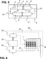
Die in
In
Gezeigt ist hier weiterhin, dass die Seitenflächen
Weiterhin sind hier Zwischenräume
BezugszeichenlisteLIST OF REFERENCE NUMBERS
- 11
- Thermoelektrisches Modul Thermoelectric module
- 22
- Erste Wandung First wall
- 33
- Zweite Wandung Second wall
- 44
- Elemente elements
- 55
- Thermoelektrisches Material Thermoelectric material
- 66
- Füllmaterial filling material
- 77
- Erste Druckspannung First compressive stress
- 88th
- Hauptwärmestromrichtung Main heat flow direction
- 99
- Betriebsbereich operating range
- 1010
- Temperaturpotential temperature potential
- 1111
- Zweite Druckspannung Second compressive stress
- 1212
- Zwischenraum gap
- 1313
- Kaltseite cold side
- 1414
- Verspannungsvorrichtung tensioning device
- 1515
- Druckkraft thrust
- 1616
- Richtung direction
- 1717
- Heißseite hot side
- 1818
- Thermoelektrischer Generator Thermoelectric generator
- 1919
- Komponente component
- 2020
- Kraftfahrzeug motor vehicle
- 2121
- Medium medium
- 2222
- Abgasanlage exhaust system
- 2323
- Isolierung insulation
- 2424
- Verbindung connection
- 2525
- Temperatur temperature
- 2626
- Betriebszeit uptime
- 2727
- Druckspannung compressive stress
- 2828
- Kühlung cooling
- 2929
- Verbrennungskraftmaschine Internal combustion engine
- 3030
- Seite page
- 3131
- Verbindungsschicht link layer
- 3232
- Seitenfläche side surface
- 3333
- Dehnelement expansion element
- 3434
- Erste Grenzspannung First limit voltage
- 3535
- Zweite Grenzspannung Second limit voltage
Claims (11)
Priority Applications (9)
| Application Number | Priority Date | Filing Date | Title |
|---|---|---|---|
| DE201210104927 DE102012104927A1 (en) | 2012-06-06 | 2012-06-06 | Thermoelectric module and method of operation |
| EP13726479.2A EP2859598B1 (en) | 2012-06-06 | 2013-05-24 | Thermoelectric module and method for operating same |
| JP2015515466A JP6173445B2 (en) | 2012-06-06 | 2013-05-24 | Thermoelectric module and operation method thereof |
| PCT/EP2013/060765 WO2013182441A2 (en) | 2012-06-06 | 2013-05-24 | Thermoelectric module and method for operating same |
| CN201380029788.2A CN104335373B (en) | 2012-06-06 | 2013-05-24 | Electrothermal module and its operation method |
| KR1020147035660A KR101657391B1 (en) | 2012-06-06 | 2013-05-24 | Thermoelectric module and method for operating same |
| RU2014154138A RU2630540C2 (en) | 2012-06-06 | 2013-05-24 | Thermoelectric module and method of its operation |
| IN9760DEN2014 IN2014DN09760A (en) | 2012-06-06 | 2014-11-18 | |
| US14/562,949 US20150114440A1 (en) | 2012-06-06 | 2014-12-08 | Thermoelectric module, method for operating the thermoelectric module, thermoelectric generator and motor vehicle |
Applications Claiming Priority (1)
| Application Number | Priority Date | Filing Date | Title |
|---|---|---|---|
| DE201210104927 DE102012104927A1 (en) | 2012-06-06 | 2012-06-06 | Thermoelectric module and method of operation |
Publications (1)
| Publication Number | Publication Date |
|---|---|
| DE102012104927A1 true DE102012104927A1 (en) | 2013-12-12 |
Family
ID=48570100
Family Applications (1)
| Application Number | Title | Priority Date | Filing Date |
|---|---|---|---|
| DE201210104927 Withdrawn DE102012104927A1 (en) | 2012-06-06 | 2012-06-06 | Thermoelectric module and method of operation |
Country Status (9)
| Country | Link |
|---|---|
| US (1) | US20150114440A1 (en) |
| EP (1) | EP2859598B1 (en) |
| JP (1) | JP6173445B2 (en) |
| KR (1) | KR101657391B1 (en) |
| CN (1) | CN104335373B (en) |
| DE (1) | DE102012104927A1 (en) |
| IN (1) | IN2014DN09760A (en) |
| RU (1) | RU2630540C2 (en) |
| WO (1) | WO2013182441A2 (en) |
Cited By (1)
| Publication number | Priority date | Publication date | Assignee | Title |
|---|---|---|---|---|
| DE102014117584B4 (en) * | 2013-12-17 | 2018-10-18 | International Business Machines Corporation | Thermoelectric unit |
Citations (4)
| Publication number | Priority date | Publication date | Assignee | Title |
|---|---|---|---|---|
| US3090206A (en) * | 1960-06-23 | 1963-05-21 | Frank W Anders | Thermoelectric devices and circuits therefor |
| US3607444A (en) * | 1966-12-06 | 1971-09-21 | Siemens Ag | Thermoelectric assembly |
| EP1505662A2 (en) * | 2003-07-25 | 2005-02-09 | Kabushiki Kaisha Toshiba | Thermoelectric device |
| WO2010103977A1 (en) * | 2009-03-09 | 2010-09-16 | 住友化学株式会社 | Thermoelectric conversion module |
Family Cites Families (14)
| Publication number | Priority date | Publication date | Assignee | Title |
|---|---|---|---|---|
| US5056414A (en) * | 1987-10-20 | 1991-10-15 | Nova-Werke Ag | Linear drive with hydraulic amplification |
| JPH08288557A (en) * | 1995-02-17 | 1996-11-01 | Matsushita Electric Works Ltd | Theroelectric conversion device |
| JPH08335722A (en) * | 1995-06-08 | 1996-12-17 | Ngk Insulators Ltd | Thermoelectric conversion module |
| JPH0992890A (en) * | 1995-09-25 | 1997-04-04 | Matsushita Electric Works Ltd | Thermoelectric converter |
| US7273981B2 (en) * | 2001-02-09 | 2007-09-25 | Bsst, Llc. | Thermoelectric power generation systems |
| US6410971B1 (en) | 2001-07-12 | 2002-06-25 | Ferrotec (Usa) Corporation | Thermoelectric module with thin film substrates |
| JP2004063656A (en) * | 2002-07-26 | 2004-02-26 | Toshiba Corp | Thermoelectric converter |
| JP2005127162A (en) * | 2003-10-21 | 2005-05-19 | Toyota Motor Corp | Exhaust heat recovery system |
| JP4266228B2 (en) * | 2006-03-24 | 2009-05-20 | 株式会社東芝 | Thermoelectric conversion module and manufacturing method thereof |
| US20070272292A1 (en) * | 2006-05-24 | 2007-11-29 | Jerrei Lin | Thermal-recycling system for a motor vehicle |
| JP2008270618A (en) * | 2007-04-23 | 2008-11-06 | Toyota Motor Corp | Thermoelectric power generation module |
| JP2008288535A (en) * | 2007-05-21 | 2008-11-27 | Toyota Motor Corp | Thermoelectric power generation module |
| EP2280432A4 (en) * | 2008-05-23 | 2012-10-24 | Murata Manufacturing Co | Thermoelectric conversion module and process for producing thermoelectric conversion module |
| DE102010044803A1 (en) * | 2010-09-09 | 2012-03-15 | Emitec Gesellschaft Für Emissionstechnologie Mbh | Thermoelectric module for a thermoelectric generator of a vehicle with a sealing element |
-
2012
- 2012-06-06 DE DE201210104927 patent/DE102012104927A1/en not_active Withdrawn
-
2013
- 2013-05-24 JP JP2015515466A patent/JP6173445B2/en active Active
- 2013-05-24 EP EP13726479.2A patent/EP2859598B1/en active Active
- 2013-05-24 KR KR1020147035660A patent/KR101657391B1/en active IP Right Grant
- 2013-05-24 WO PCT/EP2013/060765 patent/WO2013182441A2/en active Application Filing
- 2013-05-24 RU RU2014154138A patent/RU2630540C2/en active
- 2013-05-24 CN CN201380029788.2A patent/CN104335373B/en active Active
-
2014
- 2014-11-18 IN IN9760DEN2014 patent/IN2014DN09760A/en unknown
- 2014-12-08 US US14/562,949 patent/US20150114440A1/en not_active Abandoned
Patent Citations (4)
| Publication number | Priority date | Publication date | Assignee | Title |
|---|---|---|---|---|
| US3090206A (en) * | 1960-06-23 | 1963-05-21 | Frank W Anders | Thermoelectric devices and circuits therefor |
| US3607444A (en) * | 1966-12-06 | 1971-09-21 | Siemens Ag | Thermoelectric assembly |
| EP1505662A2 (en) * | 2003-07-25 | 2005-02-09 | Kabushiki Kaisha Toshiba | Thermoelectric device |
| WO2010103977A1 (en) * | 2009-03-09 | 2010-09-16 | 住友化学株式会社 | Thermoelectric conversion module |
Cited By (1)
| Publication number | Priority date | Publication date | Assignee | Title |
|---|---|---|---|---|
| DE102014117584B4 (en) * | 2013-12-17 | 2018-10-18 | International Business Machines Corporation | Thermoelectric unit |
Also Published As
| Publication number | Publication date |
|---|---|
| JP6173445B2 (en) | 2017-08-02 |
| KR101657391B1 (en) | 2016-09-19 |
| WO2013182441A3 (en) | 2014-09-12 |
| JP2015524171A (en) | 2015-08-20 |
| KR20150013326A (en) | 2015-02-04 |
| IN2014DN09760A (en) | 2015-07-31 |
| RU2630540C2 (en) | 2017-09-11 |
| US20150114440A1 (en) | 2015-04-30 |
| EP2859598B1 (en) | 2018-03-21 |
| EP2859598A2 (en) | 2015-04-15 |
| CN104335373B (en) | 2018-04-03 |
| CN104335373A (en) | 2015-02-04 |
| WO2013182441A2 (en) | 2013-12-12 |
| RU2014154138A (en) | 2016-08-10 |
Similar Documents
| Publication | Publication Date | Title |
|---|---|---|
| EP2531705B1 (en) | Thermoelectric generator with integrated preloaded mounting | |
| DE112007002615B4 (en) | Thermoelectric device and thermoelectric module | |
| DE102009013692A1 (en) | Thermoelectric device | |
| DE102011009428A1 (en) | Thermoelectric module with a heat conducting layer | |
| DE202010018101U1 (en) | Thermoelectric generator device | |
| EP2454456A1 (en) | Thermoelectric device comprising tube bundles | |
| WO2010130764A2 (en) | Heat exchanger and method for converting thermal energy of a fluid into electrical energy | |
| WO2009077468A2 (en) | Thermoelectric module and thermoelectric generator | |
| DE102007063196A1 (en) | Thermoelectric generator, has connecting device comprising strapping element that sectionally encloses stack axis, where compressive force exerts on stack axis and is approximately aligned parallel to stack axis | |
| DE102010035152A1 (en) | Semiconductor element and insulating material in ring form for a thermoelectric module | |
| EP2865023A1 (en) | Thermoelectric module, heat exchanger, exhaust gas system and internal combustion engine | |
| DE102013112911A1 (en) | Thermoelectric generator apparatus and method of manufacturing a thermoelectric generator apparatus | |
| DE102015210398A1 (en) | Thermoelectric generator for converting heat of a hot gas stream into electrical energy | |
| EP2664014A2 (en) | Thermoelectric module with means for compensating for a thermal expansion | |
| DE102011005206A1 (en) | Thermoelectrical generator for use in e.g. exhaust gas strand of vehicle, has cover made of ceramic material, connected with main surface of flat tube and designed to seal thermal electrical foil against fluid on side of cover | |
| DE102011012448A1 (en) | Thermoelectric module for a thermoelectric generator of a vehicle | |
| EP2805361B1 (en) | Semiconductor element for use in a thermoelectric module | |
| EP2859598B1 (en) | Thermoelectric module and method for operating same | |
| EP2630671B1 (en) | Semi-conductor elements made of thermoelectric material for use in a thermoelectric module | |
| DE102012105496A1 (en) | Thread with a thermoelectric material and method for producing a component for a thermoelectric module | |
| EP2522040B1 (en) | Device for generating electric energy from a heat-conducting material | |
| DE102015105939A1 (en) | Device for the thermoelectric conversion of thermal energy | |
| DE202010007872U1 (en) | Thermoelectric generator | |
| DE102016208070A1 (en) | Thermoelectric module | |
| DE102016206506A1 (en) | Thermoelectric module |
Legal Events
| Date | Code | Title | Description |
|---|---|---|---|
| R163 | Identified publications notified | ||
| R081 | Change of applicant/patentee |
Owner name: CONTINENTAL AUTOMOTIVE GMBH, DE Free format text: FORMER OWNER: EMITEC GESELLSCHAFT FUER EMISSIONSTECHNOLOGIE MBH, 53797 LOHMAR, DE |
|
| R082 | Change of representative | ||
| R081 | Change of applicant/patentee |
Owner name: CONTINENTAL AUTOMOTIVE GMBH, DE Free format text: FORMER OWNER: CONTINENTAL AUTOMOTIVE GMBH, 30165 HANNOVER, DE |
|
| R082 | Change of representative | ||
| R005 | Application deemed withdrawn due to failure to request examination |