DE102012009421A1 - flow sensor - Google Patents
flow sensor Download PDFInfo
- Publication number
- DE102012009421A1 DE102012009421A1 DE102012009421A DE102012009421A DE102012009421A1 DE 102012009421 A1 DE102012009421 A1 DE 102012009421A1 DE 102012009421 A DE102012009421 A DE 102012009421A DE 102012009421 A DE102012009421 A DE 102012009421A DE 102012009421 A1 DE102012009421 A1 DE 102012009421A1
- Authority
- DE
- Germany
- Prior art keywords
- flow
- flow sensor
- encapsulation
- sensor
- sensor element
- Prior art date
- Legal status (The legal status is an assumption and is not a legal conclusion. Google has not performed a legal analysis and makes no representation as to the accuracy of the status listed.)
- Withdrawn
Links
Images


Classifications
-
- G—PHYSICS
- G01—MEASURING; TESTING
- G01F—MEASURING VOLUME, VOLUME FLOW, MASS FLOW OR LIQUID LEVEL; METERING BY VOLUME
- G01F1/00—Measuring the volume flow or mass flow of fluid or fluent solid material wherein the fluid passes through a meter in a continuous flow
- G01F1/68—Measuring the volume flow or mass flow of fluid or fluent solid material wherein the fluid passes through a meter in a continuous flow by using thermal effects
- G01F1/684—Structural arrangements; Mounting of elements, e.g. in relation to fluid flow
-
- G—PHYSICS
- G01—MEASURING; TESTING
- G01F—MEASURING VOLUME, VOLUME FLOW, MASS FLOW OR LIQUID LEVEL; METERING BY VOLUME
- G01F1/00—Measuring the volume flow or mass flow of fluid or fluent solid material wherein the fluid passes through a meter in a continuous flow
- G01F1/68—Measuring the volume flow or mass flow of fluid or fluent solid material wherein the fluid passes through a meter in a continuous flow by using thermal effects
- G01F1/684—Structural arrangements; Mounting of elements, e.g. in relation to fluid flow
- G01F1/6842—Structural arrangements; Mounting of elements, e.g. in relation to fluid flow with means for influencing the fluid flow
-
- G—PHYSICS
- G01—MEASURING; TESTING
- G01F—MEASURING VOLUME, VOLUME FLOW, MASS FLOW OR LIQUID LEVEL; METERING BY VOLUME
- G01F1/00—Measuring the volume flow or mass flow of fluid or fluent solid material wherein the fluid passes through a meter in a continuous flow
- G01F1/68—Measuring the volume flow or mass flow of fluid or fluent solid material wherein the fluid passes through a meter in a continuous flow by using thermal effects
- G01F1/684—Structural arrangements; Mounting of elements, e.g. in relation to fluid flow
- G01F1/688—Structural arrangements; Mounting of elements, e.g. in relation to fluid flow using a particular type of heating, cooling or sensing element
-
- G—PHYSICS
- G01—MEASURING; TESTING
- G01F—MEASURING VOLUME, VOLUME FLOW, MASS FLOW OR LIQUID LEVEL; METERING BY VOLUME
- G01F1/00—Measuring the volume flow or mass flow of fluid or fluent solid material wherein the fluid passes through a meter in a continuous flow
- G01F1/74—Devices for measuring flow of a fluid or flow of a fluent solid material in suspension in another fluid
Landscapes
- Physics & Mathematics (AREA)
- Fluid Mechanics (AREA)
- General Physics & Mathematics (AREA)
- Measuring Volume Flow (AREA)
Abstract
Es wird ein Strömungssensor zur direkten Messung von Massenströmungen angegeben. Dieser umfasst ein starres, elektrisch leitfähiges Trägerteil sowie ein Sensorelement, welches über elektrisch leitende Verbindungen mit dem Trägerteil verbunden ist. Das Sensorelement weist ein plattenförmiges Trägersubstrat auf, auf dem mindestens ein Temperatursensor und ein Heizelement angeordnet sind. Ferner ist eine stabile Umkapselung vorgesehen, die das Sensorelement und das Trägerteil teilweise formschlüssig umgibt, wobei Bereiche auf der Ober- und Unterseite des Sensorelements nicht von der Umkapselung bedeckt und von der zu messenden Strömung ungehindert umströmbar sind.A flow sensor for the direct measurement of mass flows is given. This comprises a rigid, electrically conductive carrier part and a sensor element, which is connected via electrically conductive connections to the carrier part. The sensor element has a plate-shaped carrier substrate, on which at least one temperature sensor and a heating element are arranged. Furthermore, a stable encapsulation is provided, which surrounds the sensor element and the carrier part partially positively, wherein areas on the top and bottom of the sensor element are not covered by the encapsulation and can be flowed around unhindered by the flow to be measured.
Description
Die vorliegende Erfindung betrifft einen Strömungssensor, der zur direkten Messung von Massenströmungen, vorzugsweise von Luft oder anderen Gasen, geeignet ist.The present invention relates to a flow sensor which is suitable for the direct measurement of mass flows, preferably of air or other gases.
Strömungssensoren werden üblicherweise in Anwendungen eingesetzt, bei denen eine definierte Luft- oder Gasmasse pro Zeiteinheit zugeführt werden muss. Eine typische Anwendung findet sich z. B. im Ansaugkanal von Kraftfahrzeug-Verbrennungsmotoren. Hierbei werden die verwendeten Strömungssensoren direkt in die zu messende Strömung eingebracht und von der dieser umströmt. Bekannte Strömungssensoren sind hierbei als Heißfilmsensoren ausgebildet und umfassen verschiedene Sensorwindungen und ggf. Heizerstrukturen, die über übliche Dünnschicht-Fertigungstechnologien auf dünnen Glas- oder Keramiksubstraten aufgebracht werden.Flow sensors are usually used in applications in which a defined air or gas mass per unit time must be supplied. A typical application is z. B. in the intake duct of motor vehicle internal combustion engines. In this case, the flow sensors used are introduced directly into the flow to be measured and flows around the latter. Known flow sensors are in this case designed as hot-film sensors and comprise various sensor windings and optionally heater structures which are applied by conventional thin-film production technologies on thin glass or ceramic substrates.
Als problematisch an derartigen Strömungssensoren erweist sich im Einsatz nunmehr zum einen, dass aufgrund der verwendeten dünnen Substrate eine hohe mechanische Empfindlichkeit resultiert. Zum anderen weisen die Strömungssensoren bzw. die Substrate aufgrund der Vereinzelung über einen Sägeprozess bei der Herstellung Kanten auf, an denen sich im Betrieb Schmutz ablagern kann, die zu Fehlmessungen führen.On the one hand, the problem encountered with such flow sensors on the one hand is that high mechanical sensitivity results on account of the thin substrates used. On the other hand, the flow sensors or the substrates due to the singulation via a sawing process in the production edges on which can deposit dirt during operation, which lead to incorrect measurements.
Zur Lösung dieser Probleme wird in der
Aufgabe der vorliegenden Erfindung ist es, einen Strömungssensor anzugeben, bei dem neben einer möglichst großen mechanischen Stabilität und Verschmutzungsunempfindlichkeit ferner noch eine möglichst gute Umströmung des Sensorelements gewährleistet ist.The object of the present invention is to specify a flow sensor in which, in addition to the greatest possible mechanical stability and insensitivity to fouling, the best possible flow around the sensor element is ensured.
Diese Aufgabe wird durch einen Strömungssensor mit den Merkmalen des Anspruchs 1 gelöst.This object is achieved by a flow sensor having the features of
Vorteilhafte Ausführungsformen des erfindungsgemäßen Strömungssensors ergeben sich aus den Maßnahmen, die in den von Anspruch 1 abhängigen Ansprüchen aufgeführt sind.Advantageous embodiments of the flow sensor according to the invention will become apparent from the measures listed in the dependent claims of
Der erfindungsgemäße Strömungssensor zur direkten Messung von Massenströmungen umfasst:
- – ein starres, elektrisch leitfähiges Trägerteil,
- – ein Sensorelement, welches über elektrisch leitende Verbindungen mit dem Trägerteil verbunden ist, wobei das Sensorelement ein plattenförmiges Trägersubstrat umfasst, auf dem mindestens ein Temperatursensor und ein Heizelement angeordnet sind und
- – eine stabile Umkapselung, die das Sensorelement und das Trägerteil teilweise formschlüssig umgibt, wobei Bereiche auf der Ober- und Unterseite des Sensorelements nicht von der Umkapselung bedeckt und von der zu messenden Strömung ungehindert umströmbar sind.
- A rigid, electrically conductive carrier part,
- A sensor element, which is connected via electrically conductive connections to the carrier part, wherein the sensor element comprises a plate-shaped carrier substrate, on which at least one temperature sensor and a heating element are arranged and
- - A stable encapsulation, which surrounds the sensor element and the support member partially positive fit, wherein areas on the top and bottom of the sensor element are not covered by the encapsulation and are flowed around unhindered by the flow to be measured.
Mit Vorteil erstreckt sich das Sensorelement entlang einer Längsachse des Strömungssensors, wobei senkrecht zur Längsachse mindestens an einer Seite benachbart zum Sensorelement ein Bereich der Umkapselung als Anströmkante für die zu messende Strömung ausgebildet ist.Advantageously, the sensor element extends along a longitudinal axis of the flow sensor, wherein perpendicular to the longitudinal axis at least on one side adjacent to the sensor element, a region of the encapsulation is formed as a leading edge for the flow to be measured.
Es kann vorgesehen sein, dass beidseitig benachbart zum Sensorelement jeweils ein Bereich der Umkapselung als Anströmkante für die zu messende Strömung ausgebildet ist und die beiden Bereiche spiegelsymmetrisch zu einer Symmetrieachse des Strömungssensors ausgebildet sind.It can be provided that on both sides adjacent to the sensor element in each case an area of the encapsulation is formed as the leading edge for the flow to be measured and the two areas are mirror-symmetrical to an axis of symmetry of the flow sensor.
Hierbei kann die Anströmkante einen gekrümmten Querschnitt aufweisen, so dass die zu messende Strömung am Strömungssensor keine Kante beaufschlagt.Here, the leading edge may have a curved cross-section, so that the flow to be measured at the flow sensor does not act on an edge.
In einer möglichen Ausführungsform ist der nicht von der Umkapselung bedeckte Bereich auf der Ober- und Unterseite des Sensorelements jeweils rechteckförmig ausgebildet und die Längsachse dieses Bereichs erstreckt sich entlang der Längsachse des Strömungssensors.In one possible embodiment, the region not covered by the encapsulation on the upper and lower side of the sensor element is rectangular in each case and the longitudinal axis of this region extends along the longitudinal axis of the flow sensor.
Es ist möglich, dass in den nicht von der Umkapselung bedeckten Bereichen auf der Ober- und/oder Unterseite des Sensorelements das Heizelement angeordnet ist.It is possible that in the areas not covered by the encapsulation on the top and / or bottom of the sensor element, the heating element is arranged.
Mit Vorteil umgibt die Umkapselung die elektrisch leitenden Verbindungen zwischen dem Sensorelement und dem Trägerteil. Advantageously, the encapsulation surrounds the electrically conductive connections between the sensor element and the carrier part.
Vorzugseise sind die elektrisch leitenden Verbindungen als Bondverbindungen mit Bonddrähten ausgebildet.Vorzugseise the electrically conductive connections are formed as bond connections with bonding wires.
Es kann vorgesehen sein, dass die Umkapselung Anschlussbereiche des Trägerteils nicht bedeckt, über die der Strömungssensor mit einer nachgeordneten Folgeelektronik elektrisch verbindbar ist.It can be provided that the encapsulation does not cover connection areas of the carrier part, via which the flow sensor can be electrically connected to downstream electronics.
In einer möglichen Variante ist an einem Längsende des Strömungssensors ein Befestigungselement angeordnet, das zur lösbaren Anordnung des Strömungssensors an einem Halteelement dient.In a possible variant, a fastening element is arranged at a longitudinal end of the flow sensor, which serves for the releasable arrangement of the flow sensor on a holding element.
Als Befestigungselement kann ein in der Umkapselung ausgebildeter Schnapphaken dienen.As a fastener can be used in the encapsulation snap hooks.
Mit Vorteil ist die Umkapselung aus einem gefüllten Epoxidmaterial ausgebildet.Advantageously, the encapsulation is formed from a filled epoxy material.
Vorzugsweise besteht das Trägersubstrat des Sensorelements aus einem Material mit geringer Wärmeleitung.The carrier substrate of the sensor element preferably consists of a material with low heat conduction.
Als Material für das Trägersubstrat kann Glas oder ZrO2 oder LTCC dienen.The material used for the carrier substrate may be glass or ZrO 2 or LTCC.
Besonders vorteilhaft am erfindungsgemäßen Strömungssensor erweist sich, dass das verwendete Sensorelement auf beiden Seiten von der zu messenden Strömung umströmt wird. Es ist durch eine geeignete Ausbildung der Anströmkante möglich, die Strömungsführung zum Sensorelement hin dahingehend zu optimieren, dass der Einfluss der Anströmrichtung bzw. des Anströmwinkels minimiert werden kann.Particularly advantageous in the flow sensor according to the invention proves that the sensor element used is flowed around on both sides of the flow to be measured. It is possible by a suitable design of the leading edge to optimize the flow guidance to the sensor element to the effect that the influence of the direction of flow or the angle of attack can be minimized.
Desweiteren ist aufgrund der vorgesehenen, zumindest teilweisen Umkapselung des Sensorelements eine erhöhte mechanische Stabilität des Strömungssensors gewährleistet; die Bruchgefahr für das dünne Trägersubstrat des Sensorelements während der Montage und im Einsatz kann deutlich minimiert werden.Furthermore, due to the provided, at least partial encapsulation of the sensor element, an increased mechanical stability of the flow sensor is ensured; the risk of breakage for the thin carrier substrate of the sensor element during assembly and in use can be significantly minimized.
Ebenso werden über die erfindungsgemäße Ausbildung des Strömungssensors Kanten vermieden, auf die die zu messende Strömung auftrifft und an denen sich Schmutzablagerungen festsetzen können. Dadurch bedingte Fehlmessungen lassen sich somit vermeiden.Likewise edges are avoided on the inventive design of the flow sensor, to which the flow to be measured impinges and on which dirt deposits can settle. As a result, incorrect measurements can be avoided.
Weitere Einzelheiten und Vorteile der vorliegenden Erfindung seien anhand der nachfolgenden Beschreibung eines Ausführungsbeispiels des erfindungsgemäßen Strömungssensors in Verbindung mit den Figuren erläutert.Further details and advantages of the present invention will be explained with reference to the following description of an embodiment of the flow sensor according to the invention in conjunction with the figures.
Es zeigt hierbeiIt shows here
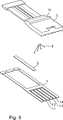
Anhand der
Der erfindungsgemäße Strömungssensor umfasst ein starres Trägerteil
Das Sensorelement zur Messung der Massenströmung wird in den Figuren mit dem Bezugszeichen
Das Sensorelement
Die eigentliche Massenstrom-Messung erfolgt im erfindungsgemäßen Strömungssensor über ein Heißfilmsensor-Prinzip, bei dem das Sensorelement
Der erfindungsgemäße Strömungssensor weist ferner eine Umkapselung
Aufgrund einer derartigen Ausbildung der Umkapselung
Senkrecht zur Längserstreckungsachse des Sensorelements
Grundsätzlich wäre es aus strömungstechnischer Sicht auch möglich, lediglich auf einer Seite benachbart zum Sensorelement die Umkapselung als Anströmkante auszubilden. Besonders vorteilhaft erweist sich die annähernd symmetrische Ausbildung des Strömungssensors in diesem Bereich jedoch auch deshalb, da damit ggf. resultierende mechanische Verspannungen minimierbar sind, die aufgrund von unterschiedlichen Material-Ausdehnungskoeffizienten auftreten können.In principle, it would also be possible, from a fluidic point of view, to form the encapsulation as leading edge only on one side adjacent to the sensor element. However, the approximately symmetrical design of the flow sensor in this area proves to be particularly advantageous also because any resulting mechanical stresses that can occur due to different material expansion coefficients can thereby be minimized.
Die derart über die Umkapselung
Neben der strömungstechnischen Funktionalität der Umkapselung
Die Umkapselung
An einem Längsende des Strömungssensors ist desweiteren ein Befestigungselement
Wie etwa aus den
Bei der Wahl der verschiedenen Materialien für den erfindungsgemäßen Strömungssensor ist grundsätzlich darauf zu achten, dass Materialien mit geringer Wärmeleitung bzw. Wärmeleitzahl λ und geringer Wärmekapazität c gewählt werden. Die entsprechenden Parameter aller verwendeten Materialien sind hierbei geeignet aufeinander abzustimmen. Desweiteren erweist sich als vorteilhaft, wenn sich die verwendeten Materialien hinsichtlich ihrer jeweiligen Wärmeausdehnungskoeffizienten CTE nicht zu stark unterscheiden.In the choice of the different materials for the flow sensor according to the invention is basically to make sure that materials with low heat conductivity or Wärmeleitzahl λ and low heat capacity c are selected. The corresponding parameters of all materials used here are suitably matched to each other. Furthermore, it proves to be advantageous if the materials used are not too different with respect to their respective thermal expansion coefficients CTE.
Die entsprechenden Parameter-Größenordnungen für die potentiellen Trägersubstratmaterialien Glas, Zirkondioxid, das Trägerteilmaterial Alloy
Zur Fertigung des erfindungsgemäßen Strömungssensors wird zunächst das Sensorelement
Neben den erläuterten Beispielen existieren im Rahmen der vorliegenden Erfindung selbstverständlich noch weitere Ausgestaltungsmöglichkeiten.In addition to the illustrated examples, there are, of course, further design possibilities within the scope of the present invention.
So wäre es etwa möglich, anstelle des im beschriebenen Beispiel vorgesehenen einzigen Trägersubstrats
ZITATE ENTHALTEN IN DER BESCHREIBUNG QUOTES INCLUDE IN THE DESCRIPTION
Diese Liste der vom Anmelder aufgeführten Dokumente wurde automatisiert erzeugt und ist ausschließlich zur besseren Information des Lesers aufgenommen. Die Liste ist nicht Bestandteil der deutschen Patent- bzw. Gebrauchsmusteranmeldung. Das DPMA übernimmt keinerlei Haftung für etwaige Fehler oder Auslassungen.This list of the documents listed by the applicant has been generated automatically and is included solely for the better information of the reader. The list is not part of the German patent or utility model application. The DPMA assumes no liability for any errors or omissions.
Zitierte PatentliteraturCited patent literature
- DE 102005016122 A1 [0004] DE 102005016122 A1 [0004]
Claims (14)
Priority Applications (6)
| Application Number | Priority Date | Filing Date | Title |
|---|---|---|---|
| DE102012009421A DE102012009421A1 (en) | 2012-05-11 | 2012-05-11 | flow sensor |
| EP13001841.9A EP2662670B1 (en) | 2012-05-11 | 2013-04-09 | Flow sensor |
| KR1020130043637A KR101930937B1 (en) | 2012-05-11 | 2013-04-19 | Flow sensor |
| US13/890,619 US9091579B2 (en) | 2012-05-11 | 2013-05-09 | Flow sensor |
| JP2013099176A JP6100081B2 (en) | 2012-05-11 | 2013-05-09 | Flow sensor |
| CN201310170786.7A CN103389134B (en) | 2012-05-11 | 2013-05-10 | Flow sensor |
Applications Claiming Priority (1)
| Application Number | Priority Date | Filing Date | Title |
|---|---|---|---|
| DE102012009421A DE102012009421A1 (en) | 2012-05-11 | 2012-05-11 | flow sensor |
Publications (1)
| Publication Number | Publication Date |
|---|---|
| DE102012009421A1 true DE102012009421A1 (en) | 2013-11-14 |
Family
ID=48092663
Family Applications (1)
| Application Number | Title | Priority Date | Filing Date |
|---|---|---|---|
| DE102012009421A Withdrawn DE102012009421A1 (en) | 2012-05-11 | 2012-05-11 | flow sensor |
Country Status (6)
| Country | Link |
|---|---|
| US (1) | US9091579B2 (en) |
| EP (1) | EP2662670B1 (en) |
| JP (1) | JP6100081B2 (en) |
| KR (1) | KR101930937B1 (en) |
| CN (1) | CN103389134B (en) |
| DE (1) | DE102012009421A1 (en) |
Families Citing this family (6)
| Publication number | Priority date | Publication date | Assignee | Title |
|---|---|---|---|---|
| KR102376169B1 (en) * | 2014-10-24 | 2022-03-18 | 와틀로 일렉트릭 매뉴팩츄어링 컴파니 | Rapid response sensor housing |
| DE102015219509A1 (en) * | 2015-10-08 | 2017-04-13 | Robert Bosch Gmbh | Sensor device for detecting at least one flow characteristic of a flowing fluid medium |
| DE102015118123A1 (en) | 2015-10-23 | 2017-04-27 | Endress+Hauser Flowtec Ag | Thermal flow meter and assembly with a tube and the thermal flow meter |
| DE102015225358B4 (en) | 2015-12-16 | 2020-04-02 | Continental Automotive Gmbh | Air mass meter |
| JP7437640B2 (en) | 2020-07-09 | 2024-02-26 | パナソニックIpマネジメント株式会社 | Delivery box lock/unlock system |
| JP7112001B2 (en) * | 2020-10-15 | 2022-08-03 | ダイキン工業株式会社 | Thermal velocity/flow sensor and air conditioner |
Citations (1)
| Publication number | Priority date | Publication date | Assignee | Title |
|---|---|---|---|---|
| DE102005016122A1 (en) | 2005-04-08 | 2006-10-12 | Robert Bosch Gmbh | Flow meter manufacture involves forming conductive strip for connecting with exposed contacts of electronic component and sensor chip after coating electronic component and sensor chip with molding compound |
Family Cites Families (17)
| Publication number | Priority date | Publication date | Assignee | Title |
|---|---|---|---|---|
| DE2751196C2 (en) * | 1977-11-16 | 1985-06-20 | Robert Bosch Gmbh, 7000 Stuttgart | Device for air volume measurement |
| JPS62123318A (en) * | 1985-08-13 | 1987-06-04 | Nippon Soken Inc | Direct heat type flow rate sensor |
| DE3838466C2 (en) * | 1988-01-16 | 1995-11-16 | Bosch Gmbh Robert | Air mass measuring device and method for producing an air mass measuring device |
| US4986122A (en) * | 1989-11-08 | 1991-01-22 | Hydro Data Inc. | Fluid velocity measurement instrument |
| JP2784286B2 (en) * | 1991-12-09 | 1998-08-06 | 三菱電機株式会社 | Method for manufacturing semiconductor sensor device |
| JP3331814B2 (en) * | 1995-05-18 | 2002-10-07 | 三菱電機株式会社 | Thermal flow detector |
| CN1155653A (en) * | 1995-05-19 | 1997-07-30 | 株式会社日立制作所 | Measuring element for mass air flow sensor and mass air flow sensor using measuring element |
| JP3416526B2 (en) * | 1998-05-21 | 2003-06-16 | 三菱電機株式会社 | Thermal flow sensor |
| JP3545637B2 (en) * | 1999-03-24 | 2004-07-21 | 三菱電機株式会社 | Thermal flow sensor |
| DE10036290A1 (en) * | 2000-07-26 | 2002-02-07 | Bosch Gmbh Robert | Device for determining at least one parameter of a flowing medium |
| JP3671393B2 (en) * | 2001-05-24 | 2005-07-13 | 三菱電機株式会社 | Thermal flow sensor |
| JP4830391B2 (en) * | 2005-07-29 | 2011-12-07 | 株式会社デンソー | Manufacturing method of sensor device and sensor device |
| JP2008058131A (en) * | 2006-08-31 | 2008-03-13 | Hitachi Ltd | Thermal type gas flowmeter |
| JP4882732B2 (en) | 2006-12-22 | 2012-02-22 | 株式会社デンソー | Semiconductor device |
| JP5183164B2 (en) * | 2007-11-19 | 2013-04-17 | 日立オートモティブシステムズ株式会社 | Flow measuring device |
| US7654157B2 (en) * | 2007-11-30 | 2010-02-02 | Honeywell International Inc. | Airflow sensor with pitot tube for pressure drop reduction |
| JP2011508193A (en) * | 2007-12-21 | 2011-03-10 | ノアグレン ゲゼルシャフト ミット ベシュレンクテル ハフツング | Thermal flow sensor with turbulence inducer |
-
2012
- 2012-05-11 DE DE102012009421A patent/DE102012009421A1/en not_active Withdrawn
-
2013
- 2013-04-09 EP EP13001841.9A patent/EP2662670B1/en active Active
- 2013-04-19 KR KR1020130043637A patent/KR101930937B1/en active IP Right Grant
- 2013-05-09 US US13/890,619 patent/US9091579B2/en active Active
- 2013-05-09 JP JP2013099176A patent/JP6100081B2/en not_active Expired - Fee Related
- 2013-05-10 CN CN201310170786.7A patent/CN103389134B/en active Active
Patent Citations (1)
| Publication number | Priority date | Publication date | Assignee | Title |
|---|---|---|---|---|
| DE102005016122A1 (en) | 2005-04-08 | 2006-10-12 | Robert Bosch Gmbh | Flow meter manufacture involves forming conductive strip for connecting with exposed contacts of electronic component and sensor chip after coating electronic component and sensor chip with molding compound |
Also Published As
| Publication number | Publication date |
|---|---|
| KR101930937B1 (en) | 2018-12-20 |
| KR20130126471A (en) | 2013-11-20 |
| EP2662670B1 (en) | 2016-11-09 |
| CN103389134A (en) | 2013-11-13 |
| EP2662670A1 (en) | 2013-11-13 |
| CN103389134B (en) | 2017-12-29 |
| JP2013238594A (en) | 2013-11-28 |
| JP6100081B2 (en) | 2017-03-22 |
| US9091579B2 (en) | 2015-07-28 |
| US20130298666A1 (en) | 2013-11-14 |
Similar Documents
| Publication | Publication Date | Title |
|---|---|---|
| EP2662670B1 (en) | Flow sensor | |
| DE102005025667B4 (en) | Method for producing a sensor arrangement with a cast-over signal output section | |
| DE112013001060B4 (en) | Thermal air volume measuring device | |
| EP2326923B1 (en) | Sensor arrangement for determining a parameter of a fluid medium | |
| DE19524634B4 (en) | Device for measuring the mass of a flowing medium | |
| DE60030333T2 (en) | DEVICE FOR MEASURING A PHYSICAL SIZE, METHOD FOR THE PRODUCTION THEREOF, AND A VEHICLE CONTROL SYSTEM WITH THE APPARATUS FOR MEASURING A PHYSICAL SIZE | |
| DE102013101731A1 (en) | Pressure Sensor System | |
| DE102014002991B4 (en) | Sensor housing for direct mounting | |
| DE112010001128T5 (en) | FLOW DETECTION ELEMENT AND ITS COUPLING | |
| DE102005027767A1 (en) | Integrated magnetic sensor component for e.g. measuring magnetic field intensity, has contact surfaces electrically connected with flat conductors by flip-chip-contacts and homogenization disk attached between semiconductor chip and magnet | |
| DE102006035000A1 (en) | Sensor device and method for its production | |
| DE19743409A1 (en) | System for measuring suction air mass flow in IC engine | |
| DE19744997A1 (en) | Device for measuring the mass of a flowing medium | |
| DE102005038598A1 (en) | Hot film air mass meter with flow separation element | |
| DE102005006158B4 (en) | Thermal air flow meter and method for its production | |
| DE112012006049T5 (en) | Flow sensor with manufacturing process | |
| DE112013002966T5 (en) | Thermal flow meter | |
| DE2809455A1 (en) | DEVICE FOR AIR VOLUME MEASUREMENT | |
| DE112013006062B4 (en) | Pressure sensor and process for its manufacture | |
| EP3942266A1 (en) | Sensor assembly comprising a temperature sensor element, and method for the production of said assembly | |
| DE112016004744T5 (en) | A sensor component for detecting a physical quantity and a device for measuring a physical quantity | |
| DE102007057903B4 (en) | Sensor module and method for producing the sensor module | |
| DE102011083174B4 (en) | Sensor for detecting a pressure and a temperature of a fluid medium | |
| DE102005054631A1 (en) | Sensor arrangement with a substrate and with a housing and method for producing a sensor arrangement | |
| DE102004045854A1 (en) | Semiconductor sensor, has hollow housing made up of plastic, and semiconductor sensor chip arranged on chip carrier in housing, where thermal characteristics of chip carrier correspond to semiconductor material of sensor chip |
Legal Events
| Date | Code | Title | Description |
|---|---|---|---|
| R119 | Application deemed withdrawn, or ip right lapsed, due to non-payment of renewal fee |