DE102011085599B3 - Apparatus and method for interferometric measurement of an object - Google Patents
Apparatus and method for interferometric measurement of an object Download PDFInfo
- Publication number
- DE102011085599B3 DE102011085599B3 DE102011085599A DE102011085599A DE102011085599B3 DE 102011085599 B3 DE102011085599 B3 DE 102011085599B3 DE 102011085599 A DE102011085599 A DE 102011085599A DE 102011085599 A DE102011085599 A DE 102011085599A DE 102011085599 B3 DE102011085599 B3 DE 102011085599B3
- Authority
- DE
- Germany
- Prior art keywords
- detector
- measuring
- reference beam
- designed
- measurement
- Prior art date
- Legal status (The legal status is an assumption and is not a legal conclusion. Google has not performed a legal analysis and makes no representation as to the accuracy of the status listed.)
- Expired - Fee Related
Links
Images


Classifications
-
- G—PHYSICS
- G01—MEASURING; TESTING
- G01B—MEASURING LENGTH, THICKNESS OR SIMILAR LINEAR DIMENSIONS; MEASURING ANGLES; MEASURING AREAS; MEASURING IRREGULARITIES OF SURFACES OR CONTOURS
- G01B9/00—Measuring instruments characterised by the use of optical techniques
- G01B9/02—Interferometers
- G01B9/02015—Interferometers characterised by the beam path configuration
- G01B9/02022—Interferometers characterised by the beam path configuration contacting one object by grazing incidence
-
- G—PHYSICS
- G01—MEASURING; TESTING
- G01B—MEASURING LENGTH, THICKNESS OR SIMILAR LINEAR DIMENSIONS; MEASURING ANGLES; MEASURING AREAS; MEASURING IRREGULARITIES OF SURFACES OR CONTOURS
- G01B9/00—Measuring instruments characterised by the use of optical techniques
- G01B9/02—Interferometers
- G01B9/02001—Interferometers characterised by controlling or generating intrinsic radiation properties
- G01B9/02002—Interferometers characterised by controlling or generating intrinsic radiation properties using two or more frequencies
-
- G—PHYSICS
- G01—MEASURING; TESTING
- G01B—MEASURING LENGTH, THICKNESS OR SIMILAR LINEAR DIMENSIONS; MEASURING ANGLES; MEASURING AREAS; MEASURING IRREGULARITIES OF SURFACES OR CONTOURS
- G01B9/00—Measuring instruments characterised by the use of optical techniques
- G01B9/02—Interferometers
- G01B9/02015—Interferometers characterised by the beam path configuration
- G01B9/02027—Two or more interferometric channels or interferometers
- G01B9/02028—Two or more reference or object arms in one interferometer
-
- G—PHYSICS
- G01—MEASURING; TESTING
- G01B—MEASURING LENGTH, THICKNESS OR SIMILAR LINEAR DIMENSIONS; MEASURING ANGLES; MEASURING AREAS; MEASURING IRREGULARITIES OF SURFACES OR CONTOURS
- G01B2290/00—Aspects of interferometers not specifically covered by any group under G01B9/02
- G01B2290/45—Multiple detectors for detecting interferometer signals
-
- G—PHYSICS
- G01—MEASURING; TESTING
- G01B—MEASURING LENGTH, THICKNESS OR SIMILAR LINEAR DIMENSIONS; MEASURING ANGLES; MEASURING AREAS; MEASURING IRREGULARITIES OF SURFACES OR CONTOURS
- G01B2290/00—Aspects of interferometers not specifically covered by any group under G01B9/02
- G01B2290/70—Using polarization in the interferometer
-
- G—PHYSICS
- G01—MEASURING; TESTING
- G01H—MEASUREMENT OF MECHANICAL VIBRATIONS OR ULTRASONIC, SONIC OR INFRASONIC WAVES
- G01H9/00—Measuring mechanical vibrations or ultrasonic, sonic or infrasonic waves by using radiation-sensitive means, e.g. optical means
Abstract
Die Erfindung betrifft eine Vorrichtung zur interferometrischen Vermessung eines Objekts, umfassend eine Strahlungsquelle zur Erzeugung eines Ausgangsstrahls, eine Strahlteilervorrichtung zur Aufteilung des Ausgangsstrahls in einen Mess- und einen ersten Referenzstrahl, eine optische Überlagerungsvorrichtung und einen ersten Detektor, wobei Überlagerungsvorrichtung und erster Detektor derart zusammenwirkend ausgestaltet sind, dass der von dem Objekt zumindest teilweise reflektierte Messstrahl und der erste Referenzstrahl auf mindestens einer Detektorfläche des ersten Detektors überlagert sind. Die Erfindung ist dadurch gekennzeichnet, dass die Strahlteilervorrichtung ausgebildet ist zur Aufteilung des Ausgangsstrahls in einen Messstrahl, einen ersten Referenzstrahl und mindestens einen zweiten Referenzstrahl, dass die Vorrichtung mindestens einen zweiten Detektor aufweist und Überlagerungsvorrichtung und zweiter Detektor derart zusammenwirkend ausgebildet sind, dass der von dem Objekt zumindest teilweise gestreute Messstrahl und der zweite Referenzstrahl auf mindestens einer Detektorfläche des zweiten Detektors überlagert sind. Die Erfindung betrifft weiterhin ein Verfahren zur interferometrischen Vermessung eines Objekts.The invention relates to a device for interferometric measurement of an object, comprising a radiation source for generating an output beam, a beam splitter device for dividing the output beam into a measuring and a first reference beam, an optical heterodyne device and a first detector, wherein the superposition device and the first detector cooperatively designed in such a way in that the measurement beam at least partially reflected by the object and the first reference beam are superimposed on at least one detector surface of the first detector. The invention is characterized in that the beam splitter device is designed for splitting the output beam into a measuring beam, a first reference beam and at least one second reference beam, that the device has at least one second detector and overlay device and second detector are designed to cooperate such that the Object at least partially scattered measuring beam and the second reference beam are superimposed on at least one detector surface of the second detector. The invention further relates to a method for the interferometric measurement of an object.

Description
Die Erfindung betrifft eine Vorrichtung zur interferometrischen Vermessung eines Objekts gemäß Oberbegriff des Anspruchs 1 sowie ein Verfahren zur interferometrischen Vermessung eines Objekts gemäß Oberbegriff des Anspruchs 12.The invention relates to a device for interferometric measurement of an object according to the preamble of
Vorrichtungen und Verfahren zur interferometrischen Vermessung eines Objekts sind in verschiedenen Ausgestaltungen bekannt: So ist beispielsweise ein typischer Aufbau als Laser-Doppler-Vibrometer bekannt, welche einen Laser als Strahlungsquelle zur Erzeugung eines Ausgangsstrahls umfasst, eine Strahlteilervorrichtung zur Aufteilung des Ausgangsstrahls in einen Mess- und einen Referenzstrahl, eine optische Überlagerungsvorrichtung und einen ersten Detektor.Devices and methods for interferometric measurement of an object are known in various embodiments: For example, a typical structure known as a laser Doppler vibrometer, which comprises a laser as a radiation source for generating an output beam, a beam splitter device for dividing the output beam into a measuring and a reference beam, an optical heterodyne device and a first detector.
Der Messstrahl wird auf einen Messpunkt auf dem Objekt geleitet und der zumindest teilweise reflektierte Messstrahl wird zusammen mit dem Referenzstrahl auf einer Detektorfläche des Detektors überlagert, so dass durch Auswertung des Interferenzsignals beispielsweise auf eine Bewegung der Objektoberfläche am Messpunkt in Richtung der optischen Achse des Messstrahls rückgeschlossen werden kann.The measuring beam is directed to a measuring point on the object and the at least partially reflected measuring beam is superimposed on a detector surface of the detector together with the reference beam, so that by evaluating the interference signal, for example, a movement of the object surface at the measuring point in the direction of the optical axis of the measuring beam can be.
Darüber hinaus sind Anordnungen bekannt, welche einen heterodynen Aufbau aufweisen, so dass sich durch eine Phasendemodulation im Messlicht auf die Auslenkungsrichtung der vermessenen Oberfläche schließen lässt. Ein heterodynes Vibrometer ist in
Um in zwei oder drei Dimensionen Schwingungsinformation zu erhalten, ist es bekannt, die Messstrahlen von drei Laser-Doppler-Vibrometern so zu führen, dass die Messstrahlen jeweils schräg zueinander in etwa auf einen Messpunkt auf dem Objekt auftreffen. Eine solche Vorrichtung ist in B. Cazzolauto, S. Wildy, J. Codrington, A. Kotousov, M. Schüssler, ”Scanning laser vibrometer for non-contact three-dimensional displacement and strain measurements”, Proc. of Acoustics 2008, 24–26 November, Geelong, Australia, (2008) beschrieben.In order to obtain oscillation information in two or three dimensions, it is known to guide the measurement beams of three laser Doppler vibrometers so that the measurement beams each impinge on one another approximately at a measuring point on the object. Such a device is described in B. Cazzolauto, S. Wildy, J. Codrington, A. Kotousov, M. Schüssler, "Scanning laser vibrometer for non-contact three-dimensional displacement and strain measurements", Proc. of Acoustics 2008, 24-26 November, Geelong, Australia, (2008).
Aus
Aus
Aus
Der vorliegenden Erfindung liegt die Aufgabe zugrunde, eine Vorrichtung zur interferometrischen Vermessung eines Objekts und ein Verfahren zur interferometrischen Vermessung eines Objekts zu schaffen, so dass die Ermittlung von zusätzlicher Information gegenüber den vorbekannnten Einstrahl-Laser-Doppler-Vibrometern möglich ist. Gleichzeitig soll ein robuster Aufbau und eine hohe Messgenauigkeit erzielt werden.The present invention has for its object to provide an apparatus for interferometric measurement of an object and a method for interferometric measurement of an object, so that the determination of additional information compared to the vorbekannnten single-beam laser Doppler vibrometers is possible. At the same time a robust construction and a high measuring accuracy should be achieved.
Gelöst ist diese Aufgabe durch eine Vorrichtung zur interferometrischen Vermessung eines Objekts gemäß Anspruch 1 sowie durch ein Verfahren zur interferometrischen Vermessung eines Objekts gemäß Anspruch 12. Vorzugsweise Ausgestaltungen der erfindungsgemäßen Vorrichtung finden sich in den Ansprüchen 2 bis 11; vorzugsweise Ausgestaltungen des erfindungsgemäßen Verfahrens finden sich in den Ansprüchen 13 bis 14. Hiermit wird der Wortlaut sämtlicher Ansprüche explizit per Referenz in die Beschreibung einbezogen.This object is achieved by a device for interferometric measurement of an object according to
Die erfindungsgemäße Vorrichtung zur interferometrischen Vermessung eines Objekts umfasst eine Strahlungsquelle zur Erzeugung eines Ausgangsstrahls, eine Strahlteilervorrichtung zur Aufteilung des Ausgangsstrahls in einen Mess- und einen ersten Referenzstrahl, eine optische Überlagerungsvorrichtung und einen ersten Detektor.The device according to the invention for the interferometric measurement of an object comprises a radiation source for generating an output beam, a beam splitter device for splitting the output beam into a measuring and a first reference beam, an optical heterodyne device and a first detector.
Die Überlagerungsvorrichtung und der erste Detektor sind derart zusammenwirkend ausgebildet, dass der von dem Objekt zumindest teilweise reflektierte Messstrahl und der erste Referenzstrahl auf mindestens einer Detektorfläche des ersten Detektors überlagert sind.The superposition device and the first detector are designed to cooperate such that the measurement beam at least partially reflected by the object and the first reference beam are superimposed on at least one detector surface of the first detector.
Hinsichtlich dieses Grundaufbaus entspricht die erfindungsgemäße Vorrichtung somit vorbekannten Interferometern, insbesondere weisen typische, aus dem Stand der Technik bekannte, Laser-Doppler-Vibrometer solch einen Aufbau auf.With regard to this basic construction, the device according to the invention thus corresponds to known interferometers, in particular typical laser Doppler vibrometers known from the prior art have such a structure.
Wesentlich ist, dass bei der erfindungsgemäßen Vorrichtung die Strahlteilervorrichtung ausgebildet ist zur Aufteilung des Ausgangsstrahls in einen Messstrahl, einen ersten Referenzstrahl und mindestens einen zweiten Referenzstrahl. Weiterhin weist die erfindungsgemäße Vorrichtung mindestens einen zweiten Detektor auf und die Überlagerungsvorrichtung und der zweite Detektor sind derart zusammenwirkend ausgebildet, dass der vom dem Objekt zumindest teilweise gestreute Messstrahl und der zweite Referenzstrahl auf mindestens einer Detektorfläche des zweiten Detektors überlagert sind.It is essential that in the apparatus according to the invention, the beam splitter device is designed for dividing the output beam into a measuring beam, a first reference beam and at least a second reference beam. Furthermore, the device according to the invention has at least one second detector and the superposition device and the second detector are such formed cooperatively, that the at least partially scattered by the object measuring beam and the second reference beam are superimposed on at least one detector surface of the second detector.
Die erfindungsgemäße Vorrichtung weist somit mindestens zwei Detektoren auf, auf denen jeweils Strahlen zur interferometrischen Auswertung überlagert werden. Im Gegensatz zu vorbekannten Vorrichtungen weist die erfindungsgemäße Vorrichtung jedoch lediglich einen Messstrahl auf, der einerseits hinsichtlich des zumindest teilweise reflektierten Messstrahls durch den ersten Detektor und andererseits hinsichtlich des zumindest teilweise von dem Objekt gestreuten Messstrahls durch den zweiten Detektor ausgewertet wird.The device according to the invention thus has at least two detectors, on each of which beams for interferometric evaluation are superimposed. In contrast to prior art devices, however, the device according to the invention has only one measuring beam, which is evaluated on the one hand with respect to the at least partially reflected measuring beam by the first detector and on the other hand with respect to the at least partially scattered by the object measuring beam by the second detector.
Die erfindungsgemäße Vorrichtung weist somit einen grundsätzlich verschiedenen Aufbau auf, da vorbekannte Vorrichtungen für jeden Detektor jeweils einen eigenen Messstrahl aufweisen.The device according to the invention therefore has a fundamentally different structure, since previously known devices each have their own measuring beam for each detector.
Die Erfindung ist insbesondere auf folgende Erkenntnis des Anmelders begründet:
Bei vorbekannten Vorrichtungen, bei denen mehrere Laser-Doppler-Vibrometer kombiniert werden, so dass beispielsweise bei Verwendung von drei Vibrometern drei Messstrahlen auf dem Objekt auftreffen, sollten optimalerweise die Foki der Messstrahlen exakt übereinander liegen, da sonst ein Messfehler bei Drehungen des Objekts um das Messpunktzentrum entsteht.The invention is based in particular on the following finding of the applicant:
In prior art devices in which several laser Doppler vibrometers are combined so that, for example, when using three vibrometers, three measuring beams impinge on the object, optimally the foci of the measuring beams should be exactly above one another, otherwise a measurement error in rotations of the object around the Measuring point center is created.
Bei Überlagerung der Messstrahlen auf dem Objekt, d. h. exakter Übereinstimmung der Messpunkte der mehreren Vibrometern, wird aber auch von jedem einzelnen Sensor das Messlicht der anderen beiden Vibrometern empfangen, da Streulicht nicht nur vom Messlicht des betrachteten Kanals, sondern auch Messlicht von den anderen Kanälen eingesammelt und auf dem Detektor zur Interferenz gebracht wird (optisches Übersprechen). Da typischerweise die Frequenzen der verwendeten Laser innerhalb eines Frequenzabstandes, welcher durch die Summe aus einer Demodulationsbandbreite und einer heterodynen Frequenzverschiebung definiert ist, zusammenfallen, ergibt sich ein erheblicher störender Effekt, der bis zu einem totalen Ausfall der Messfähigkeit der Sensoren führen kann.When superimposing the measuring beams on the object, d. H. exact match of the measuring points of the several vibrometers, but will also receive from each sensor, the measuring light of the other two vibrometers, since scattered light is collected not only by the measuring light of the channel considered, but also measuring light from the other channels and brought to the detector to interference ( optical crosstalk). Since typically the frequencies of the lasers used coincide within a frequency spacing which is defined by the sum of a demodulation bandwidth and a heterodyne frequency shift, a considerable disturbing effect results, which can lead to a total failure of the measuring capability of the sensors.
Umgeht man dieses Problem, indem die Messpunkte geringfügig örtlich nebeneinander liegen, so wird der vorgenannte Störeffekt verringert, jedoch nicht vollständig beseitigt.If one circumvents this problem by the measurement points are slightly local next to each other, the aforementioned disturbing effect is reduced, but not completely eliminated.
Die vorbekannten Verfahren unter Verwendung mehrerer Vibrometer mit jeweils einem Messstrahl weisen grundsätzlich das Problem des optischen Übersprechens der Detektoren aufgrund eingekoppelten Messlichts der Messstrahlen der anderen Vibrometer auf.The previously known methods using a plurality of vibrometers, each with one measuring beam, basically have the problem of optical crosstalk of the detectors due to the coupled measuring light of the measuring beams of the other vibrometers.
Im Stand der Technik besteht somit meist die Notwendigkeit, dass die Messpunkte der mehreren verwendeten Vibrometer auf dem Objekt örtlich nebeneinander liegen müssen, um ein optisches Übersprechen zumindest zu verringern. Hierdurch ist jedoch eine Grenze hinsichtlich des Messpunktdurchmessers gegeben, so dass typischerweise ein Messpunktdurchmesser von 35 μm nicht unterschritten werden kann. Es ist jedoch wünschenswert, mehrdimensionale Schwingungsinformation für Messpunktdurchmesser kleiner 35 μm, insbesondere kleiner 15 μm, weiter bevorzugt kleiner 5 μm zu erzielen.In the prior art, therefore, there is usually a need for the measuring points of the plurality of vibrometers used to be locally adjacent to one another on the object in order to at least reduce optical crosstalk. As a result, however, there is a limit to the measuring point diameter, so that typically a measuring point diameter of 35 μm can not be undershot. However, it is desirable to achieve multi-dimensional vibration information for measuring point diameter less than 35 microns, especially less than 15 microns, more preferably less than 5 microns.
Bei der Lösung nach Stand der Technik misst man koaxial mit jedem Vibrometerkanal. Bei einem schrägen Auftreffen des Messstrahls liegt der Hauptteil der Leistung der Streulichtkeule um den reflektierten Anteil des Strahls. Der Detektionswinkel zur Achse der Streulichtkeule beträgt daher das Doppelte des Einfallswinkels. Da man für einen kleinen Fokusdurchmesser eine hohe numerische Apertur (NA) benötigt, bedingt die gewünschte Größe des Messpunkts jedes einzelnen Strahls einen Öffnungswingel des Messstrahls. Dieser Zusammenhang ist bei einer gleichmäßigen Ausleuchtung der Apertur des Mikroskopobjektivs (Austrittspupille) durch den Zusammenhang
Da sich die Öffnungswinkel nicht überschneiden können, resultiert hieraus ein minimal möglicher Winkel zwischen den Strahlen. Untersuchungen des Anwenders haben gezeigt, dass es bei der Lösung des Stands der Technik die Empfindlichkeit eines schräg auftreffenden Vibrometerstrahls nicht mehr ausreichend für die meisten Oberflächen ist, wenn ein senkrecht auftreffender Vibrometerstrahl eingerichtet wird, da dann zwangsläufig der Einfallswinkel des schräg auftreffenden Vibrometers zu groß wird. Man muss daher bei beiden Vibrometern einen kleineren schrägen Winkel realisieren, damit der Einfallswinkel bei einem Vibrometer nicht zu groß wird.Since the opening angles can not overlap, this results in a minimum possible angle between the beams. User studies have shown that, in the prior art approach, the sensitivity of an obliquely incident beam of vibrometer is no longer sufficient for most surfaces when establishing a vertically impinging beam of vibrometer, since then the angle of incidence of the slanting vibrometer inevitably becomes too large , It is therefore necessary to realize a smaller oblique angle in both vibrometers so that the angle of incidence in a vibrometer does not become too large.
Es ist daher in der Regel nicht möglich, bei Verwendung von mehreren Vibrometern einen der Messstrahlen senkrecht auf die Oberfläche der Probe zu richten. Dies wäre messtechnisch jedoch wünschenswert weil dann ein Kanal direkt die Bewegung in z-Richtung misst (Sollausrichtung des Messkopfes, die senkrecht zur vorgesehenen Lage der Messoberfläche ist), ist aufgrund der vorgenannten Streulichtproblematik bei den aus dem Stand der Technik bekannten Vorrichtungen jedoch nicht realisierbar bzw. führt durch zu wenig Licht zu einem zu hohen Rauschpegel bei der Signalauswertung bei den schräg messenden Detektoren.It is therefore usually not possible to direct one of the measuring beams perpendicular to the surface of the sample when using several vibrometers. However, this would be metrologically desirable because then a channel directly measures the movement in the z-direction (target orientation of the measuring head, which is perpendicular to the intended position of the measuring surface), due to the aforementioned problem of stray light in the from the prior However, technology known devices can not be realized or leads to too high a noise level in the signal evaluation in the obliquely measuring detectors due to insufficient light.
Bei typischen aus dem Stand der Technik bekannten Aufbauten muss für jeden Messstrahl ein eigenes Objektiv verwendet werden, so dass kein Raum für ein weiteres Objektiv für eine Kamera zur Aufnahme eines ortsaufgelösten Messbildes vorliegt. Typischerweise muss daher bei den aus dem Stand der Technik bekannten Vorrichtungen eine Kamera mit Hilfe eines dichroitischen Strahlteilers über ein Objektiv eines der verwendeten Vibrometer eingekoppelt werden, um den Messpunkt für Justagezwecke dem Benutzer anzeigen zu können. Da das Objektiv aus den vorgenannten Gründen bei den vorbekannten Vorrichtungen einen schrägen Einfallswinkel zur Oberfläche des Objekts aufweist, ist auch das Bild der Kamera verzerrt und insbesondere nicht gleichmäßig (hinsichtlich verschiedener Ortspositionen) scharf. Hierdurch ist es insbesondere schwierig, eine scannende Messung unter Verwendung eines x-y-Tisches, welcher das Objekt verschiebt, durchzuführen.In typical constructions known from the prior art, a separate objective must be used for each measuring beam so that there is no room for a further objective for a camera for recording a spatially resolved measuring image. Typically, therefore, in the devices known from the prior art, a camera must be coupled by means of a dichroic beam splitter via a lens of one of the vibrometers used in order to display the measuring point for adjustment purposes the user. Since the lens for the aforementioned reasons in the prior art devices has an oblique angle of incidence to the surface of the object, and the image of the camera is distorted and in particular not uniform (with respect to different spatial positions) sharp. This makes it particularly difficult to perform a scanning measurement using an x-y table which displaces the object.
Die erfindungsgemäße Vorrichtung und das nachfolgend erfindungsgemäße Verfahren vermeiden all die vorgenannten Nachteile. Da lediglich ein Messstrahl ausgehend von der Vorrichtung auf die zu vermessende Oberfläche des Objekts gerichtet wird und einerseits ein reflektierter Anteil des Messstrahls und andererseits mindestens ein gestreuter Anteil des Messstrahls mit jeweils einem Detektor ausgewertet wird, kann somit Schwingungsinformation in mehreren Dimensionen ermittelt werden ohne dass – wie bei den vorbekannten Vorrichtungen – mehrere Messstrahlen auf das Objekt gerichtet werden müssen.The device according to the invention and the method according to the invention avoid all the aforementioned disadvantages. Since only one measuring beam is directed from the device to the surface to be measured of the object and on the one hand a reflected portion of the measuring beam and on the other hand evaluated at least one scattered portion of the measuring beam, each with a detector, thus vibration information can be determined in several dimensions without - As with the previously known devices - several measuring beams must be directed to the object.
Hierdurch sind die vorgenannten Probleme durch optisches Übersprechen und entsprechende Schwierigkeiten bei der Signalauswertung, Platzprobleme hinsichtlich verwendeter Objekte zur Fokussierung des Messstrahls auf das Objekt sowie Begrenzungen hinsichtlich möglicher Einfallswinkel des Messstrahls auf das Objekt beseitigt.As a result, the aforementioned problems are eliminated by optical crosstalk and corresponding difficulties in the signal evaluation, space problems with respect to the objects used to focus the measuring beam on the object and limitations on possible angles of incidence of the measuring beam on the object.
Die vorbeschriebene Aufgabe ist ebenfalls gelöst durch das erfindungsgemäße Verfahren zur interferometrischen Vermessung eines Objekts, welches folgende Verfahrensschritte umfasst:
In einem Verfahrensschritt A wird ein Ausgangsstrahl mittels einer Lichtquelle erzeugt, in einem Verfahrensschritt B erfolgt ein Aufteilen des Ausgangsstrahls mittels einer Strahlteilervorrichtung in einen Mess- und einem ersten Referenzstrahl. In einem Verfahrensschritt C erfolgt ein Überlagern des ersten Referenzstrahls und des in Anspruch 12 und des zumindest teilweise von dem Objekt reflektierten Messstrahls auf mindestens einer Detektorfläche eines ersten Detektors.The above-described object is likewise achieved by the method according to the invention for the interferometric measurement of an object, which comprises the following method steps:
In a method step A, an output beam is generated by means of a light source, in a method step B, the output beam is divided by means of a beam splitter device into a measuring and a first reference beam. In a method step C, the first reference beam and the measurement beam reflected in at least one of the object and at least partially reflected by the object are superimposed on at least one detector surface of a first detector.
Wesentlich ist, dass in Verfahrensschritt B der Ausgangsstrahl zusätzlich in mindestens einen zweiten Referenzstrahl aufgeteilt wird und der zweite Referenzstrahl mit dem zumindest teilweise von dem Objekt mit einem gegenüber dem reflektierten Messstrahl zur Überlagerung auf dem ersten Detektor hier mit einem in einen anderen Winkelbereich an dem Objekt gestreuten Messstrahl auf mindestens einer Detektorfläche eines zweiten Detektors überlagert wird. Dieses in den anderen Winkelbereich gestreute Licht, welches auf der anderen Detektorfläche mit einem zweites Referenzstrahl überlagert wird, wird im folgenden Empfangslicht und der zugehörige optische Strahlenweg Empfangsstrahl genannt.It is essential that in method step B, the output beam is additionally divided into at least one second reference beam and the second reference beam with the at least partially from the object with a relation to the reflected measuring beam for superposition on the first detector here with a in another angular range of the object scattered measuring beam is superimposed on at least one detector surface of a second detector. This light scattered in the other angular range, which is superimposed on the other detector surface with a second reference beam, is called receive beam in the following received light and the associated optical beam path.
Das erfindungsgemäße Verfahren weist die vorgenannten Vorteile der erfindungsgemäßen Vorrichtung auf.The inventive method has the aforementioned advantages of the device according to the invention.
Die erfindungsgemäße Vorrichtung ist vorzugsweise ausgebildet zur Durchführung des erfindungsgemäßen Verfahrens bzw. einer vorzugsweise Ausführungsform hiervon. Das erfindungsgemäße Verfahren ist vorzugsweise zur Durchführung mittels einer erfindungsgemäßen Vorrichtung bzw. einer vorzugsweisen Ausführungsform hiervon ausgebildet.The device according to the invention is preferably designed for carrying out the method according to the invention or a preferred embodiment thereof. The method according to the invention is preferably designed for implementation by means of a device according to the invention or a preferred embodiment thereof.
Vorzugsweise werden mittels des ersten Detektors im Wesentlichen von dem Objekt reflektierte Anteile des Messstrahls, d. h. koaxial zur optischen Achse des Messstrahls reflektierte Lichtstrahlen bzw. Lichtstrahlenbündel gemessen. Demgegenüber werden mittels des zweiten Detektors gestreute Anteile des Messstrahls (der Empfangsstrahl), d. h. vorzugsweise Anteile, welche schräg, also nicht parallel, zur optischen Achse des Messstrahls stehen bzw. entsprechende Strahlenbündel gemessen.Preferably, by means of the first detector, portions of the measuring beam which are substantially reflected by the object, ie. H. Coaxial to the optical axis of the measuring beam reflected light beams or light beams measured. In contrast, by means of the second detector scattered portions of the measuring beam (the receiving beam), d. H. Preferably, portions which are oblique, that is not parallel, to the optical axis of the measuring beam or measured corresponding beam.
Die Erfindung ist weiterhin in der Erkenntnis des Anmelders begründet, dass auch das gestreute Licht, welches unter einem schrägen Winkel beispielsweise von einem Objektiv eingesammelt und auf den zweiten Detektor abgebildet wird, bei einer bewegten Oberfläche des Objekts Doppler-Frequenz verschoben ist. Allerdings kann die bei den vorbekannten Vorrichtungen verwendete Methode zur Auswertung der Messsignale des Detektors hier nicht unverändert angewandt werden. Hingegen kann eine aus der Literatur bekannte, jedoch bisher nicht im Rahmen der erfindungsgemäßen Vorrichtung oder des erfindungsgemäßen Verfahrens verwendete Formel für den richtungsabhängigen Doppler-Effekt verwendet werden, um die Phasen- und/oder Frequenzverschiebung korrekt gemäß nachfolgender Formel 1 zu beschreiben:
Die geometrischen Größen können aus der schematischen Darstellung gemäß
Sofern der Messstrahl senkrecht im betrachteten Koordinatensystem einfällt, vereinfacht sich Formel 1 zu Formel 2:
Vorzugsweise trifft aus den zuvor genannten Gründender Messstrahl in etwa senkrecht auf die zu vermessende Fläche des Messobjekts auf.Preferably, the measurement beam impinges on the surface of the measurement object that is approximately perpendicular to the surface to be measured for the above-mentioned reasons.
Wie vorhergehend beschrieben, umfasst die erfindungsgemäße Vorrichtung vorzugsweise ein erstes Objektiv, welches im Strahlengang des Messstrahls und des ersten Referenzstrahls zwischen Objekt und erstem Detektor angeordnet ist.As described above, the device according to the invention preferably comprises a first objective, which is arranged in the beam path of the measurement beam and the first reference beam between the object and the first detector.
Hierdurch kann insbesondere der Messstrahl auf einen Messpunkt auf dem Objekt fokussiert werden. Vorzugsweise weist das Objektiv eine numerische Apertur größer 0,05, bevorzugt größer 0,1, insbesondere bevorzugt größer gleich 0,2 auf. Hierdurch ergibt sich der Vorteil, dass dann gemäß Formel 0 sich ein kleiner Messfokus ergibt, der insbesondere bei einer vorzugsweise verwendeten grünen Wellenlänge deutlich unter 5 μm beträgt auch wenn die Apertur des Objektivs mit einem Gaußförmigen Strahl ausgeleuchtet wird. Da kein weiterer Laserstrahl auf die Messoberfläche trifft entspricht der Fokusdurchmesser des Messtrahls der Messpunktgröße des gesamten Systems. Durch den Umstand, dass nur ein Laserstrahl auf das Objekt trifft, wird ein extrem kleiner Messpunkt erreicht und optisches Übersprechen kann nicht auftreten. Diese wesentliche Erkenntnis hat zu dem Konzept dieser Erfindung geführt.In this way, in particular, the measuring beam can be focused on a measuring point on the object. Preferably, the objective has a numerical aperture greater than 0.05, preferably greater than 0.1, particularly preferably greater than or equal to 0.2. This results in the advantage that according to formula 0 results in a small measurement focus, which is significantly less than 5 microns especially at a preferably used green wavelength, even if the aperture of the lens is illuminated with a Gaussian beam. Since no further laser beam strikes the measurement surface, the focus diameter of the measurement beam corresponds to the measurement point size of the entire system. Due to the fact that only one laser beam strikes the object, an extremely small measuring point is reached and optical crosstalk can not occur. This essential insight has led to the concept of this invention.
Weiterhin ist es vorteilhaft, dass das erste Objektiv ebenso im Strahlengang des Empfangsstrahls zwischen Objekt und zweitem Detektor angeordnet ist. Auf diese Weise ist somit lediglich ein Objektiv notwendig, um einerseits den reflektierten Messstrahl auf den ersten Detektor und andererseits den gestreuten Messstrahl (Empfangsstrahl) auf den zweiten Detektor abzubilden.Furthermore, it is advantageous that the first objective is likewise arranged in the beam path of the receiving beam between the object and the second detector. In this way, therefore, only one objective is necessary in order, on the one hand, to image the reflected measuring beam onto the first detector and, on the other hand, the scattered measuring beam (receiving beam) onto the second detector.
In einer weiteren vorzugsweisen Ausführungsform umfasst die Vorrichtung ein zweites Objektiv, welches im Strahlengang des Empfangsstrahls zwischen Objekt und zweitem Detektor angeordnet ist. Hierdurch kann somit durch das zweite Objektiv gezielt die optische Abbildung des gestreuten Messstrahls auf den zweiten Detektor gewählt werden. Insbesondere ist es vorteilhaft, dass die numerische Apertur des zweiten Objektivs kleiner 0,15, bevorzugt kleiner 0,1, weiter bevorzugt kleiner 0,06 ist. Die numerische Apertur kann kleiner gewählt werden, da die Messpunktgröße nicht durch die numerische Apertur des Empfangsstrahl beeinflusst wird. Hierdurch ergeben sich die Vorteile, dass ein kleinerer Detektionswinkel gewählt werden kann, der mindestens der Summe aus halben Öffnungswinkel des Messstrahls und dem halben Öffnungswinkel des Empfangsstrahl betragen muss. Des Weiteren führt dass zu einem größeren Überlappungsbereich in z-Richtung, was einem größeren Tiefenmessbereich entspricht.In a further preferred embodiment, the device comprises a second objective, which is arranged in the beam path of the receiving beam between the object and the second detector. As a result, the optical imaging of the scattered measuring beam onto the second detector can thus be selectively selected by the second objective. In particular, it is advantageous that the numerical aperture of the second objective is less than 0.15, preferably less than 0.1, more preferably less than 0.06. The numerical aperture can be made smaller because the measurement point size is not affected by the numerical aperture of the receive beam. This results in the advantages that a smaller detection angle can be selected, which must be at least the sum of half the opening angle of the measuring beam and half the opening angle of the receiving beam. Furthermore, this leads to a larger overlap area in the z direction, which corresponds to a larger depth measurement range.
In einer weiteren vorzugsweisen Ausführungsform ist die erfindungsgemäße Vorrichtung zur heterodynen Messung mittels des ersten Detektors ausgebildet, indem eine Vorrichtung zur Frequenzverschiebung zwischen Messstrahl und erstem Referenzstrahl vorgesehen ist, die sich vorzugsweise mit einem optischen Frequenzschieber, wie z. B. einer Bragg-Zelle erreichen lässt. Hierdurch lässt sich somit in an sich bekannter Weise auch die Bewegungsrichtung der vermessenden Oberfläche des Objekts ermitteln. Insbesondere ist es vorteilhaft, dass bei allen Referenzstrahlen jeweils zwischen Messstrahl und Referenzstrahl eine Frequenzverschiebevorrichtung vorgesehen ist, so dass der heterodyne Aufbau somit hinsichtlich aller Referenzstrahlen gegeben ist. Ein besonders einfacher Aufbau ergibt sich in der vorzugsweisen Ausgestaltung, in welcher lediglich der Messstrahl frequenzmoduliert wird, so dass der Messstrahl gegenüber allen Referenzstrahlen hinsichtlich der Frequenz verschoben ist und somit ein komplett heterodyner Aufbau hinsichtlich aller Detektoren vorliegt.In a further preferred embodiment, the device according to the invention for heterodyne measurement by means of the first detector is formed by a device for frequency shift between the measuring beam and the first reference beam is provided, preferably with an optical frequency shifter, such as. B. can reach a Bragg cell. As a result, the direction of movement of the measuring surface of the object can thus be determined in a manner known per se. In particular, it is advantageous that a frequency shifting device is provided in each case between the measuring beam and the reference beam in all reference beams, so that the heterodyne structure is thus given with regard to all reference beams. A particularly simple construction results in the preferred embodiment, in which only the measuring beam is frequency-modulated, so that the measuring beam is shifted with respect to the frequency with respect to all reference beams and thus there is a completely heterodyne structure with respect to all detectors.
In einer weiteren vorzugsweisen Ausführungsform ist die Vorrichtung hinsichtlich der Strahlengänge von Messstrahl und erstem Referenzstrahl als konfokales Mikroskop ausgebildet. Hierdurch ergibt sich der Vorteil, dass nicht fokale Strahlen nicht auf den Detektor abgebildet werden. Ein typischer konfokaler Aufbau kann durch Vorsehen einer optischen Lochblende im Strahlengang von Messstrahl und erstem Referenzstrahl realisiert werden. Vorzugsweise wird der konfokale Aufbau durch Ausbildung des Detektors als optische Lochblende erzielt.In a further preferred embodiment, the device is designed as a confocal microscope with respect to the beam paths of the measuring beam and the first reference beam. This has the advantage that non-focal rays are not imaged on the detector. A typical confocal design can be realized by providing an optical pinhole in the beam path of the measuring beam and the first reference beam. Preferably, the confocal structure is achieved by forming the detector as an optical pinhole.
In einer weiteren vorzugsweisen Ausführungsform ist die Strahlteilervorrichtung ausgebildet zur Aufteilung des Ausgangsstrahls in einen Messstrahl, einen ersten Referenzstrahl, einen zweiten Referenzstrahl und mindestens einen dritten Referenzstrahl. Weiterhin umfasst die Vorrichtung mindestens einen dritten Detektor und Überlagerungsvorrichtung und dritter Detektor sind derart zusammenwirkend ausgebildet, dass der von dem Objekt zumindest teilweise gestreute Messstrahl und der dritte Referenzstrahl auf mindestens einer Detektorfläche des dritten Detektors überlagert sind. Hierdurch ist eine Vermessung einer Schwingung oder Auslenkung der Oberfläche des Objekts in drei Dimensionen möglich.In a further preferred embodiment, the beam splitter device is designed to divide the output beam into a measuring beam, a first reference beam, a second reference beam and at least one third reference beam. Furthermore, the device comprises at least a third detector and overlay device and third detector are formed cooperatively, that of the object at least partially scattered measuring beam and the third reference beam are superimposed on at least one detector surface of the third detector. As a result, a measurement of a vibration or deflection of the surface of the object in three dimensions is possible.
Insbesondere ist es vorteilhaft, dass die Vorrichtung derart ausgebildet ist, dass eine erste Ebene, welche durch den Messstrahl und den Empfangsstrahl definiert ist, mit einer zweiten Ebene, welche durch den Messstrahl und den dritten Referenzstrahl gebildet wird, einen Winkel größer 45°, bevorzugt größer 85° einschließt. Hierdurch ist es gewährleistet, dass eine hinreichend genaue Auftrennung der Bewegungsinformation in drei Dimensionen möglich ist.In particular, it is advantageous that the device is designed such that a first plane, which is defined by the measuring beam and the receiving beam, with a second plane, which is formed by the measuring beam and the third reference beam, an angle greater than 45 °, preferred greater than 85 °. This ensures that a sufficiently accurate separation of the movement information in three dimensions is possible.
Vorzugsweise beträgt der Winkel zwischen Messstrahl und zumindest erstem Empfangsstrahl weniger als 40°, bevorzugt weniger als 30°. Insbesondere ist es vorteilhaft, dass bei allen Empfangsstrahlen jeweils der Winkel zwischen Messstrahl und Empfangsstrahl kleiner 40°, bevorzugt kleiner 30° ist. Hierdurch ist ein hohes Signal-Rauschverhältnis, bei den Empfangsstrahlen und ein großer Tiefenmessbereich gewährleistet.Preferably, the angle between the measuring beam and at least the first receiving beam is less than 40 °, preferably less than 30 °. In particular, it is advantageous that the angle between the measuring beam and the receiving beam is less than 40 °, preferably less than 30 °, for all received beams. This ensures a high signal-to-noise ratio, with the receive beams and a large depth measurement range.
Vorzugsweise ist die Strahlungsquelle als longitudinal einmodiger Laser ausgebildet. Hierdurch ergibt sich der Vorteil, dass es zu keinen Störeffekten durch optische Mischeffekte zwischen den Moden kommt. Insbesondere ist es vorteilhaft, die Strahlungsquelle zusätzlich als transversal einmodigenen Laser auszubilden, so dass sich weiterhin der Vorteil ergibt, dass sich der Messlaserstrahl optimal fokussieren lässt und ein minimaler Messpunktdurchmesser erreicht wird. Ein Laser mit einem M2-Faktor kleiner 1,5 hat sich als ausreichend für eine gute Fokussierung erwiesen.Preferably, the radiation source is designed as a longitudinally single-mode laser. This results in the advantage that there are no disturbing effects due to optical mixing effects between the modes. In particular, it is advantageous to additionally design the radiation source as a transversally single-mode laser, so that the further advantage is that the measuring laser beam can be optimally focused and a minimum measuring point diameter is achieved. A laser with an M 2 factor smaller than 1.5 has proven to be sufficient for a good focus.
Untersuchungen des Anmelders haben gezeigt, dass insbesondere die Ausbildung der Strahlungsquelle als Laser mit einer Wellenlänge im sichtbaren Bereich, vorzugsweise als DPSS-Laser mit einer Wellenlänge von 532 nm vorteilhaft ist.Applicant's investigations have shown that, in particular, the formation of the radiation source is advantageous as a laser with a wavelength in the visible range, preferably as a DPSS laser with a wavelength of 532 nm.
Um einen kleinen Messfleck zu erzielen ist es vorteilhaft, wenn alle Detektoren lediglich Licht des reflektierten oder gestreuten Messstrahls einer Messfläche auf dem Objekt mit einem Durchmesser kleiner 35 μm, insbesondere kleiner 15 μm, weiter bevorzugt kleiner 5 μm auswerten. Insbesondere sind die optischen Komponenten und hierbei beispielsweise ein oder mehrere Objektive der Vorrichtung vorzugsweise derart ausgebildet, dass ein Messbereich auf dem Objekt mit einem Durchmesser kleiner 35 μm, insbesondere kleiner 15 μm, weiter bevorzugt kleiner 5 μm auf die Messfläche der Detektoren abgebildet wird.In order to achieve a small measuring spot, it is advantageous if all detectors only evaluate light of the reflected or scattered measuring beam of a measuring surface on the object with a diameter of less than 35 μm, in particular less than 15 μm, more preferably less than 5 μm. In particular, the optical components and in this case, for example, one or more objectives of the device are preferably designed such that a measuring range on the object with a diameter of less than 35 μm, in particular less than 15 μm, more preferably less than 5 μm, is imaged onto the measuring surface of the detectors.
Das erfindungsgemäße Verfahren ist vorzugsweise derart ausgebildet, dass die Messsignale des ersten und des zweiten Detektors jeweils phasendemoduliert werden, so dass eine mehrdimensionale Auswertung der Auslenkung der Oberfläche des Objekts durchgeführt werden kann.The method according to the invention is preferably designed such that the measurement signals of the first and the second detector are in each case phase-demodulated, so that a multi-dimensional evaluation of the deflection of the surface of the object can be carried out.
In einer weiteren vorzugsweisen Ausführungsform des erfindungsgemäßen Verfahrens werden die Messsignale des ersten Detektors phasendemoduliert, um eine Auslenkung der Oberfläche des Objekts durchzuführen und die Messsignale des zweiten Detektors werden amplitudendemoduliert, um eine Auswertung der Intensität des gestreuten Messstrahls durchzuführen. Hiermit kann somit in einfacher Weise sowohl die Auslenkung in Richtung der optischen Achse des Messstrahls sowie die Intensität des Streulichts mit bisher nicht erreichter Genauigkeit gemessen werden. Hierdurch ergibt sich eine Vielzahl neuer Anwendungsformen:
Insbesondere ist es möglich, Unebenheiten oder Einschlüsse von Fehlpartikeln auf einer im wesentlichen glatten Oberfläche zu detektieren, indem einmal durch Relativbewegung des Messstrahls zur Oberfläche die Oberflächenänderung (im übertragenen Sinne die „Auslenkung”) durch Phasendemodulation der Messsignale des ersten Detektors und darüber hinaus das durch die Fehlpartikel gestreute Licht mittels Amplitudendemodulation der Messsignale des zweiten Detektors ermittelt wird.In a further preferred embodiment of the method according to the invention, the measurement signals of the first detector are phase demodulated to perform a deflection of the surface of the object and the measurement signals of the second detector are amplitude demodulated to perform an evaluation of the intensity of the scattered measurement beam. In this way, the deflection in the direction of the optical axis of the measuring beam as well as the intensity of the scattered light can be measured with hitherto unachieved accuracy in a simple manner. This results in a variety of new applications:
In particular, it is possible to detect unevenness or inclusions of defective particles on a substantially smooth surface by once by relative movement of the measuring beam to the surface, the surface change (in a figurative sense, the "deflection") by phase demodulation of the measuring signals of the first detector and beyond that by the missing particles scattered light is determined by means of amplitude demodulation of the measuring signals of the second detector.
Vorzugsweise ist das erfindungsgemäße Verfahren daher derart ausgeführt, dass eine Oberflächentopografie des Objekts bestimmt wird, folgende Verfahrensschritte umfassend:
- – Bewegen des Objekts relativ zu dem Messstrahl, vorzugsweise im Wesentlichen senkrecht zur optischen Achse des Messstrahls und
- – Messen der Auslenkung mittels des ersten Detektors sowie Messen des Streulichts mittels des zweiten Detektors.
- Moving the object relative to the measuring beam, preferably substantially perpendicular to the optical axis of the measuring beam and
- - Measuring the deflection by means of the first detector and measuring the scattered light by means of the second detector.
Weitere Merkmale und vorzugsweisen Ausführungsformen werden im Folgenden anhand von den Figuren und Ausführungsbeispielen beschrieben. Dabei zeigt:Further features and preferred embodiments are described below with reference to the figures and exemplary embodiments. Showing:
Zum einfacheren Verständnis wird daher zunächst das erste Ausführungsbeispiel anhand der schematischen Darstellung gemäß
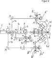
Bei dem ersten Ausführungsbeispiel ist eine Strahlungsquelle
In the first embodiment is a
Die Strahlteilervorrichtung umfasst hierfür mehrere Strahlteiler
Der Aufbau des ersten Fotodetektors entspricht somit dem an sich bekannten Aufbau einer so genannten „balanced detector” Anordnung.The structure of the first photodetector thus corresponds to the known structure of a so-called "balanced detector" arrangement.
Mittels einer Lochblende A im Strahlengang des Messstrahls und ersten Referenzstrahls ist ein konfokaler Aufbau realisiert.By means of a pinhole A in the beam path of the measuring beam and the first reference beam a confocal construction is realized.
Weiterhin ist im Strahlengang des Messstrahls
Der erste Messstrahl wird in an sich bekannter Weise über ein Teleskop T und Lambda Viertelplättchen QWP auf den Messpunkt A auf dem Objekt
Die Vorrichtung gemäß
In analoger Weise ist ein drittes Objektiv
Die Vorrichtung ist vorzugsweise derart angeordnet und ausgebildet, dass der Messstrahl
Der mittels des ersten Objektivs
Hierzu weist das erste Objektiv eine nummerische Apertur von etwa 0,2 auf. Die nummerischen Aperturen von zweitem und dritten Objektiv
Die drei Detektoren
Auf diese Weise ist es somit möglich, beispielsweise eine Bewegung des Messpunktes A auf der Oberfläche des Objekts
Zur Auswertung der dreidimensionalen Schwingungsinformation wird der richtungsabhängige Doppler-Effekt berücksichtigt, vorzugsweise gemäß Formel 1.To evaluate the three-dimensional vibration information, the direction-dependent Doppler effect is taken into account, preferably according to
Die Bedeutung der geometrischen Parameter aus Formel 1 sind in der schematischen Darstellung gemäß
Die als Laser ausgebildete Strahlungsquelle, deren Ausgangsstrahl in einen Messstrahl
The trained as a laser radiation source, the output beam in a
Unter einem Winkel β2 ist der zweite Detektor
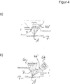
Wie bereits ausgeführt, zeigt
In
In Teilbild A ist ein Ausführungsbeispiel dargestellt, bei dem mittels lediglich eines Objektivs sowohl Messstrahl
In part A, an embodiment is shown, in which by means of only one lens both measuring
In Teilbild B ist hingegen ein Ausführungsbeispiel dargestellt, bei dem mittels eines ersten Objektivs
Claims (14)
Priority Applications (7)
| Application Number | Priority Date | Filing Date | Title |
|---|---|---|---|
| DE102011085599A DE102011085599B3 (en) | 2011-11-02 | 2011-11-02 | Apparatus and method for interferometric measurement of an object |
| EP12188513.1A EP2589924B1 (en) | 2011-11-02 | 2012-10-15 | Device and method for interferometric measuring of an object |
| SG2012080263A SG189672A1 (en) | 2011-11-02 | 2012-10-30 | Device and method for interferometric measuring of an object |
| JP2012242650A JP2013096997A (en) | 2011-11-02 | 2012-11-02 | Optical interference measuring instrument and optical interference measuring method for object |
| US13/667,309 US10018460B2 (en) | 2011-11-02 | 2012-11-02 | Interferometric measuring device with detectors set at different angular ranges |
| CN201210434215.5A CN103090786B (en) | 2011-11-02 | 2012-11-02 | Apparatus and method for measuring object with interferometry |
| JP2018090906A JP6631978B2 (en) | 2011-11-02 | 2018-05-09 | Optical interference measuring apparatus and optical interference measuring method for object |
Applications Claiming Priority (1)
| Application Number | Priority Date | Filing Date | Title |
|---|---|---|---|
| DE102011085599A DE102011085599B3 (en) | 2011-11-02 | 2011-11-02 | Apparatus and method for interferometric measurement of an object |
Publications (1)
| Publication Number | Publication Date |
|---|---|
| DE102011085599B3 true DE102011085599B3 (en) | 2012-12-13 |
Family
ID=47137545
Family Applications (1)
| Application Number | Title | Priority Date | Filing Date |
|---|---|---|---|
| DE102011085599A Expired - Fee Related DE102011085599B3 (en) | 2011-11-02 | 2011-11-02 | Apparatus and method for interferometric measurement of an object |
Country Status (6)
| Country | Link |
|---|---|
| US (1) | US10018460B2 (en) |
| EP (1) | EP2589924B1 (en) |
| JP (2) | JP2013096997A (en) |
| CN (1) | CN103090786B (en) |
| DE (1) | DE102011085599B3 (en) |
| SG (1) | SG189672A1 (en) |
Families Citing this family (6)
| Publication number | Priority date | Publication date | Assignee | Title |
|---|---|---|---|---|
| US9829373B1 (en) * | 2014-09-19 | 2017-11-28 | The United States Of America As Represented By The Secretary Of The Army | Apparatus and method for improving detection precision in laser vibrometric studies |
| DE102015003019A1 (en) * | 2015-03-06 | 2016-09-08 | Fraunhofer-Gesellschaft zur Förderung der angewandten Forschung e.V. | Method and device for the optical detection of movement in a biological sample with spatial extent |
| DE102018111921B4 (en) * | 2018-05-17 | 2023-11-23 | Technische Universität Clausthal | Contactless optical strain gauge sensor |
| CN108548489A (en) * | 2018-05-24 | 2018-09-18 | 郑州辰维科技股份有限公司 | A method of precision measure being carried out to solid surface antenna using optical markers |
| CN108548506A (en) * | 2018-05-24 | 2018-09-18 | 郑州辰维科技股份有限公司 | A method of the measurement of planeness being carried out to high precision plane using optical markers |
| CN111307268B (en) * | 2020-03-11 | 2021-01-01 | 北京理工大学 | Laser confocal/differential confocal vibration parameter measuring method |
Citations (4)
| Publication number | Priority date | Publication date | Assignee | Title |
|---|---|---|---|---|
| US5080491A (en) * | 1990-01-04 | 1992-01-14 | National Research Council Canada | Laser optical ultarasound detection using two interferometer systems |
| US5229832A (en) * | 1991-07-08 | 1993-07-20 | Industrial Quality, Inc. | Optical ultrasonic material characterization apparatus and method |
| DE10393244T5 (en) * | 2002-09-09 | 2005-09-01 | Zygo Corp., Middlefield | Interferometric method for ellipsometric, reflectometric and scattered-light analytical measurements, including the characterization of thin-film structures |
| DE102008017119A1 (en) * | 2008-04-02 | 2009-10-08 | Polytec Gmbh | Vibrometer and method for optical measurement of an object |
Family Cites Families (27)
| Publication number | Priority date | Publication date | Assignee | Title |
|---|---|---|---|---|
| GB1472894A (en) * | 1974-03-15 | 1977-05-11 | Nat Res Dev | Interferometric methods and apparatus for measuring distance to a surface |
| US5087121A (en) | 1987-12-01 | 1992-02-11 | Canon Kabushiki Kaisha | Depth/height measuring device |
| JPH0781836B2 (en) * | 1987-12-01 | 1995-09-06 | キヤノン株式会社 | Optical measuring device |
| JPH01282488A (en) * | 1988-05-10 | 1989-11-14 | Asahi Glass Co Ltd | Optical fiber sensor |
| JPH07297248A (en) * | 1994-04-20 | 1995-11-10 | Hitachi Ltd | Crystal defect measuring device and method of manufacturing semiconductor device |
| FR2750215B1 (en) * | 1996-06-25 | 1998-09-11 | Sextant Avionique | OPTICAL VELOCIMETRIC PROBE |
| US5883714A (en) * | 1996-10-07 | 1999-03-16 | Phase Metrics | Method and apparatus for detecting defects on a disk using interferometric analysis on reflected light |
| JPH10227617A (en) * | 1997-02-12 | 1998-08-25 | Nikon Corp | Mocroline width measuring method and apparatus |
| US6137585A (en) * | 1998-05-15 | 2000-10-24 | Laser Diagnostic Technologies, Inc. | Method and apparatus for recording three-dimensional distribution of light backscattering potential in transparent and semi-transparent structures |
| US6320665B1 (en) * | 1998-12-29 | 2001-11-20 | Bryan Kok Ann Ngoi | Acousto optic scanning laser vibrometer for determining the dynamic properties of an object |
| JP3245135B2 (en) | 1999-08-26 | 2002-01-07 | 科学技術振興事業団 | Optical measurement device |
| JP2001208974A (en) * | 2000-01-24 | 2001-08-03 | Nikon Corp | Confocal type microscope and collective illumination type microscope |
| US6744520B2 (en) * | 2002-03-04 | 2004-06-01 | Industrial Technology Research Institute | Method for measuring two-dimensional displacement using conjugate optics |
| US6972846B2 (en) * | 2003-03-31 | 2005-12-06 | Metrolaser, Inc. | Multi-beam heterodyne laser doppler vibrometer |
| US7289225B2 (en) * | 2003-09-15 | 2007-10-30 | Zygo Corporation | Surface profiling using an interference pattern matching template |
| JP4093971B2 (en) * | 2004-02-12 | 2008-06-04 | シャープ株式会社 | Optical movement information detection apparatus, movement information detection system, electronic apparatus and encoder |
| JP4409331B2 (en) * | 2004-03-30 | 2010-02-03 | 株式会社トプコン | Optical image measuring device |
| JP2007536572A (en) * | 2004-05-05 | 2007-12-13 | プレステク,インコーポレイテッド | Graphic art laser imaging using laser resonators with reduced length and improved performance |
| US7405814B2 (en) * | 2006-12-19 | 2008-07-29 | The Boeing Company | Frequency multiplexed, multiple channel heterodyne interferometer |
| JP4264667B2 (en) * | 2007-02-16 | 2009-05-20 | ソニー株式会社 | Vibration detector |
| DE102007010387B4 (en) * | 2007-03-03 | 2013-02-21 | Polytec Gmbh | Interferometer for optical measurement of an object |
| DE102007010389B4 (en) * | 2007-03-03 | 2011-03-10 | Polytec Gmbh | Device for the optical measurement of an object |
| CN100491901C (en) * | 2007-08-08 | 2009-05-27 | 北京交通大学 | Synthetic wave interference nano surface tri-dimensional on-line measuring system and method |
| US7791731B2 (en) | 2007-12-18 | 2010-09-07 | Quality Vision International, Inc. | Partial coherence interferometer with measurement ambiguity resolution |
| CN100567884C (en) * | 2008-05-06 | 2009-12-09 | 哈尔滨工业大学 | Second confocal measuring method and device based on movable phase interfere |
| JP2012509464A (en) * | 2008-11-17 | 2012-04-19 | ファロ テクノロジーズ インコーポレーテッド | Six-degree-of-freedom measuring device and method |
| DE102012211549B3 (en) * | 2012-07-03 | 2013-07-04 | Polytec Gmbh | Apparatus and method for interferometric measurement of an object |
-
2011
- 2011-11-02 DE DE102011085599A patent/DE102011085599B3/en not_active Expired - Fee Related
-
2012
- 2012-10-15 EP EP12188513.1A patent/EP2589924B1/en active Active
- 2012-10-30 SG SG2012080263A patent/SG189672A1/en unknown
- 2012-11-02 JP JP2012242650A patent/JP2013096997A/en active Pending
- 2012-11-02 CN CN201210434215.5A patent/CN103090786B/en active Active
- 2012-11-02 US US13/667,309 patent/US10018460B2/en active Active
-
2018
- 2018-05-09 JP JP2018090906A patent/JP6631978B2/en active Active
Patent Citations (4)
| Publication number | Priority date | Publication date | Assignee | Title |
|---|---|---|---|---|
| US5080491A (en) * | 1990-01-04 | 1992-01-14 | National Research Council Canada | Laser optical ultarasound detection using two interferometer systems |
| US5229832A (en) * | 1991-07-08 | 1993-07-20 | Industrial Quality, Inc. | Optical ultrasonic material characterization apparatus and method |
| DE10393244T5 (en) * | 2002-09-09 | 2005-09-01 | Zygo Corp., Middlefield | Interferometric method for ellipsometric, reflectometric and scattered-light analytical measurements, including the characterization of thin-film structures |
| DE102008017119A1 (en) * | 2008-04-02 | 2009-10-08 | Polytec Gmbh | Vibrometer and method for optical measurement of an object |
Non-Patent Citations (1)
| Title |
|---|
| Cazzolato, B., u.a.: Scanning laser vibrometer for non-contact three-dimensional displacement and strain measurements. In: Proc. of Acoustics 2008, Geelong, Victoria, Australia 24 bis 26 November 2008, 2008, 1 - 9. * |
Also Published As
| Publication number | Publication date |
|---|---|
| JP2013096997A (en) | 2013-05-20 |
| JP6631978B2 (en) | 2020-01-15 |
| US10018460B2 (en) | 2018-07-10 |
| SG189672A1 (en) | 2013-05-31 |
| EP2589924A1 (en) | 2013-05-08 |
| JP2018119991A (en) | 2018-08-02 |
| CN103090786B (en) | 2017-07-18 |
| EP2589924B1 (en) | 2016-04-20 |
| US20130107276A1 (en) | 2013-05-02 |
| CN103090786A (en) | 2013-05-08 |
Similar Documents
| Publication | Publication Date | Title |
|---|---|---|
| DE4310209C2 (en) | Optical stationary imaging in strongly scattering media | |
| DE102007010389B4 (en) | Device for the optical measurement of an object | |
| DE69922109T2 (en) | Interferometric device for visualizing optical reflection and / or transmission characteristics inside an object | |
| DE2851750C2 (en) | ||
| DE102011085599B3 (en) | Apparatus and method for interferometric measurement of an object | |
| EP1805477B1 (en) | Interferometric method and arrangement | |
| DE102004037137B4 (en) | Method and device for distance measurement | |
| DE3428593A1 (en) | OPTICAL SURFACE MEASURING DEVICE | |
| DE102005061464C5 (en) | Methods and apparatus for optical distance measurement | |
| EP1794540A1 (en) | Optical measuring device for measuring several surfaces of a measuring object | |
| DE102005035700A1 (en) | Measuring equipment determines relative position of positioning table, movable in coordinate directions, which incorporates laser light operated interferometric measuring devices | |
| WO1984004810A1 (en) | Method and device for the contact-free measurement of the actual position and/or the profile of rough surfaces | |
| DE112015000627B4 (en) | Microspectroscopic device | |
| DE102007003777B4 (en) | Measuring device and method for the optical measurement of an object | |
| WO2010029163A1 (en) | Method and apparatus for detecting contour data and/or optical characteristics of a three-dimensional semitransparent object | |
| EP3056934A1 (en) | Measuring head of an endoscopic device and method of inspecting and measuring an object | |
| WO2020015872A1 (en) | Diffractive biosensor | |
| DE10220824A1 (en) | Optical device for assessing the shape of an object's uneven surface has a source of light, illumination optics, an assessing lens and a detection device for determining distribution in intensity of beams reflected from the surface | |
| DE102005042733B3 (en) | Interferometric method e.g. for recording of separation and form and optical coherence tomography (OCT), involves having multi-wavelength source or tunable source and imaging on receiver by focusing systems | |
| DE102004052205A1 (en) | Interferometric method e.g. for recording of separation and form and optical coherence tomography (OCT), involves having multi-wavelength source or tunable source and imaging on receiver by focusing systems | |
| WO2019243008A1 (en) | Device for chromatic confocal optical measurement and confocal imaging of a measurement object, and method | |
| WO2001096926A2 (en) | Microscope and method for measuring surface topography in a quantitative and optical manner | |
| EP1805476B1 (en) | Interferometer comprising a mirror assembly for measuring an object to be measured | |
| DE10301607B4 (en) | Interference measuring probe | |
| DE4404154C2 (en) | Method and device for optically examining a surface |
Legal Events
| Date | Code | Title | Description |
|---|---|---|---|
| R012 | Request for examination validly filed | ||
| R016 | Response to examination communication | ||
| R016 | Response to examination communication | ||
| R018 | Grant decision by examination section/examining division | ||
| R020 | Patent grant now final |
Effective date: 20130314 |
|
| R119 | Application deemed withdrawn, or ip right lapsed, due to non-payment of renewal fee |