DE102011078369B4 - Capacitive sensor device and method for calibrating a capacitive sensor device - Google Patents
Capacitive sensor device and method for calibrating a capacitive sensor device Download PDFInfo
- Publication number
- DE102011078369B4 DE102011078369B4 DE102011078369A DE102011078369A DE102011078369B4 DE 102011078369 B4 DE102011078369 B4 DE 102011078369B4 DE 102011078369 A DE102011078369 A DE 102011078369A DE 102011078369 A DE102011078369 A DE 102011078369A DE 102011078369 B4 DE102011078369 B4 DE 102011078369B4
- Authority
- DE
- Germany
- Prior art keywords
- electrode
- calibration
- sensor device
- capacitive sensor
- measuring
- Prior art date
- Legal status (The legal status is an assumption and is not a legal conclusion. Google has not performed a legal analysis and makes no representation as to the accuracy of the status listed.)
- Active
Links
Images


Classifications
-
- H—ELECTRICITY
- H03—ELECTRONIC CIRCUITRY
- H03K—PULSE TECHNIQUE
- H03K17/00—Electronic switching or gating, i.e. not by contact-making and –breaking
- H03K17/94—Electronic switching or gating, i.e. not by contact-making and –breaking characterised by the way in which the control signals are generated
- H03K17/945—Proximity switches
- H03K17/955—Proximity switches using a capacitive detector
-
- G—PHYSICS
- G01—MEASURING; TESTING
- G01D—MEASURING NOT SPECIALLY ADAPTED FOR A SPECIFIC VARIABLE; ARRANGEMENTS FOR MEASURING TWO OR MORE VARIABLES NOT COVERED IN A SINGLE OTHER SUBCLASS; TARIFF METERING APPARATUS; MEASURING OR TESTING NOT OTHERWISE PROVIDED FOR
- G01D5/00—Mechanical means for transferring the output of a sensing member; Means for converting the output of a sensing member to another variable where the form or nature of the sensing member does not constrain the means for converting; Transducers not specially adapted for a specific variable
- G01D5/12—Mechanical means for transferring the output of a sensing member; Means for converting the output of a sensing member to another variable where the form or nature of the sensing member does not constrain the means for converting; Transducers not specially adapted for a specific variable using electric or magnetic means
- G01D5/14—Mechanical means for transferring the output of a sensing member; Means for converting the output of a sensing member to another variable where the form or nature of the sensing member does not constrain the means for converting; Transducers not specially adapted for a specific variable using electric or magnetic means influencing the magnitude of a current or voltage
- G01D5/24—Mechanical means for transferring the output of a sensing member; Means for converting the output of a sensing member to another variable where the form or nature of the sensing member does not constrain the means for converting; Transducers not specially adapted for a specific variable using electric or magnetic means influencing the magnitude of a current or voltage by varying capacitance
-
- G—PHYSICS
- G01—MEASURING; TESTING
- G01R—MEASURING ELECTRIC VARIABLES; MEASURING MAGNETIC VARIABLES
- G01R35/00—Testing or calibrating of apparatus covered by the other groups of this subclass
- G01R35/005—Calibrating; Standards or reference devices, e.g. voltage or resistance standards, "golden" references
-
- H—ELECTRICITY
- H03—ELECTRONIC CIRCUITRY
- H03K—PULSE TECHNIQUE
- H03K2217/00—Indexing scheme related to electronic switching or gating, i.e. not by contact-making or -breaking covered by H03K17/00
- H03K2217/94—Indexing scheme related to electronic switching or gating, i.e. not by contact-making or -breaking covered by H03K17/00 characterised by the way in which the control signal is generated
- H03K2217/9401—Calibration techniques
- H03K2217/94026—Automatic threshold calibration; e.g. threshold automatically adapts to ambient conditions or follows variation of input
-
- H—ELECTRICITY
- H03—ELECTRONIC CIRCUITRY
- H03K—PULSE TECHNIQUE
- H03K2217/00—Indexing scheme related to electronic switching or gating, i.e. not by contact-making or -breaking covered by H03K17/00
- H03K2217/94—Indexing scheme related to electronic switching or gating, i.e. not by contact-making or -breaking covered by H03K17/00 characterised by the way in which the control signal is generated
- H03K2217/96—Touch switches
- H03K2217/9607—Capacitive touch switches
- H03K2217/960755—Constructional details of capacitive touch and proximity switches
- H03K2217/960775—Emitter-receiver or "fringe" type detection, i.e. one or more field emitting electrodes and corresponding one or more receiving electrodes
Landscapes
- Physics & Mathematics (AREA)
- General Physics & Mathematics (AREA)
- Measurement Of Length, Angles, Or The Like Using Electric Or Magnetic Means (AREA)
- Electronic Switches (AREA)
- Transmission And Conversion Of Sensor Element Output (AREA)
Abstract
Kapazitive Sensoreinrichtung zur Annäherungs- und/oder Berührungsdetektion umfassend eine Auswerteeinrichtung, zumindest eine Generatorelektrode, zumindest eine Messelektrode (M) und zumindest eine Kalibrierelektrode (K), wobei die zumindest eine Kalibrierelektrode (K) in einem vorbestimmten Abstand benachbart zur zumindest einen Messelektrode (M) angeordnet ist, wobei die zumindest eine Messelektrode (M) und zumindest eine Kalibrierelektrode (K) der Generatorelektrode zugeordnet sind, wobei die zumindest eine Generatorelektrode mit einer Generatorspannung (UGEN) und die zumindest eine Kalibrierelektrode (K) mit einer Kalibrierspannung (UKAL) beaufschlagbar sind, und wobei die kapazitive Sensoreinrichtung zum Ermitteln eines Kalibrierzeitpunktes dazu konfiguriert ist, – die Kalibrierelektrode mit einer ersten Kalibrierspannung (UKAL1) zu beaufschlagen, welche zwischen einem Massepotential (UGND) und der Generatorspannung (UGEN) liegt und ein erstes Messsignal von der Messelektrode abzugreifen, und – die Kalibrierelektrode mit einer zweiten Kalibrierspannung (UKAL2) zu beaufschlagen, welche von der ersten Kalibrierspannung (UKAL1) verschieden ist und ein zweites Messsignal von der Messelektrode abzugreifen, und – eine Differenz zwischen...Capacitive sensor device for approach and / or touch detection comprising an evaluation device, at least one generator electrode, at least one measuring electrode (M) and at least one calibration electrode (K), wherein the at least one calibration electrode (K) at a predetermined distance adjacent to the at least one measuring electrode (M ), wherein the at least one measuring electrode (M) and at least one calibration electrode (K) are assigned to the generator electrode, wherein the at least one generator electrode with a generator voltage (UGEN) and the at least one calibration electrode (K) with a calibration voltage (UKAL) acted upon and wherein the capacitive sensor device for determining a calibration time is configured to act upon the calibration electrode with a first calibration voltage (UKAL1) which lies between a ground potential (UGND) and the generator voltage (UGEN) and a first measurement signal from the measurement electrode - apply a second calibration voltage (UKAL2) to the calibration electrode which differs from the first calibration voltage (UKAL1) and pick up a second measurement signal from the measurement electrode, and - a difference between ...
Description
Gebiet der ErfindungField of the invention
Die Erfindung bezieht sich auf eine kapazitive Sensoreinrichtung zur Annäherungs- und/oder Berührungsdetektion sowie ein Verfahren zum Kalibrieren einer erfindungsgemäßen kapazitiven Sensoreinrichtung. Ferner betrifft die Erfindung ein Handgerät, insbesondere elektrisches Handgerät, mit einer erfindungsgemäßen kapazitiven Sensoreinrichtung, welche mit dem erfindungsgemäßen Verfahren kalibriert werden kann.The invention relates to a capacitive sensor device for approach and / or touch detection and a method for calibrating a capacitive sensor device according to the invention. Furthermore, the invention relates to a hand-held device, in particular an electric hand-held device, with a capacitive sensor device according to the invention, which can be calibrated using the method according to the invention.
Hintergrund der ErfindungBackground of the invention
Bei kapazitiven Sensoreinrichtungen, mit welchen eine Annäherung und/oder eine Berührung detektiert werden soll, kann es notwendig sein, dass die kapazitive Sensoreinrichtung einmalig oder in vorbestimmten zeitlichen Abständen kalibriert werden muss. Eine Kalibrierung der kapazitiven Sensoreinrichtung kann beispielsweise notwendig sein, um eine hohe Detektionsgenauigkeit auch bei sich wechselnden Umgebungsbedingungen zu gewährleisten.In capacitive sensor devices with which an approach and / or a touch is to be detected, it may be necessary for the capacitive sensor device to be calibrated once or at predetermined time intervals. A calibration of the capacitive sensor device may be necessary, for example, to ensure a high detection accuracy even with changing environmental conditions.
Ein Problem bei der Kalibrierung kapazitiver Sensoreinrichtungen besteht darin, dass die Sensoreinrichtung nicht zu jedem beliebigen Zeitpunkt kalibriert werden kann, beispielsweise wenn sich Objekte in der Nähe der kapazitiven Sensoreinrichtung, d. h., in der Nähe der Messelektroden der kapazitiven Sensoreinrichtung befinden. Sich in der Nähe der Sensoreinrichtung befindliche Objekte können die Kalibrierung des Sensorsystems negativ beeinflussen, sodass die Sensoreinrichtung letztlich fehlerhaft kalibriert wird. Wünschenswert ist es daher, die Sensoreinrichtung zu einem Zeitpunkt zu kalibrieren, bei dem sich keine den Kalibriervorgang beeinflussende Objekte in der Nähe der kapazitiven Sensoreinrichtung befinden.One problem with the calibration of capacitive sensor devices is that the sensor device can not be calibrated at any time, for example, when objects in the vicinity of the capacitive sensor device, i. h., Are located near the measuring electrodes of the capacitive sensor device. Objects in the vicinity of the sensor device can adversely affect the calibration of the sensor system, so that the sensor device is ultimately calibrated incorrectly. It is therefore desirable to calibrate the sensor device at a time at which no objects influencing the calibration process are located in the vicinity of the capacitive sensor device.
Wünschenswert ist es zudem, eine kapazitive Sensoreinrichtung direkt nach der Aktivierung bzw. nach dem Einschalten der kapazitiven Sensoreinrichtung zu kalibrieren, sodass beispielsweise eine in einem elektrischen Handgerät vorgesehene kapazitive Sensoreinrichtung direkt nach dem Einschalten des Handgerätes verwendet werden kann. Im Stand der Technik wird direkt nach dem Einschalten des elektrischen Handgerätes bzw. nach der Aktivierung der kapazitiven Sensoreinrichtung innerhalb eines bestimmten Zeitraumes, etwa eine Sekunde, die kapazitive Sensoreinrichtung kalibriert. Um eine ordnungsgemäße Kalibrierung durchführen zu können, darf der Nutzer während diesem Zeitraum allerdings nicht an dem Handgerät hantieren, weil dies wiederum die Kalibrierung negativ beeinflussen würde. Dem Nutzer des Handgerätes kann zwar mitgeteilt werden, etwa über eine Anzeigeeinrichtung, dass sich die kapazitive Sensoreinrichtung in einer Kalibrierphase befindet. Damit ist aber nicht gewährleistet, dass der Nutzer während der Kalibrierphase nicht doch an dem Handgerät hantiert. Ein derartiges Kalibrierverfahren ist zudem schon aus ergonomischen Gründen nicht akzeptabel.It is also desirable to calibrate a capacitive sensor device directly after activation or after switching on the capacitive sensor device so that, for example, a capacitive sensor device provided in an electrical hand-held device can be used directly after switching on the hand-held device. In the prior art, the capacitive sensor device is calibrated directly after switching on the electrical hand-held device or after the activation of the capacitive sensor device within a certain period of time, for about one second. However, in order to perform a proper calibration, the user must not handle the handset during this period, as this in turn would adversely affect the calibration. Although the user of the handset can be notified, for example via a display device, that the capacitive sensor device is in a calibration phase. However, this does not guarantee that the user will not be handling the handset during the calibration phase. Such a calibration method is also unacceptable for ergonomic reasons.
Eine weitere aus dem Stand der Technik bekannte Möglichkeit eine kapazitive Sensoreinrichtung zu kalibrieren besteht darin, die Kalibrierung dann durchzuführen, wenn sich die Rohdaten der kapazitiven Sensoreinrichtung über einen vorbestimmten Zeitraum nicht oder nur wenig geändert haben, etwa weil der Nutzer das elektrische Handgerät abgelegt hat. Nachteilig bei diesem Verfahren ist allerdings, dass nicht gewährleistet werden kann, dass überhaupt eine Kalibrierung des Sensorsystems durchgeführt wird, weil nicht gewährleistet ist, dass sich die Rohdaten der Sensoreinrichtung über einen vorbestimmten Zeitraum nicht oder nur wenig ändern. Ferner ist nachteilig, dass die Rohdaten der kapazitiven Sensoreinrichtung jedenfalls bis zu dem Zeitpunkt, in dem eine Kalibrierung erfolgt, unkalibriert weiterverarbeitet werden, was zu Fehldetektionen von Annäherungen und/oder Berührungen führen kann.Another possibility known from the prior art to calibrate a capacitive sensor device is to carry out the calibration if the raw data of the capacitive sensor device have not changed or have changed only slightly over a predetermined period, for example because the user has stored the electrical handheld device. A disadvantage of this method, however, is that it can not be guaranteed that any calibration of the sensor system is carried out because it is not ensured that the raw data of the sensor device does not change or changes only slightly over a predetermined period of time. Furthermore, it is disadvantageous that the raw data of the capacitive sensor device are in any case processed uncalibrated until the point in time when a calibration takes place, which can lead to misdetections of approximations and / or contacts.
In einer weiteren aus dem Stand der Technik bekannten Lösung wird der Kalibriervorgang durch den Nutzer eines elektrischen Handgerätes initiiert. Das kann beispielsweise durch Betätigen einer speziell hierfür vorgesehenen Taste erfolgen. Alternativ kann der Kalibriervorgang auch durch Ausführen vorbestimmter Gesten initiiert werden, wobei solche Gesten vorgesehen sein sollten, welche auch aus den Anfangs unkalibrierten Rohdaten der Sensoreinrichtung erkannt werden können. Derartige Gesten können zum Beispiel Wischgesten oder ein schnelles Entfernung eines zuvor auf das elektrische Handgerät aufgelegten Fingers sein. Dieses Verfahren hat den Nachteil, dass, weil die Kalibrierung durch den Nutzer initiiert wird, die Sensoreinrichtung über einen längeren Zeitraum nicht kalibriert wird, weil der Nutzer etwa vergessen hat, die Kalibrierung zu initiieren oder nicht weiß, dass er eine Kalibrierung durchführen muss. Ein weiterer Nachteil besteht darin, dass ein Ausführen der für die Initiierung des Sensorsystems vorgesehenen Gesten zu einer unbeabsichtigten Kalibrierung führen kann und dass nicht gewährleistet ist, dass etwa Finger oder die Hände die Kalibrierung negativ beeinflussen.In a further known from the prior art solution of the calibration process is initiated by the user of an electrical handset. This can be done for example by pressing a specially designated button. Alternatively, the calibration procedure can also be initiated by carrying out predetermined gestures, wherein such gestures should be provided, which can also be recognized from the initially uncalibrated raw data of the sensor device. Such gestures may be, for example, swiping gestures or a quick removal of a finger previously placed on the electrical handset. This method has the disadvantage that because the calibration is initiated by the user, the sensor device will not be calibrated for an extended period of time because the user may have forgotten to initiate the calibration or not know that he needs to perform a calibration. A further disadvantage is that carrying out the gestures provided for the initiation of the sensor system can lead to an unintentional calibration and it is not ensured that, for example, fingers or hands adversely affect the calibration.
Aus der
Aus der
Aus der
Aus der
Aufgabe der ErfindungObject of the invention
Der Erfindung liegt die Aufgabe zugrunde, Lösungen bereitzustellen, welche es ermöglichen, eine kapazitive Sensoreinrichtung, insbesondere eine in einem elektrischen Handgerät vorgesehene kapazitive Sensoreinrichtung zu kalibrieren, wobei das Ermitteln eines günstigen Kalibrierzeitpunktes nicht die aus dem Stand der Technik bekannten Nachteile aufweist und wobei die Sensoreinrichtung auch dann kalibrierbar ist, wenn sich Objekte in der Nähe der kapazitiven Sensoreinrichtung bzw. in der Nähe der Messelektrode befinden.The invention has for its object to provide solutions which make it possible to calibrate a capacitive sensor device, in particular provided in an electrical handheld capacitive sensor device, wherein the determination of a favorable calibration time does not have the known from the prior art disadvantages and wherein the sensor device can also be calibrated when objects are in the vicinity of the capacitive sensor device or in the vicinity of the measuring electrode.
Erfindungsgemäße LösungInventive solution
Diese Aufgabe wird erfindungsgemäß durch eine kapazitive Sensoreinrichtung zur Annäherungs- und/oder Berührungsdetektion sowie ein Verfahren zum Kalibrieren einer kapazitiven Sensoreinrichtung und einem Handgerät nach den unabhängigen Ansprüchen gelöst. Vorteilhafte Ausgestaltungen und Weiterbildungen der Erfindung sind in den jeweiligen abhängigen Ansprüchen angegeben.This object is achieved by a capacitive sensor device for approach and / or touch detection and a method for calibrating a capacitive sensor device and a hand-held device according to the independent claims. Advantageous embodiments and further developments of the invention are specified in the respective dependent claims.
Bereitgestellt wird demnach eine kapazitive Sensoreinrichtung zur Annäherungs- und/oder Berührungsdetektion umfassend zumindest eine Generatorelektrode, zumindest eine Messelektrode und zumindest eine Kalibrierelektrode, wobei die zumindest eine Kalibrierelektrode in einem vorbestimmten Abstand benachbart zur zumindest einen Messelektrode angeordnet ist, wobei die zumindest eine Messelektrode und zumindest eine Kalibrierelektrode der Generatorelektrode zugeordnet sind, wobei die zumindest eine Generatorelektrode mit einer Generatorspannung und die zumindest eine Kalibrierelektrode mit einer Kalibrierspannung beaufschlagbar sind, und wobei die zumindest eine Kalibrierelektrode zumindest in einem ersten Betriebsmodus und einem zweiten Betriebsmodus betreibbar ist, wobei
- – die Kalibrierspannung in jedem der Betriebsmodi zwischen einer Massespannung und der Generatorspannung liegt, und
- – die Kalibrierspannung in jedem Betriebsmodus verschieden ist.
- The calibration voltage in each of the operating modes is between a ground voltage and the generator voltage, and
- - The calibration voltage is different in each operating mode.
Die kapazitive Sensoreinrichtung kann ferner eine Auswerteeinrichtung aufweisen, welche zumindest mit der Messelektrode und der Kalibrierelektrode koppelbar ist und welche ausgestaltet ist
- – in dem ersten Betriebsmodus die Kalibrierelektrode mit einer ersten Kalibrierspannung zu beaufschlagen und eine erste Kapazität zwischen der Messelektrode und der Masse der Sensoreinrichtung zu detektieren, und
- – in dem zweiten Betriebsmodus die Kalibrierelektrode mit einer zweiten Kalibrierspannung zu beaufschlagen und eine zweite Kapazität zwischen der Messelektrode und der Masse der Sensoreinrichtung zu detektieren.
- In the first operating mode, to apply a first calibration voltage to the calibration electrode and to detect a first capacitance between the measuring electrode and the mass of the sensor device, and
- - In the second mode of operation to apply the calibration electrode with a second calibration voltage and to detect a second capacitance between the measuring electrode and the mass of the sensor device.
Vorzugsweise ist die Form der Kalibrierelektrode im Wesentlichen an die Form der Messelektrode angepasst.Preferably, the shape of the calibration electrode is substantially adapted to the shape of the measuring electrode.
Die Messelektrode und die Kalibrierelektrode können auf einer Leiterplatte angeordnet sein. Die Leiterplatte weist vorzugsweise im Bereich zwischen der Messelektrode und der Kalibrierelektrode eine Aussparung auf.The measuring electrode and the calibration electrode can be arranged on a printed circuit board. The printed circuit board preferably has a recess in the region between the measuring electrode and the calibration electrode.
Eine Kalibrierelektrode kann einer Anzahl von Messelektroden zugeordnet sein.A calibration electrode may be associated with a number of measuring electrodes.
Die Generatorelektrode kann an der Unterseite der Leiterplatte angeordnet sein, und die zumindest eine Messelektrode und die zumindest eine Kalibrierelektrode können an der Oberseite der Leiterplatte angeordnet sein.The generator electrode can be arranged on the underside of the printed circuit board, and the at least one measuring electrode and the at least one calibration electrode can be arranged on the upper side of the printed circuit board.
Bereit gestellt durch die Erfindung wird ferner ein Verfahren zum Kalibrieren einer kapazitiven Sensoreinrichtung, wobei die Sensoreinrichtung zumindest eine Generatorelektrode, zumindest eine Messelektrode und zumindest eine Kalibrierelektrode umfasst, wobei die zumindest eine Messelektrode und die zumindest eine Kalibrierelektrode in einem vorbestimmten Abstand benachbart zueinander angeordnet sind und der zumindest einen Generatorelektrode zugeordnet sind, und wobei
- – die zumindest eine Generatorelektrode mit einer Generatorspannung beaufschlagt wird,
- – in einem ersten Betriebsmodus die Kalibrierelektrode mit einer ersten Kalibrierspannung beaufschlagt wird und ein erstes Sensorsignal an der Messelektrode abgegriffen wird,
- – in einem zweiten Betriebsmodus die Kalibrierelektrode mit einer zweiten Kalibrierspannung beaufschlagt wird und ein zweites Sensorsignal an der Messelektrode abgegriffen wird,
- – eine Differenz zwischen dem ersten Sensorsignal und dem zweiten Sensorsignal ermittelt wird, und
- – die Kalibrierung der kapazitiven Sensoreinrichtung durchgeführt wird, wenn die Differenz betragsmäßig größer ist als ein vorbestimmter Schwellenwert.
- - The at least one generator electrode is supplied with a generator voltage,
- In a first operating mode the calibration electrode is subjected to a first calibration voltage and a first sensor signal is tapped off at the measuring electrode,
- - In a second operating mode, the calibration electrode is acted upon by a second calibration voltage and a second sensor signal is tapped at the measuring electrode,
- A difference between the first sensor signal and the second sensor signal is determined, and
- - The calibration of the capacitive sensor device is performed when the difference in amount is greater than a predetermined threshold value.
Vorzugsweise wird die erste Kalibrierspannung verschieden von der zweiten Kalibrierspannung gewählt. Ferner werden beide Kalibrierspannungen vorzugsweise so gewählt, dass sie jeweils zwischen einer Massespannung und der Generatorspannung liegen.Preferably, the first calibration voltage is selected differently from the second calibration voltage. Furthermore, both calibration voltages are preferably selected such that they each lie between a ground voltage and the generator voltage.
Als vorteilhaft hat sich erwiesen, wenn die Form der Kalibrierelektrode im Wesentlichen an die Form der Messelektrode angepasst wird.It has proved to be advantageous if the shape of the calibration electrode is substantially adapted to the shape of the measuring electrode.
Die Messelektrode und die Kalibrierelektrode können auf einer Leiterplatte angeordnet werden, wobei die Leiterplatte im Bereich zwischen der Messelektrode und der Kalibrierelektrode eine Aussparung aufweist.The measuring electrode and the calibration electrode can be arranged on a printed circuit board, the printed circuit board having a recess in the region between the measuring electrode and the calibration electrode.
Es kann eine vorläufige Kalibrierung der kapazitiven Sensoreinrichtung durchgeführt werden, wenn die Differenz betragsmäßig kleiner ist als der vorbestimmte Schwellenwert, wobei aus dem ersten und dem zweiten Sensorsignal ein Abstand eines Objektes zu der Messelektrode abgeleitet bzw. geschätzt wird und die Sensordaten der kapazitiven Sensoreinrichtung mit dem geschätzten Abstand kalibriert werden.A preliminary calibration of the capacitive sensor device can be carried out if the difference in absolute value is smaller than the predetermined threshold value, wherein a distance of an object to the measuring electrode is derived from the first and the second sensor signal and the sensor data of the capacitive sensor device with the estimated distance to be calibrated.
Das erste Sensorsignal und das zweite Sensorsignal können jeweils Sensor-Rohdaten umfassen.The first sensor signal and the second sensor signal may each comprise sensor raw data.
Des Weiteren wird ein Handgerät, insbesondere ein elektronisches Handgerät bereit gestellt, welche eine erfindungsgemäße kapazitive Sensoreinrichtung aufweist, wobei die kapazitive Sensoreinrichtung kalibrierbar ist, insbesondere nach dem erfindungsgemäßen Verfahren.Furthermore, a hand-held device, in particular an electronic hand-held device is provided, which has a capacitive sensor device according to the invention, wherein the capacitive sensor device can be calibrated, in particular according to the method according to the invention.
An dem Handgerät kann eine kapazitive Sensoreinrichtung mit einer Mehrzahl von Messelektroden vorgesehen sein, wobei zumindest einigen der Messelektroden jeweils eine eigene Kalibrierelektrode zugeordnet ist oder wobei sämtlichen Messelektroden jeweils eine einzelne Kalibrierelektrode zugeordnet ist. Dabei können sämtliche Messelektroden in einem einzigen Kalibrierschritt kalibriert werden. Alternativ kann für jede der Messelektroden ein eigener Kalibrierschritt bzw. Kalibrierphase durchgeführt werden, sodass sämtliche Messelektroden unabhängig voneinander kalibriert werden können.A capacitive sensor device with a plurality of measuring electrodes can be provided on the hand-held device, at least some of the measuring electrodes each having its own calibration electrode being assigned, or all the measuring electrodes each being assigned a single calibration electrode. All measuring electrodes can be calibrated in a single calibration step. Alternatively, a separate calibration step or calibration phase can be carried out for each of the measuring electrodes so that all the measuring electrodes can be calibrated independently of each other.
Das elektrische Handgerät kann etwa ein Smartphone, ein Mobilfunkgerät, eine Computermaus, eine Gerätefernbedienung, eine Tastatur, eine Digitalkamera, ein mobiler Kleincomputer, ein Tablet-PC oder ein sonstiges elektrisches Handgerät sein.The handheld electrical device may be, for example, a smartphone, a mobile device, a computer mouse, a device remote control, a keyboard, a digital camera, a mobile small computer, a tablet PC or any other electrical hand-held device.
Kurzbeschreibung der FigurenBrief description of the figures
Weitere Einzelheiten und Merkmale der Erfindung sowie konkrete Ausführungsbeispiele der Erfindung ergeben sich aus der nachfolgenden Beschreibung in Verbindung mit der Zeichnung. Es zeigt:Further details and features of the invention and specific embodiments of the invention will become apparent from the following description taken in conjunction with the drawings. It shows:
Detaillierte Beschreibung der ErfindungDetailed description of the invention
Die Auswerteeinrichtung ist ausgestaltet, eine – hier nicht gezeigte – Generatorelektrode mit einer Generatorspannung UGEN und die Kalibrierelektrode K mit einer Kalibrierspannung UKAL zu beaufschlagen.The evaluation device is configured to apply a generator electrode (not shown here) with a generator voltage U GEN and the calibration electrode K with a calibration voltage U KAL .
In einer Ausgestaltung der Erfindung können an der Unterseite einer Leiterplatte eine oder mehrere Generatorelektroden und an der Oberseite der Leiterplatte die Messelektroden und die Kalibrierelektroden angeordnet sein. Die Generatorelektrode wird mit einem Generatorsignal beaufschlagt. Das Generatorsignal kann beispielsweise ein tiefpassgefiltertes Rechtecksignal von etwa 100 kHz sein. Anders ausgestaltete Generatorsignale, insbesondere mit einer anderen Frequenz sind ebenfalls möglich. In einer vorteilhaften Ausgestaltung der Erfindung ist eine Generatorelektrode vorgesehen, welche großflächig ausgestaltet ist. Zweck der mit dem Generatorsignal beaufschlagten Generatorelektrode ist es, ein elektrisches Wechselfeld um die Generatorelektrode herum aufzubauen.In one embodiment of the invention, one or more generator electrodes can be arranged on the underside of a printed circuit board and the measuring electrodes and the calibration electrodes can be arranged on the upper side of the printed circuit board. The generator electrode is acted upon by a generator signal. The generator signal may be, for example, a low-pass filtered square wave signal of about 100 kHz. Differently configured generator signals, in particular with a different frequency are also possible. In an advantageous embodiment of the invention, a generator electrode is provided, which is configured over a large area. The purpose of the generator electrode acted upon by the generator signal is to build up an alternating electric field around the generator electrode.
Die Messelektrode bzw. die Messelektroden sind hochohmig an die Auswerteeinrichtung angebunden. Dadurch sind die Messelektroden für das elektrische Wechselfeld quasi unsichtbar, können aber dennoch die Amplitude des elektrischen Wechselfeldes messen. Die an einer Messelektrode gemessene Amplitude hängt im Wesentlichen vom Abstand eines leitenden Objektes zur Messelektrode ab, sodass aus den an den Messelektroden gemessenen Amplituden der Abstand zum Objekt abgeleitet werden kann.The measuring electrode or the measuring electrodes are connected with high impedance to the evaluation device. As a result, the measuring electrodes for the alternating electric field are virtually invisible, but can still measure the amplitude of the alternating electric field. The amplitude measured at a measuring electrode essentially depends on the distance of a conductive object from the measuring electrode, so that the distance to the object can be derived from the amplitudes measured at the measuring electrodes.
Erfindungsgemäß wird die Kalibrierelektrode K in dem ersten Betriebsmodus B1 mit einer ersten Kalibrierspannung UKAL1 beaufschlagt und in dem zweiten Betriebsmodus B2 mit einer zweiten Kalibrierspannung UKAL2. According to the invention, the calibration electrode K is acted upon in the first operating mode B1 by a first calibration voltage U KAL1 and in the second operating mode B2 by a second calibration voltage U KAL2 .
Die Kalibrierspannungen UKAL1, UKAL2 sind einerseits so gewählt, dass sie in jedem der beiden Betriebsmodi zwischen einer Massespannung UGND der kapazitiven Sensoreinrichtung und der Generatorspannung UGEN der kapazitiven Sensoreinrichtung liegen. Andererseits ist die Kalibrierspannung UKAL1 in dem ersten Betriebsmodus B1 verschieden von der Kalibrierspannung UKAL2 in dem zweiten Betriebsmodus B2. Beispielsweise kann in dem ersten Betriebsmodus die erste Kalibrierspannung UKAL1 0 V (= UGND) sein und in dem zweiten Betriebsmodus kann die zweite Kalibrierspannung UKAL2 die Generatorspannung UGEN sein. Erfindungsgemäß kann die erste Kalibrierspannung UKAL1 auch verschieden von bzw. größer als die Massespannung UGND der kapazitiven Sensoreinrichtung sein. Ebenso kann die zweite Kalibrierspannung UKAL2 auch verschieden von bzw. kleiner als die Generatorspannung UGEN sein. Die erste Kalibrierspannung UKAL1 und die zweite Kalibrierspannung UKAL2 sind erfindungsgemäß so zu wählen, dass sie folgende Bedingung erfüllen:
Bei mehr als zwei Betriebsmodi sind die entsprechenden Kalibrierspannungen derart zu wählen, dass sie folgende Bedingung erfüllen:
Anstelle der Generatorspannung UGEN kann erfindungsgemäß auch eine andere Spannung mit einer ähnlichen Form genutzt werden.Instead of the generator voltage U GEN according to the invention, a different voltage can be used with a similar shape.
Ferner ist es auch möglich, dass beispielsweise in dem ersten Betriebsmodus die Kalibrierelektrode K an kein elektrisches Potenzial angeschlossen wird (floating conductor).Furthermore, it is also possible that, for example, in the first operating mode, the calibration electrode K is connected to no electrical potential (floating conductor).
Weist die kapazitive Sensoreinrichtung mehr als eine Messelektrode M auf, dann können sämtlichen Messelektroden oder nur einigen Messelektroden jeweils eine Kalibrierelektrode K zugeordnet bzw. in einem vorbestimmten Abstand zu den Messelektroden benachbart platziert werden. Die Kalibrierelektroden können dabei jeweils mit dem gleichen Signal beaufschlagt werden, d. h., die Kalibrierelektroden können mit einem gemeinsamen Signalgenerator gekoppelt sein, welcher die Kalibrierspannung UKAL bzw. UKAL1, UKAL2 ... UKALn bereitstellt. Ferner ist es möglich, für eine Mehrzahl von Messelektroden eine einzige Kalibrierelektrode K bereitzustellen, welche aus mehreren miteinander verbundenen Elektrodensegmenten besteht, wie beispielsweise mit Bezug auf
Wie bereits erläutert, wird an der Generatorelektrode und an der Kalibrierelektrode K jeweils ein elektrisches Wechselfeld emittiert. Mit der Auswerteeinrichtung, welche mit der Messelektrode M und der Kalibrierelektrode K gekoppelt ist, wird die Kapazität von der Messelektrode M zur Masse der kapazitiven Sensoreinrichtung detektiert bzw. vermessen. Das an der Kalibrierelektrode K emittierte elektrische Wechselfeld modifiziert hierbei die Feldverteilung des an der Generatorelektrode emittierten elektrischen Wechselfeldes, wobei der Einfluss des an der Kalibrierelektrode K emittierten elektrischen Wechselfeldes auf die Feldverteilung des an der Generatorelektrode emittierten elektrischen Wechselfeldes abhängig von dem Betriebsmodus, in welchem die Kalibrierelektrode K betrieben wird, ist. As already explained, an alternating electric field is emitted in each case at the generator electrode and at the calibration electrode K. With the evaluation device, which is coupled to the measuring electrode M and the calibration electrode K, the capacitance of the measuring electrode M to the mass of the capacitive sensor device is detected or measured. The alternating electric field emitted at the calibration electrode K modifies the field distribution of the alternating electric field emitted at the generator electrode, the influence of the alternating electric field emitted at the calibration electrode K on the field distribution of the alternating electric field emitted at the generator electrode being dependent on the operating mode in which the calibration electrode K is operated.
Die Modifikation der Feldverteilung des an der Generatorelektrode emittierten elektrischen Wechselfeldes bewirkt effektiv eine Änderung der zu messenden Kapazität von der Messelektrode M zu der Masse des Sensors. Befindet sich kein Objekt in der Nähe der kapazitiven Sensoreinrichtung bzw. in der Nähe der Messelektrode bzw. Kalibrierelektrode der kapazitiven Sensoreinrichtung kann die kapazitive Sensoreinrichtung mit Hilfe der zu erwartenden Kapazitätsänderung bei einem Wechsel von dem ersten Betriebsmodus in den zweiten Betriebsmodus bzw. mit Hilfe der zu erwartenden Kapazitäten in dem ersten Betriebsmodus und in dem zweiten Betriebsmodus kalibriert werden.The modification of the field distribution of the alternating electric field emitted at the generator electrode effectively causes a change in the capacitance to be measured from the measuring electrode M to the mass of the sensor. If there is no object in the vicinity of the capacitive sensor device or in the vicinity of the measuring electrode or calibration electrode of the capacitive sensor device, the capacitive sensor device can be switched from the first operating mode to the second operating mode or with the aid of the expected change in capacitance expected capacities in the first mode of operation and in the second mode of operation.
Überschreitet die Differenz der Kapazitäten zwischen dem ersten Betriebsmodus und dem zweiten Betriebsmodus betragsmäßig einen vorbestimmten Schwellenwert, so kann davon ausgegangen werden, dass sich kein Objekt in der Nähe der Elektroden der kapazitiven Sensoreinrichtung befindet. In diesem Fall kann eine Kalibrierung der erfindungsgemäßen Sensoreinrichtung durchgeführt werden. Auch in dem Fall, dass sich ein Objekt in der Nähe der Elektroden der kapazitiven Sensoreinrichtung befindet, kann eine Kalibrierung, etwa eine vorläufige bzw. provisorische Kalibrierung der kapazitiven Sensoreinrichtung durchgeführt werden, wie weiter unten näher beschrieben wird.If the difference in the capacitances between the first operating mode and the second operating mode exceeds a predetermined threshold in absolute value, it can be assumed that no object is located in the vicinity of the electrodes of the capacitive sensor device. In this case, a calibration of the sensor device according to the invention can be carried out. Even in the case where an object is located near the electrodes of the capacitive sensor device, a calibration, such as a preliminary calibration of the capacitive sensor device can be carried out, as will be described in more detail below.
Damit kann also ermittelt werden, ob ein für die Kalibrierung der Sensoreinrichtung günstiger Zeitpunkt vorliegt, wobei in dem Fall, dass der Zeitpunkt für eine Kalibrierung ungünstig ist, entweder eine vorläufige Kalibrierung oder gar keine Kalibrierung der Sensoreinrichtung vorgenommen wird. Vorteilhaft ist es aber, beim Einschalten eines Handgerätes, welche eine erfindungsgemäße kapazitive Sensoreinrichtung aufweist, die Sensoreinrichtung in jedem Fall zu kalibrieren, sei es mittels einer vorläufigen bzw. provisorischen Kalibrierung, sei es mittels einer Kalibrierung, welche durchgeführt wird, wenn sich kein Objekt in der Nähe der Sensorelektroden befindet.Thus, it can be determined whether there is a favorable time for the calibration of the sensor device, wherein in the event that the time for a calibration is unfavorable, either a preliminary calibration or no calibration of the sensor device is made. It is advantageous, however, when switching on a hand-held device, which has a capacitive sensor device according to the invention, to calibrate the sensor device in each case, either by means of a preliminary or provisional calibration, be it by means of a calibration, which is performed when no object in near the sensor electrodes.
Für einen optimalen Betrieb der kapazitiven Sensoreinrichtung, d. h., um den Kalibrierzeitpunkt zuverlässig zu bestimmen, ist es vorteilhaft, einerseits die Kalibrierelektrode K nahe an der Messelektrode M anzuordnen und andererseits die Form der Kalibrierelektrode im Wesentlichen an die Form der Messelektrode M anzupassen. Der Abstand zwischen der Kalibrierelektrode K und der Messelektrode M sollte allerdings mindestens so groß sein, dass die Kalibrierelektrode K die Messelektrode M nicht zu stark beeinflusst. Beispielsweise kann für eine kleine kompakte Messelektrode eine kleine kompakte Kalibrierelektrode vorgesehen sein, welche nahe an der Messelektrode angeordnet ist. Ferner kann beispielsweise für eine längliche Messelektrode eine längliche Kalibrierelektrode vorgesehen sein.For optimum operation of the capacitive sensor device, i. In order to reliably determine the calibration time, it is advantageous on the one hand to arrange the calibration electrode K close to the measurement electrode M and, on the other hand, to adapt the shape of the calibration electrode substantially to the shape of the measurement electrode M. However, the distance between the calibration electrode K and the measuring electrode M should be at least so great that the calibration electrode K does not influence the measuring electrode M too much. For example, for a small compact measuring electrode, a small compact calibration electrode may be provided, which is arranged close to the measuring electrode. Furthermore, for example, an elongate measuring electrode may be provided for an elongated measuring electrode.
Ein Anpassen der Form der Kalibrierelektrode K an die Form der Messelektrode M hat den Vorteil, dass der Einfluss des an der Kalibrierelektrode K emittierten elektrischen Wechselfeldes auf die Feldverteilung des an der Generatorelektrode emittierten elektrischen Wechselfeldes jedenfalls dann maximiert wird, wenn mit Hilfe des erfindungsgemäßen Verfahrens ermittelt wird, ob eine Kalibrierung der kapazitiven Sensoreinrichtung durchgeführt werden kann.An adaptation of the shape of the calibration electrode K to the shape of the measuring electrode M has the advantage that the influence of the alternating electric field emitted at the calibration electrode K on the field distribution of the alternating electric field emitted at the generator electrode is in any case maximized, if determined with the aid of the method according to the invention whether calibration of the capacitive sensor device can be performed.
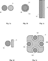
In dem in
Aufgrund der identischen Ausgestaltung der Kalibrierelektroden und der symmetrischen Anordnung der Kalibrierelektroden kann in dem ersten Betriebsmodus beispielsweise nur die Kalibrierelektrode K1 mit der ersten Kalibrierspannung UKAL1 und in dem zweiten Betriebsmodus nur die Kalibrierelektrode K2 mit der zweiten Kalibrierspannung UKAL2 beaufschlagt werden. Um eine bessere Funktion zu gewährleisten, ist es allerdings vorteilhaft, in beiden Betriebsmodi jeweils beide Kalibrierelektroden mit der entsprechenden Kalibrierspannung zu beaufschlagen.Due to the identical configuration of the calibration electrodes and the symmetrical arrangement of the calibration electrodes, in the first operating mode, for example, only the calibration electrode K1 can be acted upon by the first calibration voltage U KAL1 and in the second operating mode only by the calibration electrode K2 with the second calibration voltage U KAL2 . In order to ensure a better function, however, it is advantageous in both operating modes both calibration electrodes to apply the appropriate calibration voltage.
Erfindungsgemäß kann für jede einzelne Messelektrode M1 bis M4 unabhängig voneinander ermittelt werden, ob ein geeigneter Kalibrierzeitpunkt für die Kalibrierung der kapazitiven Sensoreinrichtung vorliegt. In einer Ausgestaltung der Erfindung kann die kapazitive Sensoreinrichtung kalibriert werden, wenn für alle vier Messelektroden M1 bis M4 die Bedingungen für eine Kalibrierung vorliegen. In einer anderen Ausgestaltung der Erfindung kann jede Messelektrode einzeln und unabhängig von den anderen Messelektroden kalibriert werden, d. h., das der jeweiligen Messelektrode zugehörige Sensor-Rohsignal wird unabhängig von den Sensor-Rohsignalen der übrigen Messelektroden kalibriert. Dies ist insbesondere dann von Vorteil, wenn die Messelektroden räumlich weit auseinander liegen und die Umgebungsbedingungen der weit auseinander liegenden Messelektroden jeweils verschieden sind.According to the invention, it can be determined independently for each individual measuring electrode M1 to M4 whether there is a suitable calibration time for the calibration of the capacitive sensor device. In one embodiment of the invention, the capacitive sensor device can be calibrated if the conditions for a calibration are present for all four measuring electrodes M1 to M4. In another embodiment of the invention, each measuring electrode can be calibrated individually and independently of the other measuring electrodes, i. That is, the sensor raw signal associated with the respective measuring electrode is calibrated independently of the raw sensor signals of the remaining measuring electrodes. This is particularly advantageous when the measuring electrodes are spatially far apart and the environmental conditions of the widely spaced measuring electrodes are different.
Kalibrierverfahren bzw. Verfahren zum Bestimmen eines Kalibrierzeitpunktes: Im Folgenden wird das Verfahren zum Kalibrieren einer kapazitiven Sensoreinrichtung bzw. zum Ermitteln eines günstigen Zeitpunktes für das Kalibrieren der kapazitiven Sensoreinrichtung näher beschrieben.Calibration method or method for determining a calibration time: The method for calibrating a capacitive sensor device or for determining a favorable time for calibrating the capacitive sensor device is described in more detail below.
Das erfindungsgemäße Verfahren wird anhand einer kapazitiven Sensoreinrichtung mit einer Messelektrode M und einer Kalibrierelektrode K erläutert, wobei das Verfahren auch für eine kapazitive Sensoreinrichtung mit einer Mehrzahl von Messelektroden und einer Mehrzahl von Kalibrierelektroden, welche den Messelektroden zugeordnet sind, ausgeführt werden kann. Ferner wird in der nachfolgenden Erläuterung des erfindungsgemäßen Verfahrens davon ausgegangen, dass zwei Betriebsmodi für den Betrieb der Kalibrierelektrode vorgesehen sind. Selbstverständlich kann das erfindungsgemäße Verfahren in entsprechender Weise auch dann angewandt werden, wenn mehr als zwei Betriebsmodi für den Betrieb der Kalibrierelektrode vorgesehen sind, wie bereits mit Bezug auf
Die Messelektrode und die Kalibrierelektrode sind beispielsweise derart ausgestaltet und relativ zueinander angeordnet, wie mit Bezug auf
In einem ersten Schritt wird die Kalibrierelektrode K in einem ersten Betriebsmodus B1 betrieben. In dem ersten Betriebsmodus B1 wird die Kalibrierelektrode K1 mit einer ersten Kalibrierspannung UKAL1 beaufschlagt und eine erste Kapazität zwischen der Messelektrode M und der Masse der Sensoreinrichtung detektiert, wobei Sensor-Rohdaten der Messelektrode M erfasst werden.In a first step, the calibration electrode K is operated in a first operating mode B1. In the first operating mode B1, the calibration electrode K1 is acted on by a first calibration voltage U KAL1 and a first capacitance between the measuring electrode M and the mass of the sensor device is detected, sensor raw data of the measuring electrode M being detected.
Anschließend wird in einem zweiten Schritt von dem ersten Betriebsmodus B1 in einen zweiten Betriebsmodus B2 zum Betrieb der Kalibrierelektrode K gewechselt. In dem zweiten Betriebsmodus B2 wird die Kalibrierelektrode K mit einer zweiten Kalibrierspannung UKAL2 beaufschlagt, welche verschieden von der ersten Kalibrierspannung UKAL1 des ersten Betriebsmodus B1 ist. Die erste Kalibrierspannung UKAL1 und die zweite Kalibrierspannung UKAL2 sind hierbei so zu wählen, wie mit Bezug auf
In einem weiteren Schritt des erfindungsgemäßen Verfahrens wird die Differenz der in den vorangegangenen Schritten gemessenen Sensor-Rohdaten ermittelt.In a further step of the method according to the invention, the difference of the sensor raw data measured in the preceding steps is determined.
Die Differenz zwischen den Sensor-Rohdaten in dem ersten Betriebsmodus und dem zweiten Betriebsmodus ist in
Ist die Differenz D betragsmäßig größer als ein vorbestimmter Schwellenwert X, wird davon ausgegangen, dass ein günstiger Zeitpunkt für die Kalibrierung der kapazitiven Sensoreinrichtung vorliegt, weil sich das Objekt nicht in der Nähe der Messelektrode befindet bzw. kein Objekt in der Nähe der Messelektrode vorhanden ist. In diesem Fall kann die Kalibrierung der kapazitiven Sensoreinrichtung initiiert bzw. durchgeführt werden.If the difference D is greater than a predetermined threshold value X, it is assumed that there is a favorable time for the calibration of the capacitive sensor device, because the object is not in the vicinity of the measuring electrode or there is no object in the vicinity of the measuring electrode , In this case, the calibration of the capacitive sensor device can be initiated or carried out.
Experimente haben gezeigt, dass keine nennenswerte Abhängigkeit der Differenz D von der Größe des Objektes besteht. Sollte diese Abhängigkeit dennoch bestehen, ist es dennoch möglich, zu entscheiden, ob sich ein Objekt in der Nähe der Messelektrode befindet, sodass eine Kalibrierung der kapazitiven Sensoreinrichtung in diesem Fall unterbleiben kann bzw. unterbunden werden kann.Experiments have shown that there is no significant dependence of the difference D on the size of the object. Should this dependence nevertheless exist, it is still possible to decide whether an object is located in the vicinity of the measuring electrode, so that a calibration of the capacitive sensor device in this case can be omitted or can be prevented.
Wie in
Die zuvor beschriebenen Schritte des erfindungsgemäßen Verfahrens können zu vorbestimmten Zeitpunkten bzw. zyklisch ausgeführt werden, sodass die Kalibrierung der kapazitiven Sensoreinrichtung gegebenenfalls an sich ändernde Umgebungsbedingungen angepasst werden kann.The above-described steps of the method according to the invention can be carried out at predetermined times or cyclically, so that the calibration of the capacitive sensor device can optionally be adapted to changing environmental conditions.
Für eine vorläufige bzw. provisorische Kalibrierung der Sensor-Rohdaten wird aus der Differenz D der Abstand A zum Objekt abgeschätzt und die dem Abstand entsprechenden kalibrierten Sensor-Rohdaten berechnet und für die Kalibrierung, d. h. für die vorläufige Kalibrierung, herangezogen, wobei die kalibrierten Sensor-Rohdaten von den aktuellen Sensor-Rohdaten abgezogen werden.For a preliminary or provisional calibration of the sensor raw data, the distance D to the object is estimated from the difference D and the calibrated sensor raw data corresponding to the distance is calculated and used for the calibration, ie. H. for the preliminary calibration, whereby the calibrated sensor raw data are subtracted from the current sensor raw data.
Das Maß, in dem sich die Sensor-Rohdaten der Messelektrode M beim Umschalten der Kalibrierelektrode K von dem ersten Betriebmodus in den zweiten Betriebsmodus ändern, wird im Wesentlichen durch die Kapazität von der Kalibrierelektrode K zur Messelektrode M bestimmt. In vielen Fällen sind die Elektroden M, K als Kupferflächen auf der Leiterplatte PCB ausgeführt. Die Abmessungen der Leiterplatte PCB können je nach verwendetem Leiterplattenmaterial bei Temperaturänderungen stark variieren. Infolgedessen kann auch die Kapazität von der Kalibrierelektrode K zur Messelektrode M je nach Elektrodenausführung einer ziemlich starken Temperaturabhängigkeit unterliegen.The extent to which the sensor raw data of the measuring electrode M changes when switching the calibration electrode K from the first operating mode to the second operating mode is essentially determined by the capacitance from the calibration electrode K to the measuring electrode M. In many cases, the electrodes M, K are designed as copper surfaces on the printed circuit board PCB. The dimensions of the printed circuit board PCB can vary greatly depending on the printed circuit board material used in the event of temperature changes. As a result, the capacitance from the calibration electrode K to the measurement electrode M may also be subject to a fairly strong temperature dependence depending on the electrode design.
Um die Temperaturabhängigkeit der Kapazität der Kalibrierelektrode zur Messelektrode zu minimieren bzw. weitestgehend zu eliminieren, sodass eine möglichst gleichbleibende Schätzung des Abstandes zwischen einem Objekt und der Messelektrode M unabhängig von der Umgebungstemperatur gewährleistet ist, kann ein Teil der Leiterplatte PCB zwischen der Messelektrode M und der Kalibrierelektrode K ausgefräst werden, sodass zwischen der Messelektrode M und der Kalibrierelektrode K eine Öffnung entsteht und sich im Wesentlichen kein Leiterplattenmaterial zwischen den Elektroden befindet.In order to minimize or largely eliminate the temperature dependence of the capacity of the calibration electrode to the measuring electrode, so that the most constant estimation of the distance between an object and the measuring electrode M is ensured regardless of the ambient temperature, a part of the circuit board PCB between the measuring electrode M and Calibration electrode K are milled out, so that between the measuring electrode M and the calibration K creates an opening and there is essentially no printed circuit board material between the electrodes.
Die erfindungsgemäße kapazitive Sensoreinrichtung bzw. das erfindungsgemäße Verfahren zur Kalibrierung der kapazitiven Sensoreinrichtung stellt eine verbesserte Entscheidungsgrundlage bereit, um zu bestimmen, ob eine Kalibrierung des kapazitiven Sensorsystems durchgeführt werden kann. Ferner kann eine provisorische bzw. vorläufige (ungefähre) Kalibrierung des kapazitiven Sensorsystems durchgeführt werden, etwa wenn die Bedingungen für eine Kalibrierung nicht geeignet sind, was beispielsweise dann der Fall ist, wenn sich ein Objekt nahe bzw. sehr nahe an der Messelektrode M befindet. Insgesamt wird es dadurch möglich, die kapazitive Sensoreinrichtung bereits unmittelbar nach der Aktivierung der Sensoreinrichtung zu kalibrieren, unabhängig davon, ob sich ein Objekt in der Nähe der Messelektrode befindet oder nicht. Die kapazitive Sensoreinrichtung kann so während der gesamten Dauer des Betriebes kalibriert sein bzw. kalibriert werden. Zeiträume, in denen die Sensor-Rohdaten unkalibriert einer weiteren Verarbeitung zugeführt werden, werden so effektiv vermieden, sodass eine gleichbleibende und korrekte Detektion einer Annäherung bzw. einer Berührung während der gesamten Betriebsdauer der kapazitiven Sensoreinrichtung gewährleistet werden kann.The capacitive sensor device according to the invention or the method according to the invention for calibrating the capacitive sensor device provides an improved decision basis for determining whether a calibration of the capacitive sensor system can be carried out. Furthermore, a provisional (approximate) calibration of the capacitive sensor system may be performed, for example, when the conditions for a calibration are not suitable, which is the case, for example, when an object is near or very close to the measuring electrode M. Overall, this makes it possible to calibrate the capacitive sensor device immediately after activation of the sensor device, regardless of whether an object is in the vicinity of the measuring electrode or not. The capacitive sensor device can thus be calibrated or calibrated during the entire duration of the operation. Periods in which the sensor raw data uncalibrated be supplied to further processing are effectively avoided, so that a consistent and correct detection of an approximation or a contact during the entire operating life of the capacitive sensor device can be ensured.
Bezugszeichenliste:LIST OF REFERENCE NUMBERS
-
- AA
- Abstand eines Objektes zu einer MesselektrodeDistance of an object to a measuring electrode
- COCO
- Aussparung (Cut-Out) der LeiterplatteCut-out of the printed circuit board
- DD
- Differenz der Sensor-Rohdaten zwischen im ersten Betriebsmodus und zweiten BetriebsmodusDifference of the sensor raw data between in the first operating mode and the second operating mode
- B1, B2B1, B2
- Betriebsmodi der Kalibrierelektroden bzw. der SensoreinrichtungOperating modes of the calibration electrodes and the sensor device
- K, K1, K2K, K1, K2
- Kalibrierelektrodencalibrating electrodes
- M, M1–M4M, M1-M4
- Messelektrodenmeasuring electrodes
- PCBPCB
- Leiterplattecircuit board
- UGEN U GEN
- Generatorspannung, welche einer Generatorelektrode beaufschlagt wirdGenerator voltage, which is applied to a generator electrode
- UKAL, UKAL1, UKAL2 U KAL , U KAL1 , U KAL2
- Kalibrierspannungen, welche den Kalibrierelektroden beaufschlagt werdenCalibration voltages which are applied to the calibration electrodes
- XX
- Schwellenwertthreshold
Claims (17)
Priority Applications (8)
| Application Number | Priority Date | Filing Date | Title |
|---|---|---|---|
| DE102011078369A DE102011078369B4 (en) | 2011-06-29 | 2011-06-29 | Capacitive sensor device and method for calibrating a capacitive sensor device |
| JP2014517723A JP6014131B2 (en) | 2011-06-29 | 2012-06-28 | Capacitive sensor device and method for calibrating a capacitive sensor device |
| US14/129,351 US9442175B2 (en) | 2011-06-29 | 2012-06-28 | Capacitive sensor device and method for calibrating a capacitive sensor device |
| CN201280039515.1A CN103748789B (en) | 2011-06-29 | 2012-06-28 | Capacitive sensor device and the method for calibration capacitance sensor device |
| KR1020147001769A KR101922014B1 (en) | 2011-06-29 | 2012-06-28 | Capacitive Sensor Device and Method for Calibrating a Capacitive Sensor Device |
| PCT/EP2012/062650 WO2013001047A1 (en) | 2011-06-29 | 2012-06-28 | Capacitive sensor device and method for calibrating a capacitive sensor device |
| EP12740512.4A EP2727243B1 (en) | 2011-06-29 | 2012-06-28 | Capacitive sensor device and method for calibrating a capacitive sensor device |
| TW101123657A TWI573393B (en) | 2011-06-29 | 2012-06-29 | Capacitive sensor device and method for calibrating a capacitive sensor device |
Applications Claiming Priority (1)
| Application Number | Priority Date | Filing Date | Title |
|---|---|---|---|
| DE102011078369A DE102011078369B4 (en) | 2011-06-29 | 2011-06-29 | Capacitive sensor device and method for calibrating a capacitive sensor device |
Publications (2)
| Publication Number | Publication Date |
|---|---|
| DE102011078369A1 DE102011078369A1 (en) | 2013-01-03 |
| DE102011078369B4 true DE102011078369B4 (en) | 2013-02-28 |
Family
ID=46583960
Family Applications (1)
| Application Number | Title | Priority Date | Filing Date |
|---|---|---|---|
| DE102011078369A Active DE102011078369B4 (en) | 2011-06-29 | 2011-06-29 | Capacitive sensor device and method for calibrating a capacitive sensor device |
Country Status (7)
| Country | Link |
|---|---|
| US (1) | US9442175B2 (en) |
| EP (1) | EP2727243B1 (en) |
| JP (1) | JP6014131B2 (en) |
| KR (1) | KR101922014B1 (en) |
| DE (1) | DE102011078369B4 (en) |
| TW (1) | TWI573393B (en) |
| WO (1) | WO2013001047A1 (en) |
Families Citing this family (6)
| Publication number | Priority date | Publication date | Assignee | Title |
|---|---|---|---|---|
| DE102011078369B4 (en) | 2011-06-29 | 2013-02-28 | Ident Technology Ag | Capacitive sensor device and method for calibrating a capacitive sensor device |
| WO2017158907A1 (en) * | 2016-03-15 | 2017-09-21 | オリンパス株式会社 | Touch panel device and touch panel device processing method |
| GB2550967A (en) | 2016-06-03 | 2017-12-06 | Brandenburg (Uk) Ltd | Sensing of objects |
| DE102018111380A1 (en) | 2017-05-24 | 2018-11-29 | HELLA GmbH & Co. KGaA | Method for calibrating at least one sensor |
| JP6948873B2 (en) * | 2017-07-31 | 2021-10-13 | 東京エレクトロン株式会社 | How to calibrate the measuring instrument and the case |
| KR102348131B1 (en) * | 2019-09-04 | 2022-01-06 | 평화오일씰공업 주식회사 | Automatic transmission with D-ring |
Citations (4)
| Publication number | Priority date | Publication date | Assignee | Title |
|---|---|---|---|---|
| DE4331555A1 (en) * | 1992-09-30 | 1994-03-31 | Siemens Ag | Adjustable inductive proximity switch - uses learning mode to determine required switch function in normal operating mode |
| DE202006015740U1 (en) * | 2006-10-13 | 2008-02-21 | Brose Fahrzeugteile Gmbh & Co. Kommanditgesellschaft, Coburg | anti-pinch |
| DE102008044067A1 (en) * | 2008-11-25 | 2010-05-27 | Huf Hülsbeck & Fürst Gmbh & Co. Kg | Capacitive proximity sensor with a shield electrode and a diagnostic electrode |
| DE102009057931A1 (en) * | 2009-12-11 | 2011-06-16 | Ident Technology Ag | Electrode arrangement system for electrical handheld device has transmission electrode and compensation electrode, which generate current in reception electrode representing approach of hand to handheld device |
Family Cites Families (19)
| Publication number | Priority date | Publication date | Assignee | Title |
|---|---|---|---|---|
| EP0425823A1 (en) * | 1989-09-29 | 1991-05-08 | Antivision Systems Corp. | Electrocstatic imaging apparatus |
| US5394097A (en) * | 1992-11-24 | 1995-02-28 | Bechtel; Friend K. | Dielectric sensor |
| US6825765B2 (en) * | 1998-12-30 | 2004-11-30 | Automotive Systems Laboratory, Inc. | Occupant detection system |
| ATE517426T1 (en) | 1999-01-26 | 2011-08-15 | Limited Qrg | CAPACITIVE TRANSDUCER AND ARRANGEMENT |
| DE10251639A1 (en) | 2002-10-31 | 2004-05-13 | E.G.O. Elektro-Gerätebau GmbH | Sensor element device for a capacitive touch switch with an electrically conductive body and method for producing such a body |
| DE10323030A1 (en) | 2003-05-20 | 2004-12-09 | Stefan Reich | Capacitive sensor for multiple applications measures values that influence the capacitance of a measurement space by measuring the capacitive coupling between two electrodes and relating it to a physical value |
| JP4310695B2 (en) | 2004-03-30 | 2009-08-12 | アイシン精機株式会社 | Capacitance change detection device |
| US7839282B1 (en) * | 2006-12-27 | 2010-11-23 | The United States Of America As Represented By The United States Department Of Energy | Capacitance probe for detection of anomalies in non-metallic plastic pipe |
| CN101849217B (en) * | 2008-04-25 | 2013-12-11 | 艾登特科技股份公司 | Electrode system for proximity detection and hand-held device with electrode system |
| DE102008029205A1 (en) * | 2008-06-19 | 2009-12-24 | Jungheinrich Aktiengesellschaft | Truck with optical lift height measurement |
| IT1393473B1 (en) * | 2009-03-10 | 2012-04-20 | Microtec Srl | METHOD OF CALIBRATION FOR EQUIPMENT FOR THE DETERMINATION OF THE DEGREE OF HUMIDITY OF PRODUCTS ON THE BASIS OF CAPACITIVE MEASURES, AND DEVICE FOR THE SIMULATION OF THE DIELECTRIC PROPERTIES OF PRODUCTS, SUCH AS WOOD, TO BE USED IN THIS METHOD. |
| WO2010115940A1 (en) * | 2009-04-07 | 2010-10-14 | Ident Technology Ag | Sensor device and method for grip and proximity detection |
| JP2010257046A (en) * | 2009-04-22 | 2010-11-11 | Mitsubishi Electric Corp | Proximity detection device |
| DE102009061064B4 (en) | 2009-07-08 | 2013-11-28 | Ident Technology Ag | Detection device for an electrical hand-held device and hand-held device with a detection device |
| DE102009057935B4 (en) * | 2009-12-11 | 2015-07-09 | Ident Technology Ag | Device and method for detecting gripping of a handheld device by a hand |
| DE102009057933B3 (en) * | 2009-12-11 | 2011-02-24 | Ident Technology Ag | Sensor device for detecting approach and touch of e.g. hand held device by hand, has electrode structure including transmission, compensation and receiving electrodes, where electrical field is received in receiving electrode |
| US8590377B2 (en) * | 2010-02-08 | 2013-11-26 | Massachusetts Institute Of Technology | Inertial measurement unit |
| JP2011170617A (en) * | 2010-02-18 | 2011-09-01 | On Semiconductor Trading Ltd | Electrostatic capacity type touch sensor |
| DE102011078369B4 (en) | 2011-06-29 | 2013-02-28 | Ident Technology Ag | Capacitive sensor device and method for calibrating a capacitive sensor device |
-
2011
- 2011-06-29 DE DE102011078369A patent/DE102011078369B4/en active Active
-
2012
- 2012-06-28 US US14/129,351 patent/US9442175B2/en active Active
- 2012-06-28 WO PCT/EP2012/062650 patent/WO2013001047A1/en active Application Filing
- 2012-06-28 JP JP2014517723A patent/JP6014131B2/en not_active Expired - Fee Related
- 2012-06-28 KR KR1020147001769A patent/KR101922014B1/en active IP Right Grant
- 2012-06-28 EP EP12740512.4A patent/EP2727243B1/en not_active Not-in-force
- 2012-06-29 TW TW101123657A patent/TWI573393B/en not_active IP Right Cessation
Patent Citations (4)
| Publication number | Priority date | Publication date | Assignee | Title |
|---|---|---|---|---|
| DE4331555A1 (en) * | 1992-09-30 | 1994-03-31 | Siemens Ag | Adjustable inductive proximity switch - uses learning mode to determine required switch function in normal operating mode |
| DE202006015740U1 (en) * | 2006-10-13 | 2008-02-21 | Brose Fahrzeugteile Gmbh & Co. Kommanditgesellschaft, Coburg | anti-pinch |
| DE102008044067A1 (en) * | 2008-11-25 | 2010-05-27 | Huf Hülsbeck & Fürst Gmbh & Co. Kg | Capacitive proximity sensor with a shield electrode and a diagnostic electrode |
| DE102009057931A1 (en) * | 2009-12-11 | 2011-06-16 | Ident Technology Ag | Electrode arrangement system for electrical handheld device has transmission electrode and compensation electrode, which generate current in reception electrode representing approach of hand to handheld device |
Also Published As
| Publication number | Publication date |
|---|---|
| US9442175B2 (en) | 2016-09-13 |
| CN103748789A (en) | 2014-04-23 |
| EP2727243A1 (en) | 2014-05-07 |
| TWI573393B (en) | 2017-03-01 |
| KR20140053122A (en) | 2014-05-07 |
| US20140292351A1 (en) | 2014-10-02 |
| TW201320599A (en) | 2013-05-16 |
| DE102011078369A1 (en) | 2013-01-03 |
| KR101922014B1 (en) | 2018-11-27 |
| EP2727243B1 (en) | 2018-05-02 |
| JP6014131B2 (en) | 2016-10-25 |
| JP2014527325A (en) | 2014-10-09 |
| WO2013001047A1 (en) | 2013-01-03 |
Similar Documents
| Publication | Publication Date | Title |
|---|---|---|
| DE102011078369B4 (en) | Capacitive sensor device and method for calibrating a capacitive sensor device | |
| DE102009057439B4 (en) | Device and method for error-free capacitive measured value acquisition | |
| DE102009057933B3 (en) | Sensor device for detecting approach and touch of e.g. hand held device by hand, has electrode structure including transmission, compensation and receiving electrodes, where electrical field is received in receiving electrode | |
| DE102009057935B4 (en) | Device and method for detecting gripping of a handheld device by a hand | |
| EP3166228B1 (en) | Sensor module, sensor system and method for capacitive and spatially resolved detection of approaching and contact, use of the sensor module | |
| DE102011003734B3 (en) | Electrode configuration for a capacitive sensor device and capacitive sensor device for approach detection | |
| DE102008057823A1 (en) | Capacitive sensor system | |
| DE102011006079A1 (en) | Measuring device and method for approach detection | |
| WO2009047073A1 (en) | Sensor device for capacitive distance determination | |
| EP3746747B1 (en) | Capacitive measuring system | |
| EP2759812B1 (en) | Method and apparatus for capacitative fill level measurement of liquids or bulk materials | |
| DE10256064A1 (en) | Method and device for determining the water content and conductivity in soils and bulk materials | |
| DE10110724A1 (en) | Fingerprint sensor with potential modulation of the ESD protective grid | |
| DE102010030959B4 (en) | Sensor device and method for detecting a gripping of a hand-held device and a hand-held device | |
| DE10121008B4 (en) | Capacitive keyboard with evaluation circuit | |
| DE102007003887A1 (en) | Method for operating a device for the capacitive determination and / or monitoring of a process variable | |
| EP3373403A1 (en) | Differential current protection and operation method for detecting a voltage on the pen conductor | |
| EP3118591B1 (en) | Fill level measurement device | |
| DE102005027344A1 (en) | Capacitive level measuring or detection device | |
| DE102009057931B4 (en) | Circuit arrangement for a capacitive sensor element. | |
| DE102011002603B4 (en) | Capacitive sensor device and method for operating a capacitive sensor device | |
| DE102011002446A1 (en) | Sensor device and method for capacitive proximity detection | |
| DE102009053077B3 (en) | Capacitive proximity sensor arrangement for use in rolling mill, has coil that is connected in series or parallel to capacitor i.e. source-gate capacitor, between control port and output terminal of input transistor | |
| DE102009032357B3 (en) | Electrode arrangement system for electrical handheld device has transmission electrode and compensation electrode, which generate current in reception electrode representing approach of hand to handheld device | |
| DE102015015534B4 (en) | Touch-sensitive operating device with air condensers and flexible printed circuit board |
Legal Events
| Date | Code | Title | Description |
|---|---|---|---|
| R012 | Request for examination validly filed | ||
| R081 | Change of applicant/patentee |
Owner name: MICROCHIP TECHNOLOGY GERMANY GMBH, DE Free format text: FORMER OWNER: IDENT TECHNOLOGY AG, 82205 GILCHING, DE |
|
| R082 | Change of representative |
Representative=s name: BETTINGER SCHNEIDER SCHRAMM PATENT- UND RECHTS, DE Representative=s name: 2S-IP SCHRAMM SCHNEIDER PATENTANWAELTE - RECHT, DE Representative=s name: 2S-IP SCHRAMM SCHNEIDER BERTAGNOLL PATENT- UND, DE |
|
| R016 | Response to examination communication | ||
| R016 | Response to examination communication | ||
| R018 | Grant decision by examination section/examining division | ||
| R020 | Patent grant now final |
Effective date: 20130529 |
|
| R082 | Change of representative |
Representative=s name: 2S-IP SCHRAMM SCHNEIDER PATENTANWAELTE - RECHT, DE Representative=s name: 2S-IP SCHRAMM SCHNEIDER BERTAGNOLL PATENT- UND, DE |
|
| R081 | Change of applicant/patentee |
Owner name: NEODRON LIMITED, IE Free format text: FORMER OWNER: IDENT TECHNOLOGY AG, 82205 GILCHING, DE Owner name: MICROCHIP TECHNOLOGY GERMANY GMBH, DE Free format text: FORMER OWNER: IDENT TECHNOLOGY AG, 82205 GILCHING, DE |
|
| R082 | Change of representative |
Representative=s name: PETERREINS SCHLEY PATENT- UND RECHTSANWAELTE, DE Representative=s name: PETERREINS SCHLEY PATENT- UND RECHTSANWAELTE P, DE Representative=s name: 2S-IP SCHRAMM SCHNEIDER PATENTANWAELTE - RECHT, DE Representative=s name: 2S-IP SCHRAMM SCHNEIDER BERTAGNOLL PATENT- UND, DE |
|
| R081 | Change of applicant/patentee |
Owner name: NEODRON LIMITED, IE Free format text: FORMER OWNER: MICROCHIP TECHNOLOGY GERMANY GMBH, 82205 GILCHING, DE |
|
| R082 | Change of representative |
Representative=s name: PETERREINS SCHLEY PATENT- UND RECHTSANWAELTE, DE Representative=s name: PETERREINS SCHLEY PATENT- UND RECHTSANWAELTE P, DE |