DE102010045532B4 - Roboterdaumenanodnung - Google Patents
Roboterdaumenanodnung Download PDFInfo
- Publication number
- DE102010045532B4 DE102010045532B4 DE102010045532A DE102010045532A DE102010045532B4 DE 102010045532 B4 DE102010045532 B4 DE 102010045532B4 DE 102010045532 A DE102010045532 A DE 102010045532A DE 102010045532 A DE102010045532 A DE 102010045532A DE 102010045532 B4 DE102010045532 B4 DE 102010045532B4
- Authority
- DE
- Germany
- Prior art keywords
- phalanx
- axis
- joint
- phalange
- tendons
- Prior art date
- Legal status (The legal status is an assumption and is not a legal conclusion. Google has not performed a legal analysis and makes no representation as to the accuracy of the status listed.)
- Expired - Fee Related
Links
Images


Classifications
-
- B—PERFORMING OPERATIONS; TRANSPORTING
- B25—HAND TOOLS; PORTABLE POWER-DRIVEN TOOLS; MANIPULATORS
- B25J—MANIPULATORS; CHAMBERS PROVIDED WITH MANIPULATION DEVICES
- B25J15/00—Gripping heads and other end effectors
- B25J15/0009—Gripping heads and other end effectors comprising multi-articulated fingers, e.g. resembling a human hand
-
- B—PERFORMING OPERATIONS; TRANSPORTING
- B25—HAND TOOLS; PORTABLE POWER-DRIVEN TOOLS; MANIPULATORS
- B25J—MANIPULATORS; CHAMBERS PROVIDED WITH MANIPULATION DEVICES
- B25J9/00—Programme-controlled manipulators
- B25J9/10—Programme-controlled manipulators characterised by positioning means for manipulator elements
- B25J9/104—Programme-controlled manipulators characterised by positioning means for manipulator elements with cables, chains or ribbons
-
- Y—GENERAL TAGGING OF NEW TECHNOLOGICAL DEVELOPMENTS; GENERAL TAGGING OF CROSS-SECTIONAL TECHNOLOGIES SPANNING OVER SEVERAL SECTIONS OF THE IPC; TECHNICAL SUBJECTS COVERED BY FORMER USPC CROSS-REFERENCE ART COLLECTIONS [XRACs] AND DIGESTS
- Y10—TECHNICAL SUBJECTS COVERED BY FORMER USPC
- Y10T—TECHNICAL SUBJECTS COVERED BY FORMER US CLASSIFICATION
- Y10T74/00—Machine element or mechanism
- Y10T74/20—Control lever and linkage systems
- Y10T74/20207—Multiple controlling elements for single controlled element
- Y10T74/20305—Robotic arm
- Y10T74/20329—Joint between elements
Landscapes
- Engineering & Computer Science (AREA)
- Robotics (AREA)
- Mechanical Engineering (AREA)
- Manipulator (AREA)
- Measurement Of Length, Angles, Or The Like Using Electric Or Magnetic Means (AREA)
Abstract
Roboterhandanordnung (18), die umfasst: eine Basisstruktur (34); erste (38A), zweite (38B), dritte (38C) und vierte (38D) Fingerglieder; ein erstes Gelenk (42A), welches das erste Fingerglied (38A) mit der Basisstruktur (34) auf funktionale Weise derart verbindet, dass das erste Fingerglied (38A) mit Bezug auf die Basisstruktur (34) um eine erste Achse (A1) selektiv drehbar ist; ein zweites Gelenk (42B), welches das zweite Fingerglied (38B) mit dem ersten Fingerglied (38A) auf funktionale Weise derart verbindet, dass das zweite Fingerglied (38B) mit Bezug auf das erste Fingerglied (38A) um eine zweite Achse (A2) selektiv drehbar ist; ein drittes Gelenk (42C), welches das dritte Fingerglied (38C) mit dem zweiten Fingerglied (38B) auf funktionale Weise derart verbindet, dass das dritte Fingerglied (38C) mit Bezug auf das zweite Fingerglied (38B) um eine dritte Achse (A3) selektiv drehbar ist; und ein viertes Gelenk (42D), welches das vierte Fingerglied (38D) mit dem...A robotic hand assembly (18) comprising: a base structure (34); first (38A), second (38B), third (38C) and fourth (38D) phalanges; a first hinge (42A) operatively connecting the first phalange (38A) to the base structure (34) such that the first phalange (38A) is selectively rotatable relative to the base structure (34) about a first axis (A1) is; a second hinge (42B) operatively connecting the second phalange (38B) to the first phalange (38A) such that the second phalange (38B) is rotatable about a second axis (A2) with respect to the first phalange (38A); is selectively rotatable; a third joint (42C) operatively connecting the third phalange (38C) to the second phalange (38B) such that the third phalange (38C) is rotatable about a third axis (A3) with respect to the second phalange (38B); is selectively rotatable; and a fourth joint (42D) which connects the fourth phalange (38D) to the ...
Description
Diese Erfindung wurde mit Regierungsunterstützung unter dem NASA Space Act Agreement mit der Nummer SAA-AT-07-003 durchgeführt. Die Regierung kann einige Rechte an der Erfindung besitzen.This invention was performed with government support under the NASA Space Act Agreement number SAA-AT-07-003. The government may have some rights to the invention.
TECHNISCHES GEBIETTECHNICAL AREA
Die vorliegende Erfindung betrifft Roboterhände und insbesondere Roboterdaumen.The present invention relates to robotic hands, and more particularly to robotic thumbs.
HINTERGRUND DER ERFINDUNGBACKGROUND OF THE INVENTION
Typische Roboter sind automatisierte Einrichtungen, die zur Manipulation von Objekten unter Verwendung einer Reihe von starren Gliedern in der Lage sind, welche wiederum über Gelenkverbindungen oder motorgetriebene Robotergelenke miteinander verbunden sind. Jedes Gelenk in einem typischen Roboter stellt eine unabhängige Steuerungsvariable dar, die auch als ein Freiheitsgrad (DOF) bezeichnet wird. Greiforgane sind die speziellen Glieder, die zum Ausführen einer anstehenden Aufgabe verwendet werden, z. B. zum Ergreifen eines Arbeitswerkzeugs oder eines Objekts. Daher kann eine präzise Bewegungssteuerung eines Roboters durch die Ebene der Aufgabenbeschreibung gegliedert sein: eine Steuerung auf Objektebene, d. h. die Fähigkeit zur Steuerung des Verhaltens eines Objekts, das in einem Einzelgriff oder einem zusammenwirkenden Griff eines Roboters gehalten wird, eine Greiforgansteuerung, und eine Steuerung auf Gelenkebene. Die verschiedenen Steuerungsebenen arbeiten zusammen, um gemeinsam die erforderliche Mobilität, Geschicklichkeit und arbeitsaufgabenbezogene Funktionalität des Roboters zu erreichen.Typical robots are automated devices capable of manipulating objects using a series of rigid links which in turn are interconnected via articulated joints or motor-driven robotic joints. Each joint in a typical robot represents an independent control variable, also referred to as a degree of freedom (DOF). Greiforgane are the special links that are used to carry out a pending task, eg. For gripping a work tool or an object. Therefore, a precise motion control of a robot can be structured by the level of task description: object-level control, i. H. the ability to control the behavior of an object held in a single grip or cooperative grip of a robot, a jaw control, and joint-level control. The various levels of control work together to jointly achieve the required mobility, dexterity, and work-related functionality of the robot.
Humanoide Roboter sind insbesondere Roboter, die eine annähernd menschliche Gestalt oder ein annähernd menschliches Erscheinungsbild aufweisen, sei es ein vollständiger Körper, ein Torso und/oder eine Gliedmaße, wobei die strukturelle Komplexität des humanoiden Roboters zu einem großen Teil von dem Wesen der Arbeitsaufgabe abhängt, die ausgeführt wird. Die Verwendung humanoider Roboter kann dort bevorzugt sein, wo eine direkte Interaktion mit Einrichtungen oder Systemen benötigt wird, die speziell für den menschlichen Gebrauch hergestellt sind. Aufgrund des weiten Spektrums von Arbeitsaufgaben, die möglicherweise von einem humanoiden Roboter erwartet werden, können unterschiedliche Steuerungsmodi gleichzeitig benötigt werden. Zum Beispiel muss eine präzise Steuerung in den verschiedenen vorstehend angegebenen Räumen sowie eine Kontrolle über das angewandte Drehmoment oder die angewandte Kraft, die Bewegung und die verschiedenen Grifftypen angewendet werden.In particular, humanoid robots are robots having an approximate human shape or appearance, be it a complete body, a torso, and / or a limb, where the structural complexity of the humanoid robot is largely dependent on the nature of the work task. which is being executed. The use of humanoid robots may be preferred where direct interaction with equipment or systems made specifically for human use is needed. Due to the wide range of work tasks that may be expected of a humanoid robot, different control modes may be needed simultaneously. For example, precise control in the various spaces noted above, as well as control over the applied torque or force, motion, and the various types of handles must be used.
In
In
In
Die Aufgabe der Erfindung besteht darin, eine möglichst kompakte Roboterhandanordnung bereitzustellen, die eine unabhängige Steuerung eines Drehmoments an allen Fingergelenken eines Daumens der Roboterhandanordnung ermöglicht.The object of the invention is to provide as compact a robot hand arrangement as possible, which enables independent control of a torque at all finger joints of a thumb of the robot hand arrangement.
Diese Aufgabe wird durch die Roboterhandanordnung gemäß Anspruch 1 gelöst.This object is achieved by the robot hand arrangement according to claim 1.
ZUSAMMENFASSUNG DER ERFINDUNGSUMMARY OF THE INVENTION
Gemäß einem erster Aspekt der Offenbarung umfasst eine Roboterhandanordnung eine Basisstruktur, erste, zweite, dritte und vierte Fingerglieder und erste, zweite, dritte und vierte Gelenke. Das erste Gelenk verbindet das erste Fingerglied auf funktionale Weise derart mit der Basisstruktur, dass das erste Fingerglied mit Bezug auf die Basisstruktur um eine erste Achse selektiv drehbar ist. Das zweite Gelenk verbindet das zweite Fingerglied auf funktionale Weise derart mit dem ersten Fingerglied, dass das zweite Fingerglied mit Bezug auf das erste Fingerglied um eine zweite Achse selektiv drehbar ist. Das dritte Gelenk verbindet das dritte Fingerglied auf funktionale Weise derart mit dem zweiten Fingerglied, dass das dritte Fingerglied mit Bezug auf das zweite Fingerglied um eine dritte Achse selektiv drehbar ist. Das vierte Gelenk verbindet das vierte Fingerglied auf funktionale Weise derart mit dem dritten Fingerglied, dass das vierte Fingerglied mit Bezug auf das dritte Fingerglied um eine vierte Achse selektiv drehbar ist.According to a first aspect of the disclosure, a robotic hand arrangement comprises a base structure, first, second, third and fourth phalanges and first, second, third and fourth joints. The first hinge operatively connects the first phalange to the base structure such that the first phalange is selectively rotatable about a first axis with respect to the base structure. The second joint operatively connects the second phalange to the first phalange such that the second phalange is selectively rotatable about a second axis with respect to the first phalange. The third joint operatively connects the third phalange to the second phalange such that the third phalange is selectively rotatable about a third axis with respect to the second phalange. The fourth joint operatively connects the fourth phalange to the third phalange such that the fourth phalange is selectively rotatable about a fourth axis with respect to the third phalange.
Fünf Sehnen sind mit den Fingergliedern funktional verbunden, um darauf selektiv eine Kraft auszuüben und dadurch ein Drehmoment an den Gelenken zu erzeugen. Die Sehnen sind derart ausgestaltet, dass das Drehmoment an jedem der ersten, zweiten, dritten und vierten Gelenke durch die fünf Sehnen unabhängig steuerbar ist.Five tendons are operatively connected to the phalanges to selectively apply a force thereon and thereby produce a torque at the joints. The tendons are configured such that the torque at each of the first, second, third and fourth joints is independently controllable by the five tendons.
Die ersten vier Sehnen sind an einer ersten Seite der zweiten Achse derart verlegt, dass die Spannung in diesen vier Sehnen aufsummiert wird, um ein Greifmoment am zweiten Gelenk zu maximieren. Zudem ist die fünfte Sehne an einer zweiten Seite der zweiten Achse gegenüber der ersten Seite der zweiten Achse so verlegt, dass sie den ersten vier Sehnen zum Öffnen des zweiten Gelenks entgegenwirkt.The first four tendons are laid on a first side of the second axis such that the tension in these four tendons is summed to maximize a gripping moment on the second joint. In addition, the fifth tendon on a second side of the second axis opposite the first side of the second axis is laid so that it counteracts the first four tendons for opening the second joint.
Gemäß einem zweiten Aspekt der Erfindung umfasst eine Roboterhandanordnung eine Basisstruktur, erste, zweite, dritte und vierte Fingerglieder und erste, zweite, dritte und vierte Gelenke. Das erste Gelenk verbindet das erste Fingerglied auf funktionale Weise derart mit der Basisstruktur, dass das erste Fingerglied mit Bezug auf die Basisstruktur um eine erste Achse selektiv drehbar ist. Das zweite Gelenk verbindet das zweite Fingerglied auf funktionale Weise derart mit dem ersten Fingerglied, dass das zweite Fingerglied mit Bezug auf das erste Fingerglied um eine zweite Achse selektiv drehbar ist. Das dritte Gelenk verbindet das dritte Fingerglied auf funktionale Weise derart mit dem zweiten Fingerglied, dass das dritte Fingerglied mit Bezug auf das zweite Fingerglied um eine dritte Achse selektiv drehbar ist. Das vierte Gelenk verbindet das vierte Fingerglied auf funktionale Weise derart mit dem dritten Fingerglied, dass das vierte Fingerglied mit Bezug auf das dritte Fingerglied um eine vierte Achse selektiv drehbar ist. Die dritte und vierte Achse verlaufen im Wesentlichen parallel zueinander. Das zweite Fingerglied ist durch eine Verdrehung derart gekennzeichnet, dass die zweite Achse zu der dritten und vierten Achse nicht parallel verläuft. Die Verdrehung ersetzt einen der fünf Freiheitsgrade einer menschlichen Hand durch die Verdrehung in der Gestalt des zweiten Fingerglieds.According to a second aspect of the invention, a robotic hand assembly comprises a base structure, first, second, third and fourth phalanges and first, second, third and fourth joints. The first hinge operatively connects the first phalange to the base structure such that the first phalange is selectively rotatable about a first axis with respect to the base structure. The second joint operatively connects the second phalange to the first phalange such that the second phalange is selectively rotatable about a second axis with respect to the first phalange. The third joint operatively connects the third phalange to the second phalange such that the third phalange is selectively rotatable about a third axis with respect to the second phalange. The fourth joint operatively connects the fourth phalange to the third phalange such that the fourth phalange is selectively rotatable about a fourth axis with respect to the third phalange. The third and fourth axes are substantially parallel to each other. The second phalanx is characterized by a twist such that the second axis is not parallel to the third and fourth axes. The twist replaces one of the five degrees of freedom of a human hand with the twist in the shape of the second phalange.
Die vorstehenden Merkmale und Vorteile und andere Merkmale und Vorteile der vorliegenden Erfindung ergeben sich leicht aus der folgenden genauen Beschreibung der besten Arten zum Ausführen der Erfindung, wenn sie in Verbindung mit den beiliegenden Zeichnungen gelesen wird.The foregoing features and advantages and other features and advantages of the present invention will be readily apparent from the following detailed description of the best modes for carrying out the invention when taken in connection with the accompanying drawings.
KURZBESCHREIBUNG DER ZEICHNUNGENBRIEF DESCRIPTION OF THE DRAWINGS
BESCHREIBUNG DER BEVORZUGTEN AUSFÜHRUNGSFORMDESCRIPTION OF THE PREFERRED EMBODIMENT
Mit Bezug auf die Zeichnungen, in denen gleiche Bezugszeichen in den verschiedenen Ansichten gleiche oder ähnliche Komponenten bezeichnen, zeigt
Der humanoide Roboter
Gemäß einer Ausführungsform ist der Roboter
Der Arm
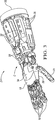
Mit Bezug auf
Der Oberarm
Bei der dargestellten Ausführungsform ist der Daumen
Mit Bezug auf
Der Daumen
Insbesondere wurde einer der fünf Freiheitsgrade des menschlichen Daumens, nämlich die dynamische Verdrehung zwischen den Achsen A2 und A3 im Roboterdaumen
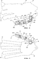
Mit Bezug auf
Jede der Gelenkpositionssensoranordnungen
Der Sensor
Der Magnet
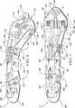
Mit Bezug auf
Das Verlegen der Sehnen
Ein Ende der Sehne
Die Sehne
Das Verlegen der Sehnen
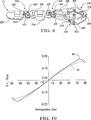
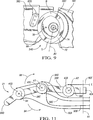
Mit Bezug auf
Mit der in
Obwohl die Sehnen
Obwohl in
Bei der dargestellten Ausführungsform beträgt der Bewegungsbereich des Gelenks
Obwohl die besten Arten zum Ausführen der Erfindung im Detail beschrieben wurden, werden Fachleute auf dem Gebiet, das diese Erfindung betrifft, verschiedene alternative Entwürfe und Ausführungsformen zum Umsetzen der Erfindung in die Praxis im Umfang der beigefügten Ansprüche erkennen.Although the best modes for carrying out the invention have been described in detail, those skilled in the art to which this invention relates will recognize various alternative designs and embodiments for practicing the invention within the scope of the appended claims.
Claims (4)
Applications Claiming Priority (2)
| Application Number | Priority Date | Filing Date | Title |
|---|---|---|---|
| US12/564,085 US8424941B2 (en) | 2009-09-22 | 2009-09-22 | Robotic thumb assembly |
| US12/564,085 | 2009-09-22 |
Publications (2)
| Publication Number | Publication Date |
|---|---|
| DE102010045532A1 DE102010045532A1 (en) | 2011-05-19 |
| DE102010045532B4 true DE102010045532B4 (en) | 2013-01-17 |
Family
ID=43755469
Family Applications (1)
| Application Number | Title | Priority Date | Filing Date |
|---|---|---|---|
| DE102010045532A Expired - Fee Related DE102010045532B4 (en) | 2009-09-22 | 2010-09-15 | Roboterdaumenanodnung |
Country Status (3)
| Country | Link |
|---|---|
| US (1) | US8424941B2 (en) |
| JP (2) | JP5357847B2 (en) |
| DE (1) | DE102010045532B4 (en) |
Families Citing this family (59)
| Publication number | Priority date | Publication date | Assignee | Title |
|---|---|---|---|---|
| FR2930905B1 (en) * | 2008-05-09 | 2010-10-01 | Bia | ANKLE FOR HUMANOIDE ROBOT |
| US7881965B2 (en) | 2008-10-02 | 2011-02-01 | ecoATM, Inc. | Secondary market and vending system for devices |
| US9881284B2 (en) | 2008-10-02 | 2018-01-30 | ecoATM, Inc. | Mini-kiosk for recycling electronic devices |
| CA2739633C (en) | 2008-10-02 | 2016-06-21 | Mark Bowles | Secondary market and vending system for devices |
| US10853873B2 (en) | 2008-10-02 | 2020-12-01 | Ecoatm, Llc | Kiosks for evaluating and purchasing used electronic devices and related technology |
| US11010841B2 (en) | 2008-10-02 | 2021-05-18 | Ecoatm, Llc | Kiosk for recycling electronic devices |
| EP2383082B1 (en) * | 2008-12-03 | 2015-10-07 | National University Corporation Nara Institute of Science and Technology | Robot hand |
| US8364314B2 (en) * | 2009-04-30 | 2013-01-29 | GM Global Technology Operations LLC | Method and apparatus for automatic control of a humanoid robot |
| US8483880B2 (en) * | 2009-07-22 | 2013-07-09 | The Shadow Robot Company Limited | Robotic hand |
| EP2695126A4 (en) | 2011-04-06 | 2014-09-17 | Ecoatm Inc | Method and kiosk for recycling electronic devices |
| DE102011007609B4 (en) | 2011-04-18 | 2020-03-19 | Kuka Deutschland Gmbh | Machine with links rotatable relative to each other |
| CA2853349A1 (en) * | 2011-10-25 | 2013-05-02 | ecoATM, Inc. | Method and apparatus for recycling electronic devices |
| EP2771792A4 (en) * | 2011-10-25 | 2015-09-02 | Ecoatm Inc | Method and apparatus for recycling electronic devices |
| KR101438971B1 (en) * | 2012-12-27 | 2014-09-15 | 현대자동차주식회사 | Grippper of robot and method for controlling the same |
| US9669551B1 (en) * | 2013-04-30 | 2017-06-06 | Sandia Corporation | Robotic hand and fingers |
| US11051892B2 (en) | 2013-09-20 | 2021-07-06 | Canon U.S.A., Inc. | Control apparatus and tendon-driven device |
| GB2519993B (en) * | 2013-11-04 | 2017-05-10 | The Shadow Robot Company Ltd | Robotic hand |
| CN103753526B (en) * | 2013-12-30 | 2015-09-30 | 重庆交通大学 | Can the precise heavy-load manipulator of positioning compensation |
| US9505134B2 (en) | 2014-04-21 | 2016-11-29 | GM Global Technology Operations LLC | Lower robotic arm assembly having a plurality of tendon driven digits |
| US20160052130A1 (en) * | 2014-08-25 | 2016-02-25 | Paul Ekas | Link structure and assembly including cable guide system for robotic mechanical manipulator structure |
| US10401411B2 (en) | 2014-09-29 | 2019-09-03 | Ecoatm, Llc | Maintaining sets of cable components used for wired analysis, charging, or other interaction with portable electronic devices |
| EP3201846A1 (en) | 2014-10-02 | 2017-08-09 | Ecoatm Inc. | Wireless-enabled kiosk for recycling consumer devices |
| WO2016054435A1 (en) | 2014-10-02 | 2016-04-07 | ecoATM, Inc. | Application for device evaluation and other processes associated with device recycling |
| US10445708B2 (en) | 2014-10-03 | 2019-10-15 | Ecoatm, Llc | System for electrically testing mobile devices at a consumer-operated kiosk, and associated devices and methods |
| FR3027246B1 (en) * | 2014-10-16 | 2019-04-12 | Centre National De La Recherche Scientifique (Cnrs) | MODULAR ROBOTIC FINGER FOR PREHENDING AND HANDLING DEXTRE |
| US10572946B2 (en) | 2014-10-31 | 2020-02-25 | Ecoatm, Llc | Methods and systems for facilitating processes associated with insurance services and/or other services for electronic devices |
| US10417615B2 (en) | 2014-10-31 | 2019-09-17 | Ecoatm, Llc | Systems and methods for recycling consumer electronic devices |
| CA3227945A1 (en) | 2014-11-06 | 2016-05-12 | Ecoatm, Llc | Methods and systems for evaluating and recycling electronic devices |
| WO2016094789A1 (en) | 2014-12-12 | 2016-06-16 | ecoATM, Inc. | Systems and methods for recycling consumer electronic devices |
| CN104528378B (en) * | 2014-12-26 | 2016-08-24 | 中国重型机械研究院股份公司 | A kind of card pipe feeding structure and method |
| CN104802180B (en) * | 2015-04-09 | 2017-06-06 | 上海大学 | Drive lacking anthropomorphic three refers to manipulator |
| JP7068165B2 (en) | 2015-10-15 | 2022-05-16 | キヤノン ユーエスエイ,インコーポレイテッド | Operable medical equipment |
| US10127647B2 (en) | 2016-04-15 | 2018-11-13 | Ecoatm, Llc | Methods and systems for detecting cracks in electronic devices |
| US9885672B2 (en) | 2016-06-08 | 2018-02-06 | ecoATM, Inc. | Methods and systems for detecting screen covers on electronic devices |
| US10269110B2 (en) | 2016-06-28 | 2019-04-23 | Ecoatm, Llc | Methods and systems for detecting cracks in illuminated electronic device screens |
| CN107471243B (en) * | 2017-07-26 | 2019-08-16 | 清华大学 | A kind of more perception apery five-needle pines blister rusts |
| JP6545768B2 (en) | 2017-10-02 | 2019-07-17 | スキューズ株式会社 | Finger mechanism, robot hand and control method of robot hand |
| CN107598960B (en) * | 2017-11-03 | 2023-09-19 | 西安广源机电技术有限公司 | Bionic manipulator easy to drive in full freedom degree |
| JP6634430B2 (en) | 2017-11-27 | 2020-01-22 | スキューズ株式会社 | Robot hand and robot hand control method |
| CN108908333B (en) * | 2018-07-13 | 2020-10-30 | 华中科技大学 | Force position feedback control system for flexible robot |
| JP2020082239A (en) * | 2018-11-19 | 2020-06-04 | スキューズ株式会社 | Transfer equipment and transfer system |
| KR20210106493A (en) | 2018-12-19 | 2021-08-30 | 에코에이티엠, 엘엘씨 | Systems and methods for the sale and/or purchase of mobile phones and other electronic devices |
| US20220048717A1 (en) * | 2019-01-31 | 2022-02-17 | RightHand Robotics, Inc. | Gripping Device Modalities |
| US11482067B2 (en) | 2019-02-12 | 2022-10-25 | Ecoatm, Llc | Kiosk for evaluating and purchasing used electronic devices |
| KR20210125526A (en) | 2019-02-12 | 2021-10-18 | 에코에이티엠, 엘엘씨 | Connector Carrier for Electronic Device Kiosk |
| CN211956539U (en) | 2019-02-18 | 2020-11-17 | 埃科亚特姆公司 | System for evaluating the condition of an electronic device |
| US11104008B2 (en) * | 2019-03-27 | 2021-08-31 | Mitsubishi Electric Research Laboratories, Inc. | Dexterous gripper for robotic end-effector applications |
| CN110293572A (en) * | 2019-05-29 | 2019-10-01 | 浙江大学 | The high integration thumb of bionic mechanical hand |
| CN110142791B (en) * | 2019-05-29 | 2021-03-23 | 浙江大学 | High-integration bionic manipulator |
| CN211189091U (en) * | 2019-06-21 | 2020-08-07 | 深圳岱仕科技有限公司 | Mechanical exoskeleton and VR equipment |
| CN111390891B (en) * | 2019-10-24 | 2021-05-18 | 浙江工业大学 | Tensioning structure for robot full-drive finger pneumatic muscle |
| CN111496828A (en) * | 2020-05-19 | 2020-08-07 | 安徽三联学院 | Bionic under-actuated gripper with flexible tail end of robot |
| CN111469156B (en) * | 2020-06-03 | 2022-07-26 | 北京工业大学 | Rigid-flexible combined human-simulated five-finger mechanical gripper |
| US11922467B2 (en) | 2020-08-17 | 2024-03-05 | ecoATM, Inc. | Evaluating an electronic device using optical character recognition |
| US11807121B2 (en) | 2021-01-22 | 2023-11-07 | GM Global Technology Operations LLC | Power distribution system including remotely controllable power receptacle and an electric vehicle mobile charger having an actuatable power connection mechanism |
| KR20230020291A (en) | 2021-08-03 | 2023-02-10 | 현대자동차주식회사 | Robot hand module |
| KR20230020288A (en) | 2021-08-03 | 2023-02-10 | 현대자동차주식회사 | Robot hand module |
| CN116135478A (en) | 2021-11-17 | 2023-05-19 | 通用汽车环球科技运作有限责任公司 | Three degree of freedom robotic system for automated and/or collaborative planar fastening operations |
| CN116135479A (en) | 2021-11-17 | 2023-05-19 | 通用汽车环球科技运作有限责任公司 | Six-degree-of-freedom and three-degree-of-freedom robotic system for automated and/or coordinated fastening operations |
Citations (6)
| Publication number | Priority date | Publication date | Assignee | Title |
|---|---|---|---|---|
| US20010028174A1 (en) * | 2000-04-04 | 2001-10-11 | Honda Giken Kogyo Kabushiki Kaisha | Multifinger hand device |
| JP2004090193A (en) * | 2002-09-02 | 2004-03-25 | Sques:Kk | Actuator and hand device |
| US20060158146A1 (en) * | 2004-12-03 | 2006-07-20 | Sharp Kabushiki Kaisha | Robot hand |
| EP1829650A1 (en) * | 2004-12-14 | 2007-09-05 | Honda Motor Co., Ltd | Robot hand device |
| US20070236162A1 (en) * | 2004-03-31 | 2007-10-11 | Ichiro Kawabuchi | Robot Hand |
| US7407208B2 (en) * | 2004-11-01 | 2008-08-05 | Sharp Kabushiki Kaisha | Joint drive mechanism and robot hand |
Family Cites Families (19)
| Publication number | Priority date | Publication date | Assignee | Title |
|---|---|---|---|---|
| US4921293A (en) * | 1982-04-02 | 1990-05-01 | The United States Of America As Represented By The Administrator Of The National Aeronautics And Space Administration | Multi-fingered robotic hand |
| JPH0440870Y2 (en) | 1986-12-25 | 1992-09-25 | ||
| US4865376A (en) * | 1987-09-25 | 1989-09-12 | Leaver Scott O | Mechanical fingers for dexterity and grasping |
| US4946380A (en) * | 1989-05-30 | 1990-08-07 | University Of Southern California | Artificial dexterous hand |
| US5447403A (en) * | 1990-01-05 | 1995-09-05 | Engler, Jr.; Charles D. | Dexterous programmable robot and control system |
| US5200679A (en) * | 1990-02-22 | 1993-04-06 | Graham Douglas F | Artificial hand and digit therefor |
| US5080682A (en) * | 1990-07-05 | 1992-01-14 | Schectman Leonard A | Artificial robotic hand |
| JPH04210393A (en) * | 1990-11-30 | 1992-07-31 | Shakai Kouzou Kenkyusho:Kk | Hand talking robot |
| US5159268A (en) * | 1991-02-21 | 1992-10-27 | Honeywell Inc. | Rotational position sensor with a Hall effect device and shaped magnet |
| JP3197310B2 (en) * | 1991-07-24 | 2001-08-13 | オリンパス光学工業株式会社 | Treatment device |
| US5570920A (en) * | 1994-02-16 | 1996-11-05 | Northeastern University | Robot arm end effector |
| US6244644B1 (en) * | 1999-01-25 | 2001-06-12 | The United States Of America As Represented By The Administrator Of The National Aeronautics And Space Administration | Compact dexterous robotic hand |
| JP4323056B2 (en) * | 2000-04-04 | 2009-09-02 | 本田技研工業株式会社 | Control device for multi-finger hand device |
| JP3848123B2 (en) | 2001-10-15 | 2006-11-22 | 独立行政法人科学技術振興機構 | Humanoid robot hand |
| JP2004264222A (en) * | 2003-03-03 | 2004-09-24 | Midori Sokki:Kk | Magnetic marker for rotation angle sensor |
| JP4233920B2 (en) * | 2003-05-15 | 2009-03-04 | 株式会社デンソー | Rotation angle detector |
| JP3758174B2 (en) * | 2003-10-14 | 2006-03-22 | 東京コスモス電機株式会社 | Non-contact position sensor |
| JP2005271183A (en) * | 2004-03-26 | 2005-10-06 | Sharp Corp | Articulated drive device |
| JP4482437B2 (en) * | 2004-12-14 | 2010-06-16 | 本田技研工業株式会社 | Robot hand device |
-
2009
- 2009-09-22 US US12/564,085 patent/US8424941B2/en not_active Expired - Fee Related
-
2010
- 2010-09-02 JP JP2010196788A patent/JP5357847B2/en not_active Expired - Fee Related
- 2010-09-15 DE DE102010045532A patent/DE102010045532B4/en not_active Expired - Fee Related
-
2013
- 2013-08-29 JP JP2013178225A patent/JP5777673B2/en not_active Expired - Fee Related
Patent Citations (6)
| Publication number | Priority date | Publication date | Assignee | Title |
|---|---|---|---|---|
| US20010028174A1 (en) * | 2000-04-04 | 2001-10-11 | Honda Giken Kogyo Kabushiki Kaisha | Multifinger hand device |
| JP2004090193A (en) * | 2002-09-02 | 2004-03-25 | Sques:Kk | Actuator and hand device |
| US20070236162A1 (en) * | 2004-03-31 | 2007-10-11 | Ichiro Kawabuchi | Robot Hand |
| US7407208B2 (en) * | 2004-11-01 | 2008-08-05 | Sharp Kabushiki Kaisha | Joint drive mechanism and robot hand |
| US20060158146A1 (en) * | 2004-12-03 | 2006-07-20 | Sharp Kabushiki Kaisha | Robot hand |
| EP1829650A1 (en) * | 2004-12-14 | 2007-09-05 | Honda Motor Co., Ltd | Robot hand device |
Also Published As
| Publication number | Publication date |
|---|---|
| US20110067520A1 (en) | 2011-03-24 |
| DE102010045532A1 (en) | 2011-05-19 |
| JP2013237152A (en) | 2013-11-28 |
| JP5777673B2 (en) | 2015-09-09 |
| JP5357847B2 (en) | 2013-12-04 |
| US8424941B2 (en) | 2013-04-23 |
| JP2011067936A (en) | 2011-04-07 |
Similar Documents
| Publication | Publication Date | Title |
|---|---|---|
| DE102010045532B4 (en) | Roboterdaumenanodnung | |
| DE102010045555B4 (en) | Robot finger assembly | |
| DE102010045525B4 (en) | Wrist of a skillful humanoid robot | |
| DE102010045531B4 (en) | Serial elastic rotary actuator | |
| DE102010045556B4 (en) | System and method for calibrating an absolute position rotary sensor | |
| DE102015106003B4 (en) | Robot lower arm assembly with multiple tendon-driven fingers | |
| DE102010018438B4 (en) | Method and device for automatic control of a humanoid robot | |
| DE102012213957B4 (en) | Quick calculation of grip contacts for a serial robot | |
| DE102011117094B4 (en) | ROBUST OPERATION OF SEWN-DRIVEN ROBOT FINGERS USING POWER AND POSITION-BASED TAX LAWS | |
| Ueda et al. | The multifingered NAIST hand system for robot in-hand manipulation | |
| DE112010003290T5 (en) | HUMANOID ROBOT | |
| DE102011110902B4 (en) | Safe operation of a force or impedance controlled robot in the workspace | |
| DE102011016113B4 (en) | Method and device for calibrating multi-axis force transducers in a skilful robot | |
| EP0613762A1 (en) | Surgical manipulator | |
| DE102010045554A1 (en) | Integrated high-speed torque control system for a robot joint | |
| WO1986003156A1 (en) | Gripping hand for a manipulator | |
| WO2015063523A2 (en) | Robotic hand | |
| DE102012214599B4 (en) | Low stroke operation for a serial robot | |
| He et al. | Mechatronic design of a synergetic upper limb exoskeletal robot and wrench-based assistive control | |
| DE3806778A1 (en) | CONTROL DEVICE | |
| Koganezawa et al. | Antagonistic control of multi-DOF joint by using the actuator with non-linear elasticity | |
| WO2023025658A2 (en) | Robot hand of a robot and method for training a robot, and a portable sensor and force feedback element therefor | |
| EP3568267B1 (en) | Robot unit having separate actuators and a common counter actuator device for multiple members | |
| DE102017220936A1 (en) | Handexoskeleton and robotic arm with such a hand exoskeleton | |
| Choi et al. | Kinematic design consideration based on actuator placement of five-bar planar robot for arm rehabilitation |
Legal Events
| Date | Code | Title | Description |
|---|---|---|---|
| OP8 | Request for examination as to paragraph 44 patent law | ||
| R081 | Change of applicant/patentee |
Owner name: GM GLOBAL TECHNOLOGY OPERATIONS LLC (N. D. GES, US Free format text: FORMER OWNER: GM GLOBAL TECHNOLOGY OPERATIONS, THE U.S.A. AS REPRESENTED BY TH, , US Effective date: 20110321 Owner name: THE U.S.A. AS REPRESENTED BY THE ADMINISTRATOR, US Free format text: FORMER OWNER: GM GLOBAL TECHNOLOGY OPERATIONS, THE U.S.A. AS REPRESENTED BY TH, , US Effective date: 20110321 Owner name: GM GLOBAL TECHNOLOGY OPERATIONS LLC (N. D. GES, US Free format text: FORMER OWNERS: GM GLOBAL TECHNOLOGY OPERATIONS LLC (N. D. GESETZEN DES STAATES DELAWARE), DETROIT, MICH., US; THE U.S.A. AS REPRESENTED BY THE ADMINISTRATOR OF THE NATIONAL AERONAUTICS AND SPACE ADMINISTRATION, WASHINGTON, D.C., US Effective date: 20110321 Owner name: THE U.S.A. AS REPRESENTED BY THE ADMINISTRATOR, US Free format text: FORMER OWNERS: GM GLOBAL TECHNOLOGY OPERATIONS LLC (N. D. GESETZEN DES STAATES DELAWARE), DETROIT, MICH., US; THE U.S.A. AS REPRESENTED BY THE ADMINISTRATOR OF THE NATIONAL AERONAUTICS AND SPACE ADMINISTRATION, WASHINGTON, D.C., US Effective date: 20110321 |
|
| R016 | Response to examination communication | ||
| R018 | Grant decision by examination section/examining division | ||
| R020 | Patent grant now final |
Effective date: 20130418 |
|
| R119 | Application deemed withdrawn, or ip right lapsed, due to non-payment of renewal fee |