DE102010015523A1 - Air flow sensor - Google Patents
Air flow sensor Download PDFInfo
- Publication number
- DE102010015523A1 DE102010015523A1 DE102010015523A DE102010015523A DE102010015523A1 DE 102010015523 A1 DE102010015523 A1 DE 102010015523A1 DE 102010015523 A DE102010015523 A DE 102010015523A DE 102010015523 A DE102010015523 A DE 102010015523A DE 102010015523 A1 DE102010015523 A1 DE 102010015523A1
- Authority
- DE
- Germany
- Prior art keywords
- flow
- sensor module
- pipe
- air mass
- guide elements
- Prior art date
- Legal status (The legal status is an assumption and is not a legal conclusion. Google has not performed a legal analysis and makes no representation as to the accuracy of the status listed.)
- Ceased
Links
Images
Classifications
-
- G—PHYSICS
- G01—MEASURING; TESTING
- G01F—MEASURING VOLUME, VOLUME FLOW, MASS FLOW OR LIQUID LEVEL; METERING BY VOLUME
- G01F1/00—Measuring the volume flow or mass flow of fluid or fluent solid material wherein the fluid passes through a meter in a continuous flow
- G01F1/68—Measuring the volume flow or mass flow of fluid or fluent solid material wherein the fluid passes through a meter in a continuous flow by using thermal effects
- G01F1/684—Structural arrangements; Mounting of elements, e.g. in relation to fluid flow
- G01F1/6842—Structural arrangements; Mounting of elements, e.g. in relation to fluid flow with means for influencing the fluid flow
-
- G—PHYSICS
- G01—MEASURING; TESTING
- G01F—MEASURING VOLUME, VOLUME FLOW, MASS FLOW OR LIQUID LEVEL; METERING BY VOLUME
- G01F15/00—Details of, or accessories for, apparatus of groups G01F1/00 - G01F13/00 insofar as such details or appliances are not adapted to particular types of such apparatus
Landscapes
- Physics & Mathematics (AREA)
- Fluid Mechanics (AREA)
- General Physics & Mathematics (AREA)
- Measuring Volume Flow (AREA)
Abstract
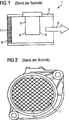
Die Erfindung betrifft einen Luftmassenmesser bestehend aus einem Rohr und einem in dem Rohr angebrachten Sensormodul zur Messung einer in dem Rohr mit einer Strömungsgeschwindigkeit in einer Hauptströmungsrichtung strömenden Gasmenge, wobei sich das Sensormodul im Rohr in Hauptströmungsrichtung ausdehnt, und ein Anfang des Sensormoduls eine erste Ebene normal zur Hauptströmungsrichtung definiert, und ein Ende des Sensormoduls eine zweite Ebene normal zur Hauptströmungsrichtung definiert, und wobei das Sensormodul einen Strömungskanal aufweist, der einen Teil der im Rohr strömenden Gasmenge aufnimmt und über Messelemente leitet. Um einen Luftmassenmesser anzugeben, der kostengünstig herstellbar ist und eine genaue Messung eines Luftmassenstromes ermöglicht, sind im Rohr ausgedehnte Strömungsleitelemente angeordnet, die parallel zur Hauptströmungsrichtung ausgerichtet sind, so dass Stirnflächen der Strömungsleitelemente von der Gasmenge angeströmt werden und an Wandbereichen der Strömungselemente die Gasmenge vorbeiströmt, wobei die Wandbereiche der Strömungsleitelemente sich mindestens teilweise zwischen der ersten und der zweiten Ebene erstrecken, so dass die Strömungsleitelemente die Strömungsgeschwindigkeit der Gasmenge bei geringer Strömungsgeschwindigkeit im Rohr im Bereich des Sensormoduls relativ zur Strömungsgeschwindigkeit im Rohr erhöhen und bei hoher Strömungsgeschwindigkeit der Gasmenge im Rohr im Bereich des Sensormoduls relativ zur Strömungsgeschwindigkeit weniger stark erhöhen.The invention relates to an air mass meter consisting of a pipe and a sensor module mounted in the pipe for measuring an amount of gas flowing in the pipe at a flow velocity in a main flow direction, the sensor module expanding in the pipe in the main flow direction, and a beginning of the sensor module a first plane normal defined to the main flow direction, and one end of the sensor module defines a second plane normal to the main flow direction, and wherein the sensor module has a flow channel that receives part of the gas flowing in the pipe and guides it via measuring elements. In order to provide an air mass meter that can be manufactured inexpensively and enables an exact measurement of an air mass flow, extensive flow guide elements are arranged in the pipe, which are aligned parallel to the main flow direction, so that the end faces of the flow guide elements are approached by the gas volume and the gas volume flows past wall areas of the flow elements wherein the wall areas of the flow guide elements extend at least partially between the first and the second level, so that the flow guide elements increase the flow rate of the amount of gas at a low flow rate in the pipe in the area of the sensor module relative to the flow rate in the pipe and at a high flow rate the amount of gas in the pipe in the area of the sensor module relative to the flow velocity.
Description
Die Erfindung betrifft einen Luftmassenmesser bestehend aus einem Rohr und einem in dem Rohr angebrachten Sensormodul zur Messung einer in dem Rohr mit einer Strömungsgeschwindigkeit in einer Hauptströmungsrichtung strömenden Gasmenge, wobei sich das Sensormodul im Rohr in Hauptströmungsrichtung ausdehnt, und ein Anfang des Sensormoduls eine erste Ebene normal zur Hauptströmungsrichtung definiert, und ein Ende des Sensormoduls eine zweite Ebene normal zur Hauptströmungsrichtung definiert, und wobei das Sensormodul einen Strömungskanal aufweist, der einen Teil der im Rohr strömenden Gasmenge aufnimmt und über Messelemente leitet.The invention relates to an air mass meter consisting of a pipe and a sensor module mounted in the pipe for measuring a gas flowing in the pipe at a flow velocity in a main flow direction, the sensor module expanding in the pipe in the main flow direction, and a beginning of the sensor module normalizing a first plane to the main flow direction, and one end of the sensor module defines a second plane normal to the main flow direction, and wherein the sensor module has a flow channel that receives and directs a portion of the gas flowing in the tube through sensing elements.
Der Begriff Luft wird im Kontext dieser Anmeldung als Beispiel für ein Gas oder Gasgemisch, dessen Massenstrom bestimmt werden kann, genutzt. Grundsätzlich kann mit dem erfindungsgemäßen Luftmassenmesser der Massenstrom eines jeden Gases oder Gasgemisches bestimmt werden.The term air is used in the context of this application as an example of a gas or gas mixture whose mass flow can be determined. In principle, the mass flow of each gas or gas mixture can be determined with the air mass meter according to the invention.
Derartige Luftmassenmesser sind bekannt, und sie werden in großer Zahl zum Beispiel im Automobilbau eingesetzt, um die zu einer Brennkraftmaschine strömende Luftmasse zu erfassen. Abhängig von dem durch den Luftmassenmesser erfassten Luftmassenstrom können sowohl Diagnosen, beispielsweise des Betriebs der Brennkraftmaschine, durchgeführt werden, als auch eine Steuerung der Brennkraftmaschine erfolgen. Zu diesen Zwecken ist ein auch unter unterschiedlichen Betriebsbedingungen zuverlässiges und möglichst präzises Erfassen des tatsächlichen Luftmassenstroms wichtig.Such air mass meters are known, and they are used in large numbers, for example in the automotive industry, to detect the air mass flowing to an internal combustion engine. Depending on the air mass flow detected by the air mass meter, both diagnoses, for example of the operation of the internal combustion engine, can be carried out, as well as control of the internal combustion engine. For these purposes, a reliable and precise as possible detection of the actual air mass flow is important under different operating conditions.
Aus der
Es ist Aufgabe der vorliegenden Erfindung, einen Luftmassenmesser anzugeben, der kostengünstig herstellbar ist und eine genaue Messung eines Luftmassenstromes ermöglicht.It is an object of the present invention to provide an air mass meter, which is inexpensive to produce and allows accurate measurement of air mass flow.
Diese Aufgabe wird durch die Merkmale des unabhängigen Patentanspruches gelöst.This object is solved by the features of the independent claim.
Dadurch, dass im Rohr ausgedehnte Strömungsleitelemente angeordnet sind, die parallel zur Hauptströmungsrichtung ausgerichtet sind, so dass Stirnflächen der Strömungsleitelemente von der Gasmenge angeströmt werden und an Wandbereichen der Strömungselemente die Gasmenge vorbeiströmt, wobei die Wandbereiche der Strömungsleitelemente sich mindestens teilweise zwischen der ersten und der zweiten Ebene erstrecken, so dass die Strömungsleitelemente die Strömungsgeschwindigkeit der Gasmenge bei geringer Strömungsgeschwindigkeit im Rohr im Bereich des Sensormoduls relativ zur Strömungsgeschwindigkeit im Rohr erhöhen und bei hoher Strömungsgeschwindigkeit der Gasmenge im Rohr im Bereich des Sensormoduls relativ zur Strömungsgeschwindigkeit weniger stark erhöhen, wird eine sehr genaue Messung der im den Rohr strömenden Luftmasse erreicht.Characterized in that in the tube extended flow guide elements are arranged, which are aligned parallel to the main flow direction, so that end faces of the flow are flowed by the amount of gas and flow past the gas flow on wall portions of the flow elements, wherein the wall portions of the flow guide at least partially between the first and the second Extend level, so that the flow guide increase the flow rate of gas flow at low flow velocity in the pipe in the region of the sensor module relative to the flow velocity in the pipe and at high flow rate of gas in the tube in the region of the sensor module relative to the flow rate increase less strongly, is a very accurate measurement reaches the air mass flowing in the pipe.
Bei einer Weiterbildung sind die Strömungsleitelemente aerodynamisch ausgebildet, was eine Störung der Luftströmung durch Verwirbelungen unterdrückt und eine präzise Messung gewährleistet. Auch die Ausbildung der Strömungsleitelemente in Tropfen- oder Flügelform führt zu diesen Vorteilen.In a further development, the flow guide elements are aerodynamically formed, which suppresses a disturbance of the air flow by turbulence and ensures a precise measurement. The formation of the flow guide in drop or wing shape leads to these advantages.
Bei einer nächsten Weiterbildung der Erfindung verringern die Strömungsleitelemente den Rohrquerschnitt um 10–50%. Dies führt zu einer Druckerhöhung an dem Sensormodul, wodurch die Messung des Luftmassenstroms sehr stabil und genau ausgeführt werden kann.In a next development of the invention, the flow guide elements reduce the pipe cross section by 10-50%. This leads to an increase in pressure at the sensor module, whereby the measurement of the air mass flow can be made very stable and accurate.
Bei einer Ausgestaltung sind das Rohr und die Strömungsleitelemente als einstückiges Bauteil ausgebildet. Dies führt zu einem sehr kostengünstigen, robusten und langlebigen Luftmassenmesser.In one embodiment, the tube and the flow guide elements are formed as a one-piece component. This results in a very low cost, rugged and durable air mass meter.
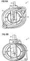
Die Erfindung wird nachfolgend anhand der
Dieses Gitter
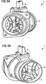
Die erfindungsgemäßen Luftmassensensoren, die in den
Eine zweite Ebene normal zur Hauptströmungsrichtung
In
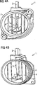
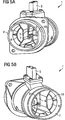
Auch in
In
BezugszeichenlisteLIST OF REFERENCE NUMBERS
- 11
- LuftmassenmesserAir flow sensor
- 22
- Rohrpipe
- 33
- Sensormodulsensor module
- 44
- HauptströmungsrichtungMain flow direction
- 55
- AnfangBeginning
- 66
- EndeThe End
- 77
- Strömungskanalflow channel
- 88th
- Strömungsleitelementeflow guide
- 99
- Stirnflächeface
- 1010
- Wandbereichwall area
- 1111
- Gittergrid
ZITATE ENTHALTEN IN DER BESCHREIBUNG QUOTES INCLUDE IN THE DESCRIPTION
Diese Liste der vom Anmelder aufgeführten Dokumente wurde automatisiert erzeugt und ist ausschließlich zur besseren Information des Lesers aufgenommen. Die Liste ist nicht Bestandteil der deutschen Patent- bzw. Gebrauchsmusteranmeldung. Das DPMA übernimmt keinerlei Haftung für etwaige Fehler oder Auslassungen.This list of the documents listed by the applicant has been generated automatically and is included solely for the better information of the reader. The list is not part of the German patent or utility model application. The DPMA assumes no liability for any errors or omissions.
Zitierte PatentliteraturCited patent literature
- EP 0458998 A1 [0004] EP 0458998 A1 [0004]
Claims (6)
Priority Applications (7)
| Application Number | Priority Date | Filing Date | Title |
|---|---|---|---|
| DE102010015523A DE102010015523A1 (en) | 2010-04-16 | 2010-04-16 | Air flow sensor |
| EP11713796A EP2558825A1 (en) | 2010-04-16 | 2011-04-12 | Air mass flowmeter |
| US13/641,439 US8950272B2 (en) | 2010-04-16 | 2011-04-12 | Air mass flowmeter |
| PCT/EP2011/055656 WO2011128310A1 (en) | 2010-04-16 | 2011-04-12 | Air mass flowmeter |
| CN201180018879.7A CN102844645B (en) | 2010-04-16 | 2011-04-12 | Air flow meter |
| KR1020127029909A KR20130092980A (en) | 2010-04-16 | 2011-04-12 | Air mass flowmeter |
| JP2013504232A JP2013525755A (en) | 2010-04-16 | 2011-04-12 | Air flow meter |
Applications Claiming Priority (1)
| Application Number | Priority Date | Filing Date | Title |
|---|---|---|---|
| DE102010015523A DE102010015523A1 (en) | 2010-04-16 | 2010-04-16 | Air flow sensor |
Publications (1)
| Publication Number | Publication Date |
|---|---|
| DE102010015523A1 true DE102010015523A1 (en) | 2011-10-20 |
Family
ID=44170442
Family Applications (1)
| Application Number | Title | Priority Date | Filing Date |
|---|---|---|---|
| DE102010015523A Ceased DE102010015523A1 (en) | 2010-04-16 | 2010-04-16 | Air flow sensor |
Country Status (7)
| Country | Link |
|---|---|
| US (1) | US8950272B2 (en) |
| EP (1) | EP2558825A1 (en) |
| JP (1) | JP2013525755A (en) |
| KR (1) | KR20130092980A (en) |
| CN (1) | CN102844645B (en) |
| DE (1) | DE102010015523A1 (en) |
| WO (1) | WO2011128310A1 (en) |
Cited By (4)
| Publication number | Priority date | Publication date | Assignee | Title |
|---|---|---|---|---|
| DE102011056127B3 (en) * | 2011-12-07 | 2013-04-18 | Pierburg Gmbh | Device for determining gas mass flow in exhaust gas channel of internal combustion engine, has mass flow sensor whose sensing elements are arranged in honeycomb-shaped lattice portion |
| EP2733343A1 (en) * | 2012-11-19 | 2014-05-21 | Toyota Boshoku Kabushiki Kaisha | Intake pipe structure for internal combustion engine |
| ES2534704R1 (en) * | 2013-01-11 | 2015-05-12 | Robert Bosch Gmbh | Detection device for the flow measurement of a fluid medium |
| DE102018217779A1 (en) | 2018-10-17 | 2020-04-23 | Continental Automotive Gmbh | Air mass measuring device with flow guiding element |
Families Citing this family (12)
| Publication number | Priority date | Publication date | Assignee | Title |
|---|---|---|---|---|
| GB2541550B (en) | 2012-03-15 | 2017-06-21 | Fisher & Paykel Healthcare Ltd | Respiratory gas humidification system |
| AU2013253097B2 (en) | 2012-04-27 | 2018-11-08 | Fisher & Paykel Healthcare Limited | Usability features for respiratory humidification system |
| WO2015038013A1 (en) | 2013-09-13 | 2015-03-19 | Fisher And Paykel Healthcare Limited | Connections for humidifcation system |
| CN103644948A (en) * | 2013-11-16 | 2014-03-19 | 中山欧麦克仪器设备有限公司 | Air mass flow meter |
| US10449319B2 (en) | 2014-02-07 | 2019-10-22 | Fisher & Paykel Healthcare Limited | Respiratory humidification system |
| EP3607988A1 (en) * | 2014-06-03 | 2020-02-12 | Fisher & Paykel Healthcare Limited | Flow mixers for respiratory therapy systems |
| US10274195B2 (en) | 2016-08-31 | 2019-04-30 | Honeywell International Inc. | Air/gas admittance device for a combustion appliance |
| WO2018106126A1 (en) | 2016-12-07 | 2018-06-14 | Fisher And Paykel Healthcare Limited | Sensing arrangements for medical devices |
| CN111220224B (en) * | 2018-11-26 | 2021-07-13 | 苏州原位芯片科技有限责任公司 | MEMS flow sensor chip |
| USD902255S1 (en) * | 2019-07-31 | 2020-11-17 | PRL Motorsports LLC | Intake system |
| CN112857499A (en) * | 2021-04-06 | 2021-05-28 | 浙江双良汽车零部件有限公司 | Air flow meter |
| CN114136647B (en) * | 2021-10-20 | 2023-10-03 | 中国航发四川燃气涡轮研究院 | Supersonic high-temperature three-dimensional flow field measuring device |
Citations (7)
| Publication number | Priority date | Publication date | Assignee | Title |
|---|---|---|---|---|
| EP0458998A1 (en) | 1990-05-30 | 1991-12-04 | Siemens Aktiengesellschaft | Current convertor |
| DE19750594A1 (en) * | 1997-04-24 | 1998-10-29 | Mitsubishi Electric Corp | Thermal mass flowmeter, e.g. for vehicle IC engine |
| DE19748853A1 (en) * | 1997-05-28 | 1998-12-03 | Mitsubishi Electric Corp | Heat-sensitive air mass-flow sensor for air intake to IC engine |
| DE10145195A1 (en) * | 2001-09-13 | 2003-04-10 | Siemens Ag | Arrangement for measuring air mass in induction channel of internal combustion engine has flow rectifier arranged at essentially same height or downstream of air mass sensor |
| DE10337824A1 (en) * | 2003-08-18 | 2005-03-24 | Siemens Ag | Combustion engine air inlet mass flow sensor has horizontal guide plate in recirculation area to guarantee definite sensor flow in pulse back flow |
| DE102004028214A1 (en) * | 2004-06-09 | 2005-12-29 | Robert Bosch Gmbh | Flow measurement device, for measuring pressure, temperature or flow velocity in gas flow, has one or more sensors with upstream flow guidance plates that incorporate turbulence generators on their leading edges |
| DE102007026673A1 (en) * | 2007-06-08 | 2008-12-18 | Robert Bosch Gmbh | Device for regulating parameter of flowing medium in line in mainstream direction, particularly determination of air mass stream in sucking in tract of internal-combustion engine, has line part visual art of line passage |
Family Cites Families (4)
| Publication number | Priority date | Publication date | Assignee | Title |
|---|---|---|---|---|
| DE4340882A1 (en) | 1993-12-01 | 1995-06-08 | Bosch Gmbh Robert | Mass flowrate measuring device for i.c. engine air intake |
| US6701781B1 (en) * | 2000-11-22 | 2004-03-09 | Visteon Global Technologies, Inc. | Mass air flow sensor bypass housing |
| JP4177183B2 (en) | 2003-06-18 | 2008-11-05 | 株式会社日立製作所 | Thermal air flow meter |
| JP4752472B2 (en) | 2005-12-02 | 2011-08-17 | 株式会社デンソー | Air flow measurement device |
-
2010
- 2010-04-16 DE DE102010015523A patent/DE102010015523A1/en not_active Ceased
-
2011
- 2011-04-12 JP JP2013504232A patent/JP2013525755A/en not_active Ceased
- 2011-04-12 US US13/641,439 patent/US8950272B2/en not_active Expired - Fee Related
- 2011-04-12 WO PCT/EP2011/055656 patent/WO2011128310A1/en active Application Filing
- 2011-04-12 CN CN201180018879.7A patent/CN102844645B/en not_active Expired - Fee Related
- 2011-04-12 EP EP11713796A patent/EP2558825A1/en not_active Withdrawn
- 2011-04-12 KR KR1020127029909A patent/KR20130092980A/en not_active Application Discontinuation
Patent Citations (7)
| Publication number | Priority date | Publication date | Assignee | Title |
|---|---|---|---|---|
| EP0458998A1 (en) | 1990-05-30 | 1991-12-04 | Siemens Aktiengesellschaft | Current convertor |
| DE19750594A1 (en) * | 1997-04-24 | 1998-10-29 | Mitsubishi Electric Corp | Thermal mass flowmeter, e.g. for vehicle IC engine |
| DE19748853A1 (en) * | 1997-05-28 | 1998-12-03 | Mitsubishi Electric Corp | Heat-sensitive air mass-flow sensor for air intake to IC engine |
| DE10145195A1 (en) * | 2001-09-13 | 2003-04-10 | Siemens Ag | Arrangement for measuring air mass in induction channel of internal combustion engine has flow rectifier arranged at essentially same height or downstream of air mass sensor |
| DE10337824A1 (en) * | 2003-08-18 | 2005-03-24 | Siemens Ag | Combustion engine air inlet mass flow sensor has horizontal guide plate in recirculation area to guarantee definite sensor flow in pulse back flow |
| DE102004028214A1 (en) * | 2004-06-09 | 2005-12-29 | Robert Bosch Gmbh | Flow measurement device, for measuring pressure, temperature or flow velocity in gas flow, has one or more sensors with upstream flow guidance plates that incorporate turbulence generators on their leading edges |
| DE102007026673A1 (en) * | 2007-06-08 | 2008-12-18 | Robert Bosch Gmbh | Device for regulating parameter of flowing medium in line in mainstream direction, particularly determination of air mass stream in sucking in tract of internal-combustion engine, has line part visual art of line passage |
Cited By (5)
| Publication number | Priority date | Publication date | Assignee | Title |
|---|---|---|---|---|
| DE102011056127B3 (en) * | 2011-12-07 | 2013-04-18 | Pierburg Gmbh | Device for determining gas mass flow in exhaust gas channel of internal combustion engine, has mass flow sensor whose sensing elements are arranged in honeycomb-shaped lattice portion |
| EP2733343A1 (en) * | 2012-11-19 | 2014-05-21 | Toyota Boshoku Kabushiki Kaisha | Intake pipe structure for internal combustion engine |
| US9212637B2 (en) | 2012-11-19 | 2015-12-15 | Toyota Boshoku Kabushiki Kaisha | Intake pipe structure for internal combustion engine |
| ES2534704R1 (en) * | 2013-01-11 | 2015-05-12 | Robert Bosch Gmbh | Detection device for the flow measurement of a fluid medium |
| DE102018217779A1 (en) | 2018-10-17 | 2020-04-23 | Continental Automotive Gmbh | Air mass measuring device with flow guiding element |
Also Published As
| Publication number | Publication date |
|---|---|
| EP2558825A1 (en) | 2013-02-20 |
| CN102844645B (en) | 2016-05-25 |
| KR20130092980A (en) | 2013-08-21 |
| US20130025353A1 (en) | 2013-01-31 |
| WO2011128310A1 (en) | 2011-10-20 |
| US8950272B2 (en) | 2015-02-10 |
| JP2013525755A (en) | 2013-06-20 |
| CN102844645A (en) | 2012-12-26 |
Similar Documents
| Publication | Publication Date | Title |
|---|---|---|
| DE102010015523A1 (en) | Air flow sensor | |
| DE3044152C2 (en) | Air flow meter | |
| DE102005026709A1 (en) | flow sensor | |
| DE102008042807B4 (en) | Device for determining a parameter of a flowing fluid medium | |
| EP1818665A2 (en) | Particle sensor | |
| DE19942501A1 (en) | Device for measuring at least one parameter of a medium flowing in a line | |
| DE102008049843A1 (en) | Air mass sensor for determining flow rate of medium, particularly air flowing in inlet port of internal-combustion engine, has housing body, which has flow channel and bypass formed in housing body | |
| DE102007044079B4 (en) | Flow Sensor | |
| DE202011105809U1 (en) | Device for measuring the mass flow of a gas | |
| EP3769052B1 (en) | Sensor assembly | |
| DE102007023163B4 (en) | Flow meter | |
| DE102008032309B4 (en) | Sensor arrangement for measuring the state of a liquid, in particular of oil | |
| DE102005046215B4 (en) | Device for determining mass flows on a radiator | |
| DE102018217779A1 (en) | Air mass measuring device with flow guiding element | |
| DE102017205838A1 (en) | Sensor element for detecting at least one property of a fluid medium | |
| DE10027830B4 (en) | Mass flow meter | |
| DE102012211126A1 (en) | Sensor arrangement for determining flow property of fluid medium e.g. intake air of combustion engine, has lattice struts which are arranged such that at each connection point, the maximum of three lattice elements are interconnected | |
| DE102017117389A1 (en) | Flowmeter | |
| DE102004008930A1 (en) | Air flow measurement device for a combustion engine is arranged in a bypass to a main gas carrying pipe, which is routed outside the main pipe, so that the measurement device can be easily accessed | |
| DE102007027252A1 (en) | Gaseous media's mass flow rate determining device for motor vehicle, has sensors formed so that openings are positioned at same position between front side of radiator and/or channels inlet side and rear side and/or channels outlet side | |
| AT519854B1 (en) | Flow Sensor | |
| EP3610227A1 (en) | Sensor element for detecting at least oneproperty of a fluid medium | |
| DE102014019641A1 (en) | Exhaust system for an internal combustion engine | |
| DE102017129446A1 (en) | Device for determining a total pressure loss of a radiator of a motor vehicle | |
| AT518663B1 (en) | Device for determining the injection rate variance of gas valves, in particular for internal combustion engines operable with gaseous fuels |
Legal Events
| Date | Code | Title | Description |
|---|---|---|---|
| R016 | Response to examination communication | ||
| R002 | Refusal decision in examination/registration proceedings | ||
| R003 | Refusal decision now final |