DE102005028268B4 - Method and apparatus for generating and detecting a Raman spectrum - Google Patents
Method and apparatus for generating and detecting a Raman spectrum Download PDFInfo
- Publication number
- DE102005028268B4 DE102005028268B4 DE102005028268A DE102005028268A DE102005028268B4 DE 102005028268 B4 DE102005028268 B4 DE 102005028268B4 DE 102005028268 A DE102005028268 A DE 102005028268A DE 102005028268 A DE102005028268 A DE 102005028268A DE 102005028268 B4 DE102005028268 B4 DE 102005028268B4
- Authority
- DE
- Germany
- Prior art keywords
- laser diode
- medium
- examined
- excitation
- radiation
- Prior art date
- Legal status (The legal status is an assumption and is not a legal conclusion. Google has not performed a legal analysis and makes no representation as to the accuracy of the status listed.)
- Expired - Fee Related
Links
- 238000001237 Raman spectrum Methods 0.000 title claims abstract description 39
- 238000000034 method Methods 0.000 title claims abstract description 35
- 230000005284 excitation Effects 0.000 claims abstract description 63
- 230000005855 radiation Effects 0.000 claims abstract description 34
- 230000008878 coupling Effects 0.000 claims abstract description 16
- 238000010168 coupling process Methods 0.000 claims abstract description 16
- 238000005859 coupling reaction Methods 0.000 claims abstract description 16
- 230000005670 electromagnetic radiation Effects 0.000 claims abstract description 3
- 238000010183 spectrum analysis Methods 0.000 claims abstract description 3
- 230000003287 optical effect Effects 0.000 claims description 22
- 230000003595 spectral effect Effects 0.000 claims description 19
- 238000001069 Raman spectroscopy Methods 0.000 claims description 18
- 238000012545 processing Methods 0.000 claims description 14
- 238000001514 detection method Methods 0.000 claims description 8
- 239000013307 optical fiber Substances 0.000 claims description 5
- BJQHLKABXJIVAM-UHFFFAOYSA-N bis(2-ethylhexyl) phthalate Chemical compound CCCCC(CC)COC(=O)C1=CC=CC=C1C(=O)OCC(CC)CCCC BJQHLKABXJIVAM-UHFFFAOYSA-N 0.000 claims description 3
- 230000004913 activation Effects 0.000 claims description 2
- 230000001360 synchronised effect Effects 0.000 claims 2
- 238000000926 separation method Methods 0.000 claims 1
- 238000001228 spectrum Methods 0.000 description 15
- 230000035945 sensitivity Effects 0.000 description 7
- YNPNZTXNASCQKK-UHFFFAOYSA-N phenanthrene Chemical compound C1=CC=C2C3=CC=CC=C3C=CC2=C1 YNPNZTXNASCQKK-UHFFFAOYSA-N 0.000 description 4
- 230000001629 suppression Effects 0.000 description 4
- 230000000694 effects Effects 0.000 description 3
- 230000002452 interceptive effect Effects 0.000 description 3
- 238000005259 measurement Methods 0.000 description 3
- 239000000523 sample Substances 0.000 description 3
- 238000003705 background correction Methods 0.000 description 2
- 230000008030 elimination Effects 0.000 description 2
- 238000003379 elimination reaction Methods 0.000 description 2
- 230000000737 periodic effect Effects 0.000 description 2
- 230000008569 process Effects 0.000 description 2
- 238000004458 analytical method Methods 0.000 description 1
- 230000008901 benefit Effects 0.000 description 1
- 239000012472 biological sample Substances 0.000 description 1
- 238000004364 calculation method Methods 0.000 description 1
- 230000008859 change Effects 0.000 description 1
- 238000003889 chemical engineering Methods 0.000 description 1
- 238000007796 conventional method Methods 0.000 description 1
- 238000012937 correction Methods 0.000 description 1
- 230000007423 decrease Effects 0.000 description 1
- 238000011161 development Methods 0.000 description 1
- 238000005516 engineering process Methods 0.000 description 1
- 230000007613 environmental effect Effects 0.000 description 1
- 238000002189 fluorescence spectrum Methods 0.000 description 1
- 239000000463 material Substances 0.000 description 1
- 238000012544 monitoring process Methods 0.000 description 1
- 239000004065 semiconductor Substances 0.000 description 1
- 238000004611 spectroscopical analysis Methods 0.000 description 1
Images

Classifications
-
- G—PHYSICS
- G01—MEASURING; TESTING
- G01N—INVESTIGATING OR ANALYSING MATERIALS BY DETERMINING THEIR CHEMICAL OR PHYSICAL PROPERTIES
- G01N21/00—Investigating or analysing materials by the use of optical means, i.e. using sub-millimetre waves, infrared, visible or ultraviolet light
- G01N21/62—Systems in which the material investigated is excited whereby it emits light or causes a change in wavelength of the incident light
- G01N21/63—Systems in which the material investigated is excited whereby it emits light or causes a change in wavelength of the incident light optically excited
- G01N21/65—Raman scattering
-
- G—PHYSICS
- G01—MEASURING; TESTING
- G01J—MEASUREMENT OF INTENSITY, VELOCITY, SPECTRAL CONTENT, POLARISATION, PHASE OR PULSE CHARACTERISTICS OF INFRARED, VISIBLE OR ULTRAVIOLET LIGHT; COLORIMETRY; RADIATION PYROMETRY
- G01J3/00—Spectrometry; Spectrophotometry; Monochromators; Measuring colours
- G01J3/02—Details
- G01J3/10—Arrangements of light sources specially adapted for spectrometry or colorimetry
-
- G—PHYSICS
- G01—MEASURING; TESTING
- G01J—MEASUREMENT OF INTENSITY, VELOCITY, SPECTRAL CONTENT, POLARISATION, PHASE OR PULSE CHARACTERISTICS OF INFRARED, VISIBLE OR ULTRAVIOLET LIGHT; COLORIMETRY; RADIATION PYROMETRY
- G01J3/00—Spectrometry; Spectrophotometry; Monochromators; Measuring colours
- G01J3/28—Investigating the spectrum
- G01J3/44—Raman spectrometry; Scattering spectrometry ; Fluorescence spectrometry
- G01J2003/4424—Fluorescence correction for Raman spectrometry
-
- G—PHYSICS
- G01—MEASURING; TESTING
- G01N—INVESTIGATING OR ANALYSING MATERIALS BY DETERMINING THEIR CHEMICAL OR PHYSICAL PROPERTIES
- G01N21/00—Investigating or analysing materials by the use of optical means, i.e. using sub-millimetre waves, infrared, visible or ultraviolet light
- G01N21/62—Systems in which the material investigated is excited whereby it emits light or causes a change in wavelength of the incident light
- G01N21/63—Systems in which the material investigated is excited whereby it emits light or causes a change in wavelength of the incident light optically excited
- G01N21/65—Raman scattering
- G01N2021/653—Coherent methods [CARS]
- G01N2021/656—Raman microprobe
Abstract
Verfahren zur Erzeugung und zur Detektion eines Raman-Spektrums (20) eines zu untersuchenden Mediums (8) mit folgenden Verfahrensschritten: – Erzeugung elektromagnetischer Anregungsstrahlung mittels einer Laserdiode (1), – Einkoppeln der Anregungsstrahlung in das zu untersuchende Medium (8), – Einkoppeln der vom zu untersuchenden Medium (8) gestreuten elektromagnetischen Strahlung in ein spektral-optisches System (10) zur spektralen Analyse der gestreuten Strahlung, wobei die eine Laserdiode (1) zur Erzeugung von Anregungsstrahlung mindestens zweier unterschiedlicher Wellenlängen (λ1, λ2) mit mindestens zwei unterschiedlichen Anregungsbedingungen angesteuert wird und aus der gestreuten Strahlung für die unterschiedlichen Anregungswellenlängen (λ1, λ2) jeweils mindestens ein Raman-Spektrum (16, 17) detektiert wird und aus den mindestens zwei detektierten Raman-Spektren (16, 17) das Raman-Spektrum (20) des zu untersuchenden Mediums (8) ermittelt wird, dadurch gekennzeichnet, dass die zwei unterschiedlichen Anregungsbedingungen für die Laserdiode (1) durch den an die Laserdiode (1) angelegten elektrischen Strom eingestellt werden und die Laserdiode (1) mit einem internen frequenzselektiven Element verwendet wird.Method for generating and detecting a Raman spectrum (20) of a medium (8) to be examined with the following method steps: - generating electromagnetic excitation radiation by means of a laser diode (1), - coupling the excitation radiation into the medium to be examined (8), - coupling the electromagnetic radiation scattered by the medium to be examined (8) into a spectral-optical system (10) for the spectral analysis of the scattered radiation, wherein the one laser diode (1) for generating excitation radiation at least two different wavelengths (λ1, λ2) with at least two At least one Raman spectrum (16, 17) is detected from the scattered radiation for the different excitation wavelengths (λ1, λ2) and from the at least two detected Raman spectra (16, 17) the Raman spectrum ( 20) of the medium to be examined (8) is determined, characterized in that the two different excitation conditions for the laser diode (1) are adjusted by the electric current applied to the laser diode (1) and the laser diode (1) is used with an internal frequency-selective element.
Description
Die Erfindung betrifft ein Verfahren und eine Vorrichtung mit den in den Oberbegriffen der Ansprüche 1 (Verfahren) und 19 (Vorrichtung) genannten Merkmalen.The invention relates to a method and a device having the features mentioned in the preambles of claims 1 (method) and 19 (device).
Die Raman-Spektroskopie hat sich in der letzten Zeit, nicht zuletzt auf Grund der Entwicklung von kostengünstigeren Halbleiterlasern, zu einer etablierten Methode in den Materialwissenschaften, der chemischen Verfahrenstechnik, der Pharmazie, der Umwelttechnik, der Analytik und in der Prozessüberwachung entwickelt. In vielen Anwendungsfällen kommen dabei Sonden zum Einsatz, die in der Regel mit einem Spektrometer gekoppelt werden.Raman spectroscopy has recently become an established method in materials science, chemical engineering, pharmacy, environmental technology, analytics, and process monitoring, not least due to the development of lower cost semiconductor lasers. In many applications, probes are used that are usually coupled with a spectrometer.
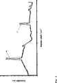
Die Anwendung der Raman-Spektroskopie in den oben genannten Gebieten wird regelmäßig dadurch eingeschränkt, dass neben den gewünschten Raman-Signalen häufig auch ein Fluoreszenzhintergrund oder eine breitbandige Untergrundstreuung angeregt wird. Insbesondere bei der Anregung des Raman-Effekts im sichtbaren Spektralbereich neigen vor allem biologische Proben zur Fluoreszenz, wodurch die Raman-Spektren völlig verdeckt werden können. Zwar tritt bei einer Anregung des Raman-Effekts mit Strahlung im nahen Infrarotbereich praktisch keine Fluoreszenzanregung mehr auf, jedoch verringert sich die Intensität der Raman-Streustrahlung mit der vierten Potenz der absoluten Wellenzahl, so dass das spektral-optische System eine deutlich größere Empfindlichkeit aufweisen muss, was mit einem hohen apparativen Aufwand einhergeht. Ein weiteres Problem besteht darin, dass bei der Verwendung von CCD-Detektoren vordergründig eine charakteristische Struktur der Baseline, das so genannte Fixed Pattern auftritt. Das Fixed Pattern ist eine feststehende Störstruktur, welche die Bilder von CCD-Kameras oder CCD-Abtastern überlagert. Durch das Fixed Pattern werden die schwachen Raman-Signale (bei Verwendung von CCD-basierten Empfängern) maskiert und die erreichbare Empfindlichkeit begrenzt. Herkömmliche Verfahren korrigieren dies mit Dunkel- oder Leerspektren. Durch eine solche Korrektur kann das Fixed Pattern jedoch oft nicht ausreichend eliminiert werden, da in einem anderen Intensitätsbereich gemessen und dadurch die physikalische Natur des Fixed Pattern nicht ausreichend berücksichtigt wird.The application of Raman spectroscopy in the above-mentioned areas is regularly limited by the fact that in addition to the desired Raman signals often a fluorescence background or a broadband background scattering is excited. In particular, in the excitation of the Raman effect in the visible spectral region especially biological samples tend to fluorescence, whereby the Raman spectra can be completely obscured. Although virtually no fluorescence excitation occurs when the Raman effect is excited with radiation in the near infrared range, the intensity of the Raman scattering radiation decreases with the fourth power of the absolute wave number, so that the spectral optical system must have a significantly greater sensitivity , which is associated with a high expenditure on equipment. Another problem is that the use of CCD detectors superficially a characteristic structure of the baseline, the so-called fixed pattern occurs. The Fixed Pattern is a fixed interfering structure that overlays the images of CCD cameras or CCD scanners. The fixed pattern masks the weak Raman signals (when using CCD-based receivers) and limits the achievable sensitivity. Conventional methods correct this with dark or empty spectra. However, such a correction often does not sufficiently eliminate the fixed pattern since it is measured in a different intensity range and thus does not sufficiently take into account the physical nature of the fixed pattern.
Sowohl die Fluoreszenzunterdrückung als auch die Untergrundkorrektur sind in der Raman-Spektroskopie auf vielfältige Weise untersucht worden. Beispielsweise kann die Fluoreszenz durch schnelles Gating im Spektrum eliminiert werden, wobei ausgenutzt wird, dass die Fluoreszenz langsam im Vergleich zum Raman-Effekt ist. Dies erfordert jedoch aufwendige Versuchsanordnungen mit gepulsten Lasern, wie beispielsweise aus P. Matousek et al. „Fluorescence suppression in resonance Raman spectroscopy using a high-performance picosecond Kerr gate”, J. Raman Spectroscopy 2001, 32, 983–988 bekannt ist.Both fluorescence suppression and background correction have been investigated in a variety of ways in Raman spectroscopy. For example, the fluorescence can be eliminated by fast gating in the spectrum, making use of the fact that the fluorescence is slow compared to the Raman effect. However, this requires expensive experimental arrangements with pulsed lasers, as described, for example, by P. Matousek et al. "Fluorescence suppression in Raman spectroscopy using a high-performance picosecond Kerr gate", J. Raman Spectroscopy 2001, 32, 983-988.
Weiterhin ist es aus A. P. Shreve et al., Appl. Spectroscopy 1992, 46, 707 bekannt, dass durch die Verwendung zweier Laserwellenlängen, die gegeneinander verschoben sind, eine Untergrundkorrektur zur Beseitigung der Fluoreszenz möglich realisiert werden kann. Als Lichtquelle wird bei Shreve et al. ein Ti:Saphir Laser verwendet, der mit Hilfe eines diffraktiven Elements auf zwei Wellenlängen in der Frequenz verschoben wird. Ein Nachteil dieser Anordnung ist vor allem im komplexen Aufbau zu sehen.Further, it is known from A.P. Shreve et al., Appl. Spectroscopy 1992, 46, 707 known that by the use of two laser wavelengths which are shifted from each other, a background correction to eliminate the fluorescence can be realized possible. The light source is described by Shreve et al. a Ti: sapphire laser is used, which is shifted by means of a diffractive element to two wavelengths in frequency. A disadvantage of this arrangement can be seen above all in the complex structure.
Die Aufgabe der vorliegenden Erfindung besteht darin, ein Verfahren und eine Vorrichtung zur Erzeugung und Detektion eines Raman-Spektrums eines zu untersuchenden Mediums anzugeben, mit welchen das Raman-Spektrum eines zu untersuchenden Mediums mit einer hohen Empfindlichkeit bei vergleichsweise geringem apparativen Aufwand ermittelt werden kann. Insbesondere soll die Verwendung mehrerer Anregungslichtquellen vermieden werden können.The object of the present invention is to provide a method and a device for generating and detecting a Raman spectrum of a medium to be examined, with which the Raman spectrum of a medium to be examined can be determined with a high sensitivity with relatively little expenditure on equipment. In particular, the use of multiple excitation light sources should be avoided.
Diese Aufgaben werden erfindungsgemäß gelöst durch die Merkmale der Ansprüche 1 (Verfahren) und 19 (Vorrichtung). Bevorzugte Ausgestaltungen der Erfindung sind in den Unteransprüchen enthalten.These objects are achieved according to the invention by the features of claims 1 (method) and 19 (device). Preferred embodiments of the invention are contained in the subclaims.
Das erfindungsgemäße Verfahren zur Erzeugung und zur Detektion eines Raman-Spektrums eines zu untersuchenden Mediums weist folgende Verfahrensschritte auf:
- – Erzeugung elektromagnetischer Anregungsstrahlung mittels einer Laserdiode,
- – Einkoppeln der Anregungsstrahlung in das zu untersuchende Medium,
- – Einkoppeln der vom zu untersuchenden Medium gestreuten elektromagnetischen Strahlung in ein spektral-optisches System zur spektralen Analyse der gestreuten Strahlung,
- Generation of electromagnetic excitation radiation by means of a laser diode,
- Coupling the excitation radiation into the medium to be examined,
- Coupling the electromagnetic radiation scattered by the medium to be examined into a spectral-optical system for the spectral analysis of the scattered radiation,
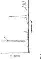
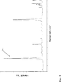
Ein besonderer Vorteil des erfindungsgemäßen Verfahrens besteht darin, dass lediglich eine Laserdiode verwendet wird, wobei es durch die (bevorzugt alternierende) Ansteuerung der Laserdiode mit unterschiedlichen Anregungsbedingungen (d. h. Ansteuerung der Laserdiode mit unterschiedlichen Stromstärken, unterschiedlichen optischen Pumpintensitäten und/oder unterschiedlichen Temperaturen des Resonators) möglich ist, dass die Laserdiode auf zwei unterschiedlichen Wellenlängen (bevorzugt alternierend) emittiert, so dass für diese zwei unterschiedlichen (Anregungs-)Wellenlängen jeweils ein Raman-Spektrum detektiert werden kann und aus den mindestens zwei erhaltenen Raman-Spektren ein Raman-Spektrum für das zu untersuchende Medium berechnet werden kann, wobei der Fluoreszenzanteil durch die Detektion von mindestens zwei frequenzverschobenen Raman-Spektren herausgerechnet werden kann. Weiterhin ist es möglich, bei Verwendung von CCD-Elementen im spektral-optischen System das Fixed Pattern und einen gerätespezifischen spektralen Untergrund (Filtercharakteristik) zu eliminieren. Hierdurch wird eine hohe Nachweisempfindlichkeit bei vergleichsweise geringem apparativen Aufwand erhalten, insbesondere ist lediglich eine Laserdiode als Anregungslichtquelle erforderlich. Dazu wird erfindungsgemäß eine Laserdiode mit internem frequenz-selektivem Element (vorzugsweise Gitter, Etalon oder Mach-Zehnder-Interferometer) verwendet.A particular advantage of the method according to the invention is that only one laser diode is used, it being possible by the (preferably alternating) control of the laser diode with different excitation conditions (ie activation of the laser diode with different current intensities, different optical pump intensities and / or different resonator temperatures). it is possible that the laser diode emits at two different wavelengths (preferably alternately), so that in each case one Raman spectrum can be detected for these two different (excitation) wavelengths and from the at least two Raman spectra obtained a Raman spectrum for the can be calculated to medium to be examined, wherein the fluorescence component can be excluded by the detection of at least two frequency-shifted Raman spectra. Furthermore, it is possible to eliminate the fixed pattern and a device-specific spectral background (filter characteristic) when using CCD elements in the spectral optical system. As a result, a high detection sensitivity is obtained with comparatively low outlay on equipment, in particular only one laser diode is required as the excitation light source. For this purpose, a laser diode with internal frequency-selective element (preferably grating, etalon or Mach-Zehnder interferometer) is used according to the invention.
Zur Eliminierung des Fixed Pattern ist es erforderlich, dass die zwei zur Anregung verwendeten Wellenlängen einen ausreichenden Wellenlängenabstand aufweisen. Grundsätzlich wäre zu erwarten, dass der notwendige Wellenlängenabstand bei Verwendung einer Laserdiode ohne externe Kavität nicht realisierbar ist. Darüber hinaus sind Laserdioden mit externer Kavität weniger kompakt. Es wurde jedoch gefunden, dass insbesondere bei Verwendung einer Laserdiode mit internem frequenz-selektiven Element ein zur Eliminierung des Fixed Pattern ausreichender Wellenlängenabstand (beispielsweise durch Ansteuerung der Laserdiode mit unterschiedlichen Stromstärken) erzielt werden kann.To eliminate the fixed pattern, it is necessary that the two wavelengths used for excitation have sufficient wavelength spacing. In principle, it would be expected that the necessary wavelength spacing would not be feasible when using a laser diode without an external cavity. In addition, laser diodes with external cavity are less compact. However, it has been found that, in particular when using a laser diode with internal frequency-selective element sufficient to eliminate the fixed pattern wavelength spacing (for example, by driving the laser diode with different currents) can be achieved.
Die Linienbreite (FWHM) der Laserdiode beträgt vorzugsweise kleiner 30 GHz, besonders bevorzugt kleiner 3 GHz, besonders bevorzugt kleiner 100 MHz, besonders bevorzugt kleiner 10 MHz.The line width (FWHM) of the laser diode is preferably less than 30 GHz, particularly preferably less than 3 GHz, particularly preferably less than 100 MHz, particularly preferably less than 10 MHz.
Durch die Verwendung einer schmalbandigen Laserdiode mit einem internen frequenz-selektiven Element wird es weiterhin möglich, auf eine regelmäßige Kalibrierung (d. h. vor oder während jeder Messung) der durch die von der (mit unterschiedlichen Anregungsbedingungen) angesteuerten Laserdiode emittierten Strahlung zu verzichten. Es ist lediglich notwendig, in großen Zeitabständen eine Wellenlängenkontrolle vorzunehmen. Dies reduziert den apparativen und zeitlichen Aufwand erheblich, wodurch ein Einsatz des erfindungsgemäßen Verfahrens auch mit konventionellen, preiswerten Geräten möglich wird. Eine Lichtquelle, die eine solche Echtzeit-Untergrundunterdrückung für die Raman-Spektroskopie ermöglicht, erforderte nach dem bisherigen Stand der Technik einen deutlich höheren apparativen Aufwand.The use of a narrow band laser diode with an internal frequency selective element also makes it possible to dispense with periodic calibration (i.e., before or during each measurement) of the radiation emitted by the laser diode driven by (with different excitation conditions). It is only necessary to perform a wavelength control at long intervals. This significantly reduces the expenditure on equipment and time, which makes it possible to use the method according to the invention also with conventional, inexpensive devices. A light source that allows such a real-time background suppression for Raman spectroscopy, required in the prior art, a much higher equipment cost.
Die verwendete Laserdiode ist vorzugsweise monolithisch und für einen vorgegebenen Wellenlängenbereich durchstimmbar schmalbandig ausgebildet.The laser diode used is preferably monolithic and tunable narrowband for a given wavelength range.
Vorzugsweise wird die Laserdiode mit einer Frequenz größer als 0,1 Hz zwischen den beiden Stromstärken (bzw. anderen Anregungsbedingungen) hin und her geschaltet. Alternativ ist auch eine nicht-periodische Anregung möglich. Voraussetzung ist lediglich, dass die Laserdiode innerhalb eines (vorzugsweise kleinen) Zeitintervalls mit mindestens zwei unterschiedlichen Anregungsbedingungen derart angesteuert wird, dass sie auf mindestens zwei Wellenlängen mit einem ausreichenden Wellenlängenabstand (vorzugsweise 0,5 nm) emittiert. Das Zeitintervall beträgt vorzugsweise 60 s, besonders bevorzugt 10 s, besonders bevorzugt 1 s, besonders bevorzugt 0,1 s und wird so gewählt. Als Detektor wird vorzugsweise eine CCD-Zeile verwendet. Als spektral-optisches System wird vorzugsweise ein Spektrograph mit CCD-Zeile verwendet. Weiterhin ist es vorgesehen, die Laserdiode mittels einer Anregungsquelle (bevorzugt Stromquelle) anzusteuern, wobei die Ausgangsleistung der Anregungsquelle moduliert wird. Zur Modulation der Anregungsquelle wird vorzugsweise ein Funktionsgenerator, besonders bevorzugt ein Rechteckgenerator verwendet. Es ist weiterhin vorgesehen, das spektral-optische System mit einem Datenverarbeitungsgerät zur Auswertung der vom spektral-optischen System erhaltenen Messdaten zu verbinden. Um für die unterschiedlichen Anregungswellenlängen (welche vorzugsweise alternierend in das Medium eingekoppelt werden) auch die dazugehörigen Raman-Spektren zu detektieren, was zur Untergrundunterdrückung (Berechnung) notwendig ist, ist es erfindungsgemäß vorgesehen, nicht nur die Anregungsquelle zur Ansteuerung der Laserdiode, sondern auch das spektral-optische System bzw. das mit dem spektral-optischen System verbundene Datenverarbeitungsgerät zu toren. Hierzu sind neben der Anregungsquelle auch das spektral-optische System und das Datenverarbeitungsgerät mit dem Mittel zur Ansteuerung der Laserdiode (Modulator) verbunden.Preferably, the laser diode with a frequency greater than 0.1 Hz between the two currents (or other excitation conditions) switched back and forth. Alternatively, a non-periodic excitation is possible. The only prerequisite is that the laser diode within a (preferably small) time interval with at least two different excitation conditions is controlled such that it emits at least two wavelengths with a sufficient wavelength spacing (preferably 0.5 nm). The time interval is preferably 60 s, particularly preferably 10 s, particularly preferably 1 s, particularly preferably 0.1 s, and is chosen in this way. As a detector, a CCD line is preferably used. As a spectral-optical system, a spectrograph with CCD line is preferably used. Furthermore, it is provided to drive the laser diode by means of an excitation source (preferably current source), wherein the output power of the excitation source is modulated. To modulate the excitation source, a function generator, more preferably a rectangular generator, is preferably used. It is further provided to connect the spectral optical system with a data processing device for evaluating the measurement data obtained from the spectral optical system. In order to detect the associated Raman spectra for the different excitation wavelengths (which are preferably coupled in alternately into the medium), which is necessary for background suppression (calculation), it is in accordance with the invention provided, not only the excitation source for driving the laser diode, but also the spectral optical system or the data processing device connected to the spectral optical system. For this purpose, in addition to the excitation source and the spectral optical system and the data processing device with the means for driving the laser diode (modulator) are connected.
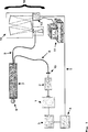
Die Vorrichtung zur Erzeugung und zur Detektion eines Raman-Spektrums weist erfindungsgemäß eine Anregungslichtquelle, ein spektral-optisches System und ein Datenverarbeitungsgerät auf, wobei das spektral-optische System mit dem Datenverarbeitungsgerät verbunden ist, wobei die Vorrichtung weiterhin Mittel zur Einkopplung der Anregungsstrahlung in das zu untersuchende Medium und Mittel zur Einkopplung der vom zu untersuchenden Medium gestreuten Strahlung in das spektral-optische System aufweist, wobei die Anregungslichtquelle eine Laserdiode mit einem internen frequenz-selektiven Element ist, wobei die Laserdiode zur Erzeugung unterschiedlicher Anregungswellenlängen über einen Modulator mit einer Stromquelle verbunden ist, wobei das spektral-optische System und/oder das Datenverarbeitungsgerät mit dem Modulator verbunden ist. Hierdurch kann die Laserdiode sehr schmalbandig auf zwei Wellenlängen (vorzugsweise alternierend, entsprechend der Ansteuerung) emittieren, ohne dass es einer vorherigen Kalibrierung der einzelnen Wellenlängen bzw. der Laserdiode bedarf. Mit der erfindungsgemäßen Vorrichtung können Raman-Spektren mit hoher Empfindlichkeit (bei Eliminierung von Fixed Pattern und Fluoreszenzanteil) ermittelt werden, wobei die erfindungsgemäße Vorrichtung einen vergleichsweise einfachen Aufbau (lediglich eine Anregungslichtquelle, keine externe Kavität) aufweist.The device for generating and detecting a Raman spectrum according to the invention comprises an excitation light source, a spectral optical system and a data processing device, wherein the spectral optical system is connected to the data processing device, wherein the device further comprises means for coupling the excitation radiation in the having investigating medium and means for coupling the scattered radiation from the medium to be examined in the spectral optical system, wherein the excitation light source is a laser diode having an internal frequency-selective element, wherein the laser diode is connected to generate different excitation wavelengths via a modulator to a power source , wherein the spectral optical system and / or the data processing device is connected to the modulator. As a result, the laser diode can emit very narrowband at two wavelengths (preferably alternating, in accordance with the drive), without requiring a prior calibration of the individual wavelengths or of the laser diode. With the device according to the invention Raman spectra can be determined with high sensitivity (with elimination of fixed pattern and fluorescence component), wherein the device according to the invention has a comparatively simple structure (only one excitation light source, no external cavity).
Erfindungsgemäß weist das Mittel zur Ansteuerung der Laserdiode eine mit einem Modulator verbundene Stromquelle auf. Alternativ weist das Mittel zur Ansteuerung der Laserdiode ein Mittel zur Steuerung der Intensität der optischen Anregung des aktiven Mediums der Laserdiode oder ein Mittel zur Steuerung der Temperatur des Resonators der Laserdiode auf. Vorzugsweise weist die erfindungsgemäße Vorrichtung zusätzlich optische Filter, beispielsweise zur Eliminierung der Rayleigh-Linie auf.According to the invention, the means for driving the laser diode comprises a current source connected to a modulator. Alternatively, the means for driving the laser diode comprises means for controlling the intensity of the optical excitation of the active medium of the laser diode or a means for controlling the temperature of the resonator of the laser diode. Preferably, the device according to the invention additionally comprises optical filters, for example for the elimination of the Rayleigh line.
Erfindungsgemäß ist das spektral-optische System oder das Datenverarbeitungsgerät mit dem Mittel zur Ansteuerung der Laserdiode (Modulator) verbunden, da hierdurch die Anregung mit unterschiedlichen Wellenlängen und die Detektion des gestreuten Licht synchron erfolgen können. Hierdurch lassen sich beispielsweise schnell ändernde Prozesse zeitaufgelöst überwachen. Hierzu kann die Laserdiode bzgl. ihrer Anregungsbedingungen auch mit deutlich höheren Frequenzen, beispielsweise größer 10 Hz angesteuert werden.According to the invention, the spectral-optical system or the data processing device is connected to the means for driving the laser diode (modulator), since in this way the excitation with different wavelengths and the detection of the scattered light can take place synchronously. As a result, processes that change quickly, for example, can be monitored in a time-resolved manner. With regard to their excitation conditions, the laser diode can also be driven at significantly higher frequencies, for example greater than 10 Hz.
Der Modulator ist vorzugsweise ein Funktionsgenerator, besonders bevorzugt ein Rechteckgenerator. Das Mittel zur Einkopplung der Anregungsstrahlung in das zu untersuchende Medium und das Mittel zur Einkopplung der vom zu untersuchenden Medium rückgestreuten Strahlung in das spektral-optisches System weist vorzugsweise eine optische Faser auf.The modulator is preferably a function generator, particularly preferably a square-wave generator. The means for coupling the excitation radiation into the medium to be examined and the means for coupling the backscattered radiation from the medium to be examined into the spectral-optical system preferably has an optical fiber.
Die Erfindung wird nachstehend anhand eines Ausführungsbeispiels näher erläutert. Es zeigen:The invention will be explained in more detail below with reference to an embodiment. Show it:
Hierdurch emittiert die Laserdiode
Claims (24)
Priority Applications (5)
| Application Number | Priority Date | Filing Date | Title |
|---|---|---|---|
| DE102005028268A DE102005028268B4 (en) | 2005-06-14 | 2005-06-14 | Method and apparatus for generating and detecting a Raman spectrum |
| PCT/EP2006/063141 WO2006134103A1 (en) | 2005-06-14 | 2006-06-13 | Method and device for producing and detecting a raman spectrum |
| EP06763667.0A EP1891408B1 (en) | 2005-06-14 | 2006-06-13 | Method and device for producing and detecting a raman spectrum |
| US11/916,997 US7864311B2 (en) | 2005-06-14 | 2006-06-13 | Method and device for producing and detecting a Raman spectrum |
| JP2008516301A JP2008544238A (en) | 2005-06-14 | 2006-06-13 | Method and apparatus for generating and detecting Raman spectra |
Applications Claiming Priority (1)
| Application Number | Priority Date | Filing Date | Title |
|---|---|---|---|
| DE102005028268A DE102005028268B4 (en) | 2005-06-14 | 2005-06-14 | Method and apparatus for generating and detecting a Raman spectrum |
Publications (2)
| Publication Number | Publication Date |
|---|---|
| DE102005028268A1 DE102005028268A1 (en) | 2006-12-28 |
| DE102005028268B4 true DE102005028268B4 (en) | 2013-12-12 |
Family
ID=36956164
Family Applications (1)
| Application Number | Title | Priority Date | Filing Date |
|---|---|---|---|
| DE102005028268A Expired - Fee Related DE102005028268B4 (en) | 2005-06-14 | 2005-06-14 | Method and apparatus for generating and detecting a Raman spectrum |
Country Status (5)
| Country | Link |
|---|---|
| US (1) | US7864311B2 (en) |
| EP (1) | EP1891408B1 (en) |
| JP (1) | JP2008544238A (en) |
| DE (1) | DE102005028268B4 (en) |
| WO (1) | WO2006134103A1 (en) |
Cited By (2)
| Publication number | Priority date | Publication date | Assignee | Title |
|---|---|---|---|---|
| DE102016003334A1 (en) | 2016-03-14 | 2017-09-14 | Universität Stuttgart (Körperschaft Des Öffentlichen Rechts) | Arrangement and method for Raman spectroscopy, in particular for tumor tissue and aortic diagnostics |
| DE102018130582A1 (en) * | 2018-11-30 | 2020-06-04 | Forschungsverbund Berlin E.V. | Device and method for Raman spectroscopy |
Families Citing this family (18)
| Publication number | Priority date | Publication date | Assignee | Title |
|---|---|---|---|---|
| US7558619B2 (en) * | 2005-10-04 | 2009-07-07 | Nu Skin International, Inc. | Raman instrument for measuring weak signals in the presence of strong background fluorescence |
| US8553221B2 (en) * | 2006-10-24 | 2013-10-08 | Pd-Ld, Inc. | Compact, low cost Raman monitor for single substances |
| GB0810761D0 (en) * | 2008-06-12 | 2008-07-23 | Avacta Ltd | Apparatus and method for raman signal detection |
| JP5208825B2 (en) * | 2008-09-12 | 2013-06-12 | オリンパス株式会社 | Optical microscope |
| DE102009029648B3 (en) | 2009-09-21 | 2011-03-24 | Forschungsverbund Berlin E.V. | Method for generating and detecting a Raman spectrum |
| US20150285728A1 (en) | 2009-12-11 | 2015-10-08 | Washington University | Detection of nano-scale particles with a self-referenced and self-heterodyned raman micro-laser |
| US11754488B2 (en) | 2009-12-11 | 2023-09-12 | Washington University | Opto-mechanical system and method having chaos induced stochastic resonance and opto-mechanically mediated chaos transfer |
| JP5539421B2 (en) * | 2012-02-24 | 2014-07-02 | 三菱電機株式会社 | Plastic identification device and method |
| US8570507B1 (en) | 2012-09-06 | 2013-10-29 | Bruker Optics, Inc. | Method and apparatus for acquiring Raman spectra without background interferences |
| JP2015059800A (en) * | 2013-09-18 | 2015-03-30 | コニカミノルタ株式会社 | Raman spectroscopic measuring method and raman spectroscopic measuring apparatus |
| JP6248666B2 (en) * | 2014-02-07 | 2017-12-20 | コニカミノルタ株式会社 | Raman scattered light measuring method and Raman scattered light measuring apparatus |
| US9905990B1 (en) | 2014-04-17 | 2018-02-27 | Alakai Defense Systems, Inc. | Background removal from Raman spectra by an intracavity active-tuning element for a laser |
| KR101640202B1 (en) * | 2016-04-04 | 2016-07-21 | 스페클립스 주식회사 | Disease diagnosis apparatus using laser irradiation device detachable handpiece for disease diagnosis |
| EP3803293A4 (en) | 2018-05-30 | 2022-06-15 | Pendar Technologies, LLC | Methods and devices for standoff differential raman spectroscopy with increased eye safety and decreased risk of explosion |
| JP7406510B2 (en) * | 2018-05-30 | 2023-12-27 | ペンダー・テクノロジーズ,リミテッド・ライアビリティ・カンパニー | Method and apparatus for standoff difference Raman spectroscopy with improved eye safety and reduced risk of explosion |
| GB2572662B (en) * | 2018-10-05 | 2020-06-03 | Res & Innovation Uk | Raman spectrometer |
| KR102279688B1 (en) | 2019-03-22 | 2021-07-20 | 스페클립스 주식회사 | Diagnosis method using laser induced breakdown spectroscopy and diagnosis device performing the same |
| US11193827B2 (en) | 2019-05-06 | 2021-12-07 | Cytoveris, Inc. | Method and apparatus for identifying background fluorescence using spread spectrum excitation-source broadening in Raman spectroscopy |
Citations (3)
| Publication number | Priority date | Publication date | Assignee | Title |
|---|---|---|---|---|
| DE69231614T2 (en) * | 1991-02-26 | 2001-05-03 | Massachusetts Inst Technology | MOLECULAR SPECTROSCOPY METHOD AND DEVICES FOR TISSUE DIAGNOSIS |
| WO2002021087A1 (en) * | 2000-09-08 | 2002-03-14 | New Chromex, Inc. | Method for adjusting spectral measurements to produce a standard raman spectrum |
| WO2004008121A2 (en) * | 2002-07-16 | 2004-01-22 | East Carolina University | Laser tweezers and raman spectroscopy systems and methods for studying microscopic particles |
Family Cites Families (15)
| Publication number | Priority date | Publication date | Assignee | Title |
|---|---|---|---|---|
| JPS5179388A (en) * | 1975-01-06 | 1976-07-10 | Hitachi Ltd | RAMANBUNKOHOHOOYOBISOCHI |
| JPS57118143A (en) * | 1981-01-14 | 1982-07-22 | Hitachi Ltd | Laser raman spectrochemical apparatus for removing fluorescence |
| JPS5858444A (en) * | 1981-10-05 | 1983-04-07 | Hitachi Ltd | Laser raman spectroscopical method and device for elimination of fluorescence |
| JPS63311780A (en) * | 1987-06-12 | 1988-12-20 | Nec Corp | Semiconductor laser oscillation frequency changer |
| JPH0785057B2 (en) * | 1992-03-05 | 1995-09-13 | 紀本電子工業株式会社 | Raman spectrometer for analysis of trace components |
| JPH063271A (en) * | 1992-06-22 | 1994-01-11 | Fujitsu Ltd | Spectroscopic analysis device |
| JPH0783154B2 (en) * | 1992-11-04 | 1995-09-06 | 日本電気株式会社 | Wavelength switching light source |
| JPH06268320A (en) * | 1993-03-12 | 1994-09-22 | Toshiba Corp | Semiconductor laser device |
| US5856869A (en) | 1995-05-01 | 1999-01-05 | Ashland Inc | Distributed bragg reflector diode laser for Raman excitation and method for use |
| US5946090A (en) * | 1996-11-19 | 1999-08-31 | The Institute Of Physical And Chemical Research | Spectrometric method and apparatus for spectrometry |
| WO1999035519A2 (en) * | 1998-01-12 | 1999-07-15 | The Board Of Regents, The University Of Texas System | Modulated filtered rayleigh scattering |
| JP2001185806A (en) * | 1999-12-27 | 2001-07-06 | Yokogawa Electric Corp | Wavelength switching semiconductor laser |
| US7196786B2 (en) * | 2003-05-06 | 2007-03-27 | Baker Hughes Incorporated | Method and apparatus for a tunable diode laser spectrometer for analysis of hydrocarbon samples |
| JP2007509319A (en) * | 2003-10-17 | 2007-04-12 | アクサン・テクノロジーズ・インコーポレーテッド | Multi-channel Raman spectroscopy system and method |
| US20090015819A1 (en) * | 2003-12-22 | 2009-01-15 | Koninklijke Philips Electronics Nv | Optical analysis system, blood analysis system and method of determining an amplitude of a principal component |
-
2005
- 2005-06-14 DE DE102005028268A patent/DE102005028268B4/en not_active Expired - Fee Related
-
2006
- 2006-06-13 WO PCT/EP2006/063141 patent/WO2006134103A1/en not_active Application Discontinuation
- 2006-06-13 US US11/916,997 patent/US7864311B2/en active Active
- 2006-06-13 JP JP2008516301A patent/JP2008544238A/en active Pending
- 2006-06-13 EP EP06763667.0A patent/EP1891408B1/en active Active
Patent Citations (3)
| Publication number | Priority date | Publication date | Assignee | Title |
|---|---|---|---|---|
| DE69231614T2 (en) * | 1991-02-26 | 2001-05-03 | Massachusetts Inst Technology | MOLECULAR SPECTROSCOPY METHOD AND DEVICES FOR TISSUE DIAGNOSIS |
| WO2002021087A1 (en) * | 2000-09-08 | 2002-03-14 | New Chromex, Inc. | Method for adjusting spectral measurements to produce a standard raman spectrum |
| WO2004008121A2 (en) * | 2002-07-16 | 2004-01-22 | East Carolina University | Laser tweezers and raman spectroscopy systems and methods for studying microscopic particles |
Cited By (3)
| Publication number | Priority date | Publication date | Assignee | Title |
|---|---|---|---|---|
| DE102016003334A1 (en) | 2016-03-14 | 2017-09-14 | Universität Stuttgart (Körperschaft Des Öffentlichen Rechts) | Arrangement and method for Raman spectroscopy, in particular for tumor tissue and aortic diagnostics |
| WO2017157514A1 (en) | 2016-03-14 | 2017-09-21 | Universität Stuttgart | Arrangement and method for raman spectroscopy |
| DE102018130582A1 (en) * | 2018-11-30 | 2020-06-04 | Forschungsverbund Berlin E.V. | Device and method for Raman spectroscopy |
Also Published As
| Publication number | Publication date |
|---|---|
| EP1891408B1 (en) | 2017-03-15 |
| DE102005028268A1 (en) | 2006-12-28 |
| US7864311B2 (en) | 2011-01-04 |
| EP1891408A1 (en) | 2008-02-27 |
| WO2006134103A1 (en) | 2006-12-21 |
| WO2006134103A8 (en) | 2007-03-15 |
| JP2008544238A (en) | 2008-12-04 |
| US20080204715A1 (en) | 2008-08-28 |
Similar Documents
| Publication | Publication Date | Title |
|---|---|---|
| DE102005028268B4 (en) | Method and apparatus for generating and detecting a Raman spectrum | |
| EP2364106B1 (en) | Wavelength-tunable light source | |
| EP3465165B1 (en) | Method and device for raman spectroscopy | |
| EP2480868B1 (en) | Method for generating and for detecting a raman spectrum | |
| WO2008135257A1 (en) | Method and optical arrangement for generating a nonlinear optical signal on a material which is excited by an excitation field, and use of the method and of the optical arrangement | |
| WO2010015443A1 (en) | Terahertz radiation source and method for producing terahertz radiation | |
| EP2895844B1 (en) | Apparatus with an arrangement of optical elements | |
| DE102020111293A1 (en) | Method and device for in-situ determination of the temperature of a wafer | |
| DE102013112759B4 (en) | Raman microscopic imaging device | |
| EP3839455A1 (en) | Device for high resolution detection of the concentration of substances in fluid media | |
| EP3071952B1 (en) | Device and method for illuminating a sample | |
| DE102007042172A1 (en) | Low optical losses e.g. transmission losses, measurement method for determining of e.g. absorption spectrum of gases, involves utilizing sequential signal recording by software-controlled signal processing electronic system | |
| EP3130912B1 (en) | Method for determining the concentration of a gas component and spectrometer for same | |
| DE102010063533A1 (en) | Method and device for measuring a spectrum of an optical sensor, advantageously in the infrared range | |
| DE10238356A1 (en) | Quantitive gas absorption spectrometer for power station combustion chambers uses Fourier transform processing with sampling at less than wavelength modulation frequency. | |
| DE102022124375B3 (en) | Device and method for Raman spectroscopy | |
| WO2021048321A1 (en) | Method and apparatus for performing nonlinear spectroscopy on a sample | |
| DE102014111309B3 (en) | Time-resolved spectrometer and method for time-resolved acquisition of a spectrum of a sample | |
| DE102021125657B4 (en) | Phase-sensitive terahertz detection with non-linear frequency conversion | |
| DE102014105139B4 (en) | Spectrometer with an optical wavelength-time converter | |
| DE102011083078A1 (en) | Method for ultrahigh spectroscopy i.e. optical Brillouin spectroscopy, of optical signals, involves measuring size of to-be-measured signal within output signal by cross correlation between output signal and modulated signal |
Legal Events
| Date | Code | Title | Description |
|---|---|---|---|
| OP8 | Request for examination as to paragraph 44 patent law | ||
| 8181 | Inventor (new situation) |
Inventor name: SUMPF, BERND, DR., 12527 BERLIN, DE Inventor name: SCHMIDT, HEINAR, DR., 14129 BERLIN, DE Inventor name: MAIWALD, MARTIN, 14197 BERLIN, DE Inventor name: KLEHR, ANDREAS, DR., 13156 BERLIN, DE |
|
| 8181 | Inventor (new situation) |
Inventor name: MAIWALD, MARTIN, DR., 12045 BERLIN, DE Inventor name: KLEHR, ANDREAS, DR., 13156 BERLIN, DE Inventor name: SCHMIDT, HEINAR, DR., 14129 BERLIN, DE Inventor name: SUMPF, BERND, DR., 12527 BERLIN, DE |
|
| R016 | Response to examination communication | ||
| R018 | Grant decision by examination section/examining division | ||
| R020 | Patent grant now final |
Effective date: 20140313 |
|
| R081 | Change of applicant/patentee |
Owner name: FERDINAND-BRAUN-INSTITUT GGMBH, LEIBNIZ- INSTI, DE Free format text: FORMER OWNERS: FORSCHUNGSVERBUND BERLIN E.V., 12489 BERLIN, DE; TECHNISCHE UNIVERSITAET BERLIN, 10623 BERLIN, DE Owner name: TECHNISCHE UNIVERSITAET BERLIN, DE Free format text: FORMER OWNERS: FORSCHUNGSVERBUND BERLIN E.V., 12489 BERLIN, DE; TECHNISCHE UNIVERSITAET BERLIN, 10623 BERLIN, DE |
|
| R082 | Change of representative |
Representative=s name: GULDE & PARTNER PATENT- UND RECHTSANWALTSKANZL, DE |
|
| R119 | Application deemed withdrawn, or ip right lapsed, due to non-payment of renewal fee |