CN88101159A - Make the phase mutual interference reduce to minimum technology in order to repelling carriers in the optical communication - Google Patents
Make the phase mutual interference reduce to minimum technology in order to repelling carriers in the optical communication Download PDFInfo
- Publication number
- CN88101159A CN88101159A CN198888101159A CN88101159A CN88101159A CN 88101159 A CN88101159 A CN 88101159A CN 198888101159 A CN198888101159 A CN 198888101159A CN 88101159 A CN88101159 A CN 88101159A CN 88101159 A CN88101159 A CN 88101159A
- Authority
- CN
- China
- Prior art keywords
- signal
- transceiver
- carrier
- wave
- frequency
- Prior art date
- Legal status (The legal status is an assumption and is not a legal conclusion. Google has not performed a legal analysis and makes no representation as to the accuracy of the status listed.)
- Pending
Links
Images


Classifications
-
- H—ELECTRICITY
- H04—ELECTRIC COMMUNICATION TECHNIQUE
- H04B—TRANSMISSION
- H04B10/00—Transmission systems employing electromagnetic waves other than radio-waves, e.g. infrared, visible or ultraviolet light, or employing corpuscular radiation, e.g. quantum communication
- H04B10/40—Transceivers
-
- H—ELECTRICITY
- H04—ELECTRIC COMMUNICATION TECHNIQUE
- H04B—TRANSMISSION
- H04B10/00—Transmission systems employing electromagnetic waves other than radio-waves, e.g. infrared, visible or ultraviolet light, or employing corpuscular radiation, e.g. quantum communication
- H04B10/50—Transmitters
-
- H—ELECTRICITY
- H04—ELECTRIC COMMUNICATION TECHNIQUE
- H04B—TRANSMISSION
- H04B10/00—Transmission systems employing electromagnetic waves other than radio-waves, e.g. infrared, visible or ultraviolet light, or employing corpuscular radiation, e.g. quantum communication
- H04B10/50—Transmitters
- H04B10/501—Structural aspects
- H04B10/503—Laser transmitters
- H04B10/505—Laser transmitters using external modulation
-
- H—ELECTRICITY
- H04—ELECTRIC COMMUNICATION TECHNIQUE
- H04B—TRANSMISSION
- H04B10/00—Transmission systems employing electromagnetic waves other than radio-waves, e.g. infrared, visible or ultraviolet light, or employing corpuscular radiation, e.g. quantum communication
- H04B10/50—Transmitters
- H04B10/501—Structural aspects
- H04B10/506—Multiwavelength transmitters
-
- H—ELECTRICITY
- H04—ELECTRIC COMMUNICATION TECHNIQUE
- H04B—TRANSMISSION
- H04B10/00—Transmission systems employing electromagnetic waves other than radio-waves, e.g. infrared, visible or ultraviolet light, or employing corpuscular radiation, e.g. quantum communication
- H04B10/50—Transmitters
- H04B10/572—Wavelength control
-
- H—ELECTRICITY
- H04—ELECTRIC COMMUNICATION TECHNIQUE
- H04J—MULTIPLEX COMMUNICATION
- H04J14/00—Optical multiplex systems
- H04J14/02—Wavelength-division multiplex systems
Abstract
The present invention relates to a kind of in frequency division multiplexing (FDM) light-wave communication system repelling carriers make phase mutual interference between signal reduce to minimum technology.According to present technique, each transmitter of system is the FDM signal of its sendaisle of disturbance slowly, and the interference level that each receiver monitoring and measuring is caused by all passages of each side of the passage that receives this signal at needs, and with that feedback information to the original transmitter that sends this signal that needs.So that transmitter will utilize this information to move its own carrier wave frequency, in this way make that interference reduce to minimum.
Description
The present invention relates to a kind of frequency division multiplexing (FDM) of in optical communication system, being convenient to carrier wave so that the phase mutual interference reduces to minimum technology.
A target in communication system is a large amount of highspeed user's of design carrying on single mass system light unit a practical approach.A kind of technology of using is for example on U.S. electric and electronics engineers proceedings (Proceedings of the IEEE) 58 volume the 10th phase 1666-1682 pages or leaves October in 1970, the time-division multiplex transmission of being discussed in the article of being write by T.S. Jin Saier (Kinsel) " first of broadband optical communication system-time-division multiplex transmission " (Wide Band Optical Communication System Part I-Time Division Multiplexing) (TDM).Another kind of technology is for example to be presented to people's such as E.H. Harrar 4 on November 4th, 1980,232, in No. 385 United States Patent (USP)s and be presented to disclosed frequency division multiplexing (FDM) in 4,601, No. 027 United States Patent (USP) of R.W.A. Si card people such as (Scarr) on July 5th, 1986.
Frequency division multiple access at light connects in (FDMA) system, and performance is damaged by laser phase noise, and this laser phase noise is not separated the light carrier (nominally separating on the frequency) of modulation veritably on frequency spectrum.Especially in using the local optical communication system of coherent optics, phase noise is a main infringement often.The infringement of this communication quality worsens owing to being difficult to carrier wave located reliably.In the prior art legacy provide a kind of in order in the FDM optical communication system, implementing equally or the biggest ground carrier wave at interval so that farthest reduce technology from the interference of adjacent light passage.
The problems referred to above of the prior art are solved by the present invention, the present invention relates to a kind of in order to repulsion in frequency division multiplexing (FDM) light-wave communication system or equate to separate the technology of carrier wave.Especially by technology of the present invention, make light carrier be limited to the mode of the track of a wire with similar electric charge, show somewhat mutually exclusive.At work, when sending information, the transmitter section of local transceiver letter machine randomly slowly disturbance light keep pouring in defeated (comparing) with bit rate.The receiver section of desirable remote transceiver is with at random order, with the first and then second contiguous frequency, obtain sampling in the scope of big quantity symbol, this first and second frequency is respectively slightly from the left side and the place, the right of the existing rated frequency of transmission.Receiver section is estimated with the interference total amount during each process in two sampling periods of the first and second contiguous frequency samplings then, and then that information is transmitted back local transmitter.Local transmitter moves at leisure and disturbs less direction according to the indication from the feedback signal of remote receiver section.This process is to repeat continuously, with the carrier wave of the largest interval in the spectral range of realizing and remain on communication system, and realizes that therefore it is minimum making the interference from contiguous FDM passage.
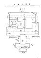
Fig. 1 is in order to implement the block diagram of typical optical communication system of the present invention;
Fig. 2 is a spectrogram of expression carrier wave of the equal intervals of generation according to the present invention;
Fig. 3 is a typical frequency spectrum figure who is illustrated in the carrier wave of the unequal interval that the receiver place that do not implement the system of Fig. 1 when of the present invention can find;
Fig. 4 is the spectrogram of expression according to the main frequency of perturbation process of the present invention;
Fig. 5 is the schematic diagram of expression according to the composition of a circulation in the disturbance program of the present invention; And
Fig. 6 is a flow chart of the receiver microprocessor logic of disturbance program shown in Figure 5.
For a large amount of in lightwave network carrying, for example ten hundreds of simultaneous highspeed users can use a kind of frequency division multiplexing (FDM) technology, and wherein each passage is with different light carrier transmission. Yet this (FDM) technology has the main infringement of a laser phase noise. According to the Lorentz phase noise model, for each passage, from the variation of the power of the interfering signal of other each ways be proportional to the bandwidth of phase noise and be inversely proportional to the intercarrier distance square. Therefore, the carrier wave of equal intervals as shown in Figure 2 will be operable desirable technology. But, be difficult to find a kind of simple method to implement, particularly keep the ideal of the carrier wave of this equal intervals Situation. If modulated carrier wave can be the interval that equates in the FDM technology, in suitably big or small system, carrier wave-noise ratio (CNR) will maintain more than the performance threshold of requirement so, to keep minimum interference.
In the FDM lightwave network, laser stands drift, and this laser drift makes carrier wave be offset to Fig. 3 for example position by the carrier waves of 10 and 11 expressions from their nominal spectral position as shown in Figure 2.The invention provides a kind of in the FDM lightwave system in order to repelling carriers to reach and to keep the technology of the carrier wave of equidistant from distance as shown in Figure 2.According to present technique, each transmitter of system is the FDM signal of its sendaisle of disturbance slowly, and the interference level that each receiver monitoring and measuring is caused by all passages of each side of the passage that receives this signal at needs, and with that feedback information to the original transmitter that sends this signal that needs.So that transmitter will utilize this information to move its own carrier wave frequency, in this way make that interference reduce to minimum.Repelling carriers technology even when phase noise is insignificant, be effective alleviating aspect the adjacent channel interference.The anti-quadratic power rule characteristic of spectrum afterbody (spectral tails) is not main.All need be one outside nominal band (roughly) compression frequency spectrum.
Fig. 1 represents that this system comprises N transceiver 20 in order to implement a block diagram of typical lightwave system of the present invention
1To 20
NAnd one with N the interconnected optical-fiber network 21 of transceiver.For the purpose of illustrating, optical-fiber network 21 can comprise any trimmed book ground Local Area Network (Local Area Network) structure, for example linear bus, loop and star structure etc., but preferred network is star (Star) structure as shown in Figure 1.In Fig. 1, transceiver 20
1Be to represent that with the expansion block diagram form of demonstration it is equivalent to other transceivers 20 of system
2To 20
NThe middle typical structure that occurs.
Each transceiver 20; Comprise a transmitter section 30 and a receiver section 40.Typical transmitter section 30 comprises shown in the figure: a laser 31, in order to be created in the needed carrier wave that from the information signal that transmitter section 30 sends, uses; One frequency control apparatus 32 is in order to provide the carrier frequency (wavelength) of a suitable bias voltage to regulate laser and to be produced by laser 31 in order to disturbance at leisure; One electrical-optical modulator 33 is in order to will be from the carrier wave of laser 31 and information signal modulation from receiving with the associated user of transceiver; And a control-signals generator device 34, in order to produce one along with information signal sends it back the feedback control signal of remote receiver together.Typical receiver section 40 shown in the figure comprises a receiver 41, in order to receive from the information signal of optical-fiber network and suitably to handle the information signal that receives, signal is sent to the terminal use and a microprocessor 42 of hope in a passage that requires, this will be described in more detail hereinafter.
For the work of the present invention of using Fig. 1 is described, can suppose transceiver 20
1The user wish to use the carrier wave 10 and transceiver 20 shown in Fig. 2 by optical-fiber network 21
NThe user communicate.For purposes of illustration, also can suppose transceiver 20
NThe user will use the carrier wave 11 shown in Fig. 2, to provide and transceiver 20
1User's duplex communication.At transceiver 20
1The place, laser 31 is adjusted at its output by frequency control apparatus 32 and produces carrier wave 10.At transceiver 20
NThe place, laser 31 is adjusted at its output by relevant frequency control apparatus 32 and produces carrier wave 11.To any receiver section 40 is ignorant, at transceiver 20
1With 20
NIn each frequency control apparatus 32 also slowly disturbance carrier wave 10 and 11 frequency respectively, at first and then to second near by frequency 51 on the right side slightly, as shown in Figure 4 to the near by frequency 50 on the left side slightly of the existing rated frequency of separately carrier wave 10 and 11.At transceiver 20
1In, from the carrier wave 10 of the slowly disturbance of laser 31 be and the information signal that receives from relevant user 1 (for example by electrooptic modulator (EOM) 33) modulation.From transceiver 20
1The modulated output signal of slowly disturbance of transmitter section 30 through photoconduction 22
1Be sent to optical-fiber network 21(and issue all receiver sections 40 by this punishment), and pass through photoconduction 23 then
NBe sent to transceiver 20
N Receiver section 40.
As mentioned above, in the carrier frequency at any transmitter section 30 places by disturbance: (a) with at random order and therefore all asynchronous with any receiver section, (b) enough slow with respect to the high character rate of the user message signal that sends, so that being received machine part 40, follows the tracks of normally the carrier wave of disturbance.At transceiver 20
N Receiver section 40 in receiver 41, convert the lightwave signal that receives to a corresponding signal of telecommunication and send user N to, for example use a known frequency lock loop simultaneously, easily follow the tracks of from transceiver 20
1The received signal of slowly disturbance.Receiver 41 was also taken a sample the information signal that receives being sent to user N in the past, and measured amplitude of each sampling, so that the valuation of the mean square error of the sample of signal that receives (MSE) can be determined in a relevant microprocessor 42.MSE estimated value for each left side and right position 50 and 51 is used as the indication of the ambient interferences level of each position.
Especially transceiver 20
N Receiver section 40 in receiver 41 measure the amplitude of the sampling that respectively receives, and provide this level indication to the microprocessor 42 relevant with receiver 41.Microprocessor 42 storage is from each amplitude indication of receiver 41, and from then on calculates it in the MSE valuation of received signal disturbance during two near by frequencies 50 shown in Figure 4 and 51.The MSE valuation is the measure error amplitude that is provided for each position 50 and 51 by receiver 41 by getting, with these level values square, calculate and then this square value is sued for peace in the scope of a time interval or intended duration, so that the MSE valuation of each position 50 and 51 to be provided.Then microprocessor 42 transmit one represent this MSE valuation control signal to transceiver 20
NControl-signals generator 34.In the suitable moment, control-signals generator 34 will add in the preamble of the next information signal section that for example is sent to EOM33, to finish to transceiver 20 from the control signal of microprocessor 42
1Duplex communication.Information that this returns and control signal are through photoconduction 22 on carrier wave 11
N, optical-fiber network 21 and photoconduction 23
1Be sent to transceiver 20
1In receiver 41.From the reception information about this MSE valuation, transceiver 20
1 Microprocessor 42 determine which frequency location, 50 or 51 is preferably, because this position provides minimum estimation MSE value.On the other hand, can implement a kind of more accurate repulsion mechanism, proofread and correct with calculated rate by using estimation MSE value gradient.
From top explanation, can see, if carrier wave 10 and 11 drifts to the position shown in Fig. 3, the optimum position of carrier wave 10 will be towards the left side, in the direction of carrier wave 12, will be recently come for a short time from the interference of the signal relevant from the interference of the signal relevant with nearer carrier wave 13 with carrier wave far away 12 because should the place.So carrier wave 10 will move to the position shown in Fig. 2 at leisure, this position is equidistant approx between carrier wave 12 and 13.Similarly, carrier wave 11 will move to the right, because as shown in Figure 3, the MSE valuation relevant with the signal of carrier wave 11 will show from the interference of the signal relevant with carrier wave 13 from the interference of the signal relevant with carrier wave 14 more very.Therefore, carrier wave 11 will move to right at leisure till position as shown in Figure 2, and this position is roughly equidistant between carrier wave 13 and 14.
The contiguous carrier wave also fact of positive their frequency of disturbance may make algorithm cause mistake when decision reduces the required frequency correction of interference level.Yet, be easy to see how the disturbance pattern of selecting approx avoids this problem.For example, in order to select which position to be enough to guarantee that with the Next simple pattern at random of taking a sample it will be correct direction that final average frequency is proofreaied and correct.
Even transmitter is not with another transceiver communication or attempt to begin to communicate by letter, also always send signal and have an advantage, keeping repulsion because that works.Therefore, between transceiver and the configuration of its frequency spectrum, getting in touch of a pine arranged, thereby provide one in order to quicken the chance of call-start process.At present with call out irrelevant transceiver and can change the sub-fraction that expense is monitored the time of its oneself test program, it oneself leaves other carrier wave with repulsion.That transceiver will and look at whether to have determined a passage periodically change between the two in its own transmission that is used for repulsion of monitoring.
Under situation mentioned above, whole carrier system has unsteady all the time, and specific transceiver reason whatsoever, littlely may can move to a new relevant position.For example, a passage may be out of order and then set up again again, perhaps can add system by the passage that some are new.Yet, the position of transceiver and receiver relating to that transceiver before calling in have 10 fens strong correlations between the employed dialing adjustment (dial setting) (current value of FREQUENCY CONTROL).So transceiver might utilize present technique, this technology is utilized this relevant to reduce the starting time.Just can finish the scanning of calling by any suitable known technology in the usefulness prior art with previous order scan band.Priorization can help the most frequent or most important caller in the interested group.
Should be appreciated that control disperses.Although narrated passage and had undemanding ordering for previous all section,, order do not have the major break down generation if changing once in a while yet.And, do not require that each transceiver utilization reduces the chance of starting time.Another advantage that requires each transceiver to keep frequency spectrum to exist is to have avoided the problem of all calling party conflicts.It seems that the desired power of lasting transmission be minimum, and be difficult to imagine those situations, there abundant inadequately " waste " band width configuration on the passage of a free time that is enough to of bandwidth resources.
Logic in order to the microprocessor 42 of implementing present technique is uncomplicated.One typical program of microprocessor 42 logics is shown in Figure 6.Counter 60 is in order to distinguish each beginning of the one of four states shown in Fig. 5.Except that counter 60, another annex memory that only needs in microprocessor 42 is the register that is used for two the MSE valuations relevant with position 50 and 51 (not shown, but by square frame 61 expressions).
Be the explanation of a most preferred embodiment above should be understood that, rather than, can make other and other modification that belong in the spirit and scope of the present invention in order to limit.For example shown in Figure 1, in transmitter section 30, can adopt laser modulator 35 to come direct modulated laser 31, with through relevant photoconduction 22 from user's input signal and signal combination from frequency control apparatus 32 and control-signals generator 34
ⅰTransmission.Just do not needed EOM33 in this case.As previously mentioned, except the star structure of being narrated, also can adopt other system and device.
Claims (3)
1, a kind of transceiver that in frequency division multiplexing (FDM) light-wave communication system, uses, this transceiver comprises:
One transmitter section (30), it comprises:
In order to produce the device (31) of a normal light wave carrier signal signal of being scheduled to; And
In order to will be from the normal light wave carrier signal signal of generation device and the device (33-35) that remains to be sent to the information signal modulation of remote transceiver from transmitter section;
It is characterized in that this transceiver also comprises:
Give the device (32) of generation device in order to produce control signal, so that described generation device in such a way the wave carrier signal of disturbance normal light at leisure signal to one first near by frequency in a side of this specified carrier signal, making the ambient interferences of collecting be received machine examination measures, drawing a control signal changing the position of this carrier wave, and with this carrier wave location more advantageously in ambient interferences.
2, transceiver according to claim 1, this transceiver also comprises:
One receiver section,
It is characterized in that this receiver section comprises:
One receiver, its light-wave information signal response to sending by remote transceiver, the information signal modulation of being sent to this receiver section specified one second normal light wave carrier signal signal and by this remote transceiver, while is this second light wave carrier signal of disturbance at leisure, in order to the light-wave information signal demodulation that will receive, with one of the system of transferring to relevant user, and according to demodulated information signal work to produce an independent output signal, can realize that according to this output signal the correction of carrier wave moves, and
One processor, it is to the output signal response from receiver, to determine the designator of an interference level, and realize proofreading and correct and move to frequency with low interference level in order to produce a control signal, and be sent to the modulating device of transmitter section, in modulated information signal, to be sent back to remote transceiver.
3, a kind of in frequency division multiplexing (FDM) light-wave communication system the method for transmission signals, this method comprises the steps:
With first of the system first subscriber-related transceiver place,
(a) produce a normal light wave carrier signal signal; And
(b) with specified carrier wave lightwave signal and the information signal modulation that receives from first user;
It is characterized in that this method also comprises the following steps:
(c) near the specified carrier wave lightwave signal that will in step (a), produce disturbance at leisure first user's normal light wave carrier signal signal; And
At the one and second subscriber-related second remote transceiver place,
(d) the modulated information signal demodulation that will receive from first transceiver being sent to second user, and is sequentially taken a sample demodulated information signal, so that produce the control signal that promotes advantageously to change carrier position; And
(e) carrier control signal is sent it back first transceiver, move to the adjacent carriers frequency that to draw from this carrier control signal in order to this nominal carrier frequency that will in step (a), produce before at repeating step (b) to (e) during the next cycle period.
Applications Claiming Priority (2)
| Application Number | Priority Date | Filing Date | Title |
|---|---|---|---|
| US07/034,135 US4800555A (en) | 1987-03-03 | 1987-03-03 | Technique for repelling carriers in optical communications to minimize mutual interference |
| US034,135 | 1987-03-03 |
Publications (1)
| Publication Number | Publication Date |
|---|---|
| CN88101159A true CN88101159A (en) | 1988-09-21 |
Family
ID=21874532
Family Applications (1)
| Application Number | Title | Priority Date | Filing Date |
|---|---|---|---|
| CN198888101159A Pending CN88101159A (en) | 1987-03-03 | 1988-03-02 | Make the phase mutual interference reduce to minimum technology in order to repelling carriers in the optical communication |
Country Status (7)
| Country | Link |
|---|---|
| US (1) | US4800555A (en) |
| EP (1) | EP0281306B1 (en) |
| JP (1) | JPH0646722B2 (en) |
| KR (1) | KR910003417B1 (en) |
| CN (1) | CN88101159A (en) |
| CA (1) | CA1275513C (en) |
| DE (1) | DE3887361T2 (en) |
Families Citing this family (26)
| Publication number | Priority date | Publication date | Assignee | Title |
|---|---|---|---|---|
| FR2642924B1 (en) * | 1989-02-03 | 1991-04-12 | Comp Generale Electricite | COMMUNICATION NETWORK ON OPTICAL FIBERS WITH FREQUENCY MULTIPLEXING |
| US5202782A (en) * | 1990-01-19 | 1993-04-13 | Canon Kabushiki Kaisha | Optical communication method and optical communication system |
| FR2672168B1 (en) * | 1991-01-24 | 1993-04-09 | Alcatel Nv | METHOD AND DEVICE FOR RELATIVE POSITIONING OF A FREQUENCY, ESPECIALLY OPTICAL. |
| US5239400A (en) * | 1991-07-10 | 1993-08-24 | The Arizona Board Of Regents | Technique for accurate carrier frequency generation in of DM system |
| FR2681996B1 (en) * | 1991-09-26 | 1993-11-12 | Alcatel Nv | OPTICAL FREQUENCY TRACKING METHOD AND FREQUENTIAL CHANNEL COMMUNICATION NETWORK APPLYING THIS METHOD. |
| GB2294372A (en) * | 1994-10-22 | 1996-04-24 | Coe Limited | Optical network |
| US5949562A (en) * | 1994-11-30 | 1999-09-07 | Canon Kabushiki Kaisha | Transmission wavelength control method permitting efficient wavelength multiplexing, optical communication method, optical transmitter, optical transmitter-receiver apparatus, and optical communication system |
| JP3305137B2 (en) * | 1994-11-30 | 2002-07-22 | キヤノン株式会社 | Optical transmission device, optical transmission / reception device, optical communication system, transmission wavelength control method, and optical communication method |
| DE69628486T2 (en) * | 1995-03-23 | 2004-05-13 | Canon K.K. | Wavelength assignment in an optical transmission system |
| US5798858A (en) * | 1996-02-01 | 1998-08-25 | Lucent Technologies Inc. | Method and apparatus for reducing adverse effects of optical beat interference in optical communication systems |
| GB2315938B (en) * | 1996-08-01 | 2001-02-28 | Northern Telecom Ltd | Optical transmission system fault analysis |
| US7154914B1 (en) | 1998-03-05 | 2006-12-26 | Forster Energy Llc | Through-timing of data transmitted across an optical communications system utilizing frequency division multiplexing |
| US6529303B1 (en) * | 1998-03-05 | 2003-03-04 | Kestrel Solutions, Inc. | Optical communications networks utilizing frequency division multiplexing |
| US20020024694A1 (en) * | 2000-05-12 | 2002-02-28 | Newell Laurence J. | Control channel for an optical communications system utilizing frequency division multiplexing |
| US7228077B2 (en) * | 2000-05-12 | 2007-06-05 | Forster Energy Llc | Channel gain control for an optical communications system utilizing frequency division multiplexing |
| US20020012146A1 (en) * | 2000-06-01 | 2002-01-31 | Newell Laurence J. | Synchronizing nodes in an optical communications system utilizing frequency division multiplexing |
| US7096257B2 (en) * | 2000-06-15 | 2006-08-22 | Forster Energy Llc | Automatic assignment of addresses to nodes in a network |
| US7437654B2 (en) * | 2000-11-29 | 2008-10-14 | Lucent Technologies Inc. | Sub-packet adaptation in a wireless communication system |
| US20020110157A1 (en) * | 2001-02-14 | 2002-08-15 | Kestrel Solutions | Method and apparatus for providing a gigabit ethernet circuit pack |
| JP2002246683A (en) * | 2001-02-15 | 2002-08-30 | Toshiba Corp | Optical transmitter and optical transmission system |
| EP1271825A1 (en) * | 2001-06-25 | 2003-01-02 | Lucent Technologies Inc. | Method and system for multiplexed optical information transport |
| EP1776792A4 (en) * | 2004-08-11 | 2012-01-04 | Tyco Electronics Subsea Comm | System and method for spectral loading an optical transmission system |
| US8718476B2 (en) * | 2008-02-27 | 2014-05-06 | Xtera Communications, Inc. | Tunable optical discriminator |
| US10673528B1 (en) * | 2019-02-25 | 2020-06-02 | Huawei Technologies Co., Ltd. | Methods and apparatuses for controlling optical signals in optical networks |
| US11228366B2 (en) * | 2019-02-28 | 2022-01-18 | Ntt Electronics Corporation | Optical transmission characteristics estimation method, optical transmission characteristics estimation system, and optical transmission characteristics compensation system |
| US11271659B1 (en) * | 2020-08-24 | 2022-03-08 | Huawei Technologies Co., Ltd. | Systems and methods for phase noise mitigation in optical superchannels |
Family Cites Families (12)
| Publication number | Priority date | Publication date | Assignee | Title |
|---|---|---|---|---|
| US3983484A (en) * | 1974-12-06 | 1976-09-28 | Nihon Dengyo Co., Ltd. | Multichannel signal transmitting and receiving apparatus |
| JPS5344110A (en) * | 1976-10-05 | 1978-04-20 | Saibanetsuto Kougiyou Kk | System for synchronizing and synthesizing frequency of radio transmitter*receiver |
| CA1123528A (en) * | 1977-07-12 | 1982-05-11 | Elmer H. Hara | Frequency division multiplexing system for optical transmission of broadband signals |
| IT1159851B (en) * | 1978-06-20 | 1987-03-04 | Cselt Centro Studi Lab Telecom | IMPROVEMENTS IN WAVE LENGTH DIVISION TRANSMISSION SYSTEMS |
| US4225851A (en) * | 1979-03-22 | 1980-09-30 | General Electric Company | Self-calibrated subcarrier telemetry system |
| DE3131892C2 (en) * | 1980-08-12 | 1984-09-06 | Mitsubishi Denki K.K., Tokio/Tokyo | Frequency separator |
| US4579417A (en) * | 1983-01-28 | 1986-04-01 | University Of Delaware | Apparatus for optical fiber communications using standing wave acousto-optical modulator |
| GB2142796B (en) * | 1983-07-01 | 1986-07-16 | Standard Telephones Cables Ltd | Optical fdm system |
| US4592043A (en) * | 1983-07-08 | 1986-05-27 | At&T Bell Laboratories | Wavelength division multiplexing optical communications systems |
| JPS60242739A (en) * | 1984-05-17 | 1985-12-02 | Nec Corp | Frequency multiplex optical transmitter |
| US4680810A (en) * | 1985-06-28 | 1987-07-14 | American Telephone And Telegraph Company, At&T Bell Labs | Means for controlling a semiconductor device and communication system comprising the means |
| US4691385A (en) * | 1985-09-05 | 1987-09-01 | Caterpillar Industrial Inc. | Optical communication apparatus for a vehicle |
-
1987
- 1987-03-03 US US07/034,135 patent/US4800555A/en not_active Expired - Lifetime
-
1988
- 1988-02-16 CA CA000558995A patent/CA1275513C/en not_active Expired - Fee Related
- 1988-02-24 EP EP88301556A patent/EP0281306B1/en not_active Expired - Lifetime
- 1988-02-24 DE DE3887361T patent/DE3887361T2/en not_active Expired - Fee Related
- 1988-03-02 CN CN198888101159A patent/CN88101159A/en active Pending
- 1988-03-03 KR KR1019880002176A patent/KR910003417B1/en not_active IP Right Cessation
- 1988-03-03 JP JP63048805A patent/JPH0646722B2/en not_active Expired - Lifetime
Also Published As
| Publication number | Publication date |
|---|---|
| JPH0646722B2 (en) | 1994-06-15 |
| KR880012036A (en) | 1988-10-31 |
| EP0281306A3 (en) | 1990-08-16 |
| EP0281306B1 (en) | 1994-01-26 |
| DE3887361T2 (en) | 1994-07-21 |
| US4800555A (en) | 1989-01-24 |
| KR910003417B1 (en) | 1991-05-30 |
| DE3887361D1 (en) | 1994-03-10 |
| CA1275513C (en) | 1990-10-23 |
| JPS63253739A (en) | 1988-10-20 |
| EP0281306A2 (en) | 1988-09-07 |
Similar Documents
| Publication | Publication Date | Title |
|---|---|---|
| CN88101159A (en) | Make the phase mutual interference reduce to minimum technology in order to repelling carriers in the optical communication | |
| US5299044A (en) | Ranging method for use in TDMA systems on tree-and-branch optical networks | |
| DE69834999T2 (en) | Quality monitoring system of optical signals with different bit rates | |
| EP0486874B1 (en) | Multiplex digital communication system for transmitting channel identification information | |
| EP0616443A2 (en) | Telecommunication system with ranging | |
| US5220448A (en) | Bit and frame synchronization unit for an access node of optical transmission equipment | |
| EP0216839B1 (en) | Optical signal processing | |
| Shake et al. | Simple Q factor monitoring for BER estimation using opened eye diagrams captured by high-speed asynchronous electrooptical sampling | |
| EP0489444B1 (en) | Method for transmission and receipt of coherent light signals | |
| JPH0799484A (en) | Channel selection system and data receiver | |
| CN1741432B (en) | Optical code division multiplexing communication method and system,coding device and decoding device | |
| JPH0767155A (en) | Optical system | |
| EP0486931A2 (en) | Distance-measuring method and transmitting and receiving station for carrying out the same | |
| Poggiolini et al. | Theory of subcarrier encoding of packet headers in quasi-all-optical broadband WDM networks | |
| US7064814B2 (en) | Chromatic dispersion measurement and compensation | |
| Su et al. | Performance of WDMA networks with baseband data packets and subcarrier multiplexed control channels | |
| DE60103359T2 (en) | Method for adjusting time delays and device for synchronizing channels in a WDM system | |
| CA1238432A (en) | Digital radio communication system | |
| KR20010000854A (en) | Burst-mode clock recovery module | |
| Shake et al. | WDM signal monitoring utilizing asynchronous sampling and wavelength selection based on thermo-optic switch and AWG | |
| CN108834001A (en) | A kind of electromagnetic remote metering system and method | |
| JP2002525971A (en) | Apparatus and method for controlling sampling rate in a data transmission system | |
| Ims et al. | 10 Gbit/s Optical Transmisson beyond Dispersion Limit | |
| JPH05347603A (en) | Channel selection method in optical frequency division multiplex transmission | |
| CN114938245A (en) | Distributed multi-antenna cooperative phase stabilization method and device for future broadband wireless communication |
Legal Events
| Date | Code | Title | Description |
|---|---|---|---|
| C06 | Publication | ||
| PB01 | Publication | ||
| C10 | Entry into substantive examination | ||
| SE01 | Entry into force of request for substantive examination | ||
| RJ01 | Rejection of invention patent application after publication |