CN219093912U - Welding head for tin adding welding and welding device - Google Patents
Welding head for tin adding welding and welding device Download PDFInfo
- Publication number
- CN219093912U CN219093912U CN202223435219.3U CN202223435219U CN219093912U CN 219093912 U CN219093912 U CN 219093912U CN 202223435219 U CN202223435219 U CN 202223435219U CN 219093912 U CN219093912 U CN 219093912U
- Authority
- CN
- China
- Prior art keywords
- welding
- welding head
- head
- axis
- soldering
- Prior art date
- Legal status (The legal status is an assumption and is not a legal conclusion. Google has not performed a legal analysis and makes no representation as to the accuracy of the status listed.)
- Active
Links
Images


Landscapes
- Arc Welding In General (AREA)
Abstract
The utility model relates to the technical field of welding devices, and discloses a welding head for tin adding welding and a welding device. The soldering head for tin adding soldering comprises: the welding head can move on the X axis, the Y axis and the Z axis so that the welding head can move to a welding position on the junction box, the bottom end surface of the welding head can be adhered with tin wires, and the welding head can be heated to a preset temperature; the thermocouple sensor is fixedly connected with the welding head and is positioned on one side of the welding head, the measuring end of the thermocouple sensor is positioned above the bottom end surface of the welding head, the distance H between the measuring end of the thermocouple sensor and the bottom end surface of the welding head is 3mm-20mm, and the thermocouple sensor is used for detecting the heating temperature of the welding head. The welding head for tin-adding welding can prolong the service life of the welding head and reduce the replacement frequency of the welding head, thereby shortening the downtime of the whole machine and reducing the welding cost.
Description
Technical Field
The utility model relates to the technical field of welding devices, in particular to a welding head for tin adding welding and a welding device.
Background
At present, in order to ensure the welding quality between the bus bar and the junction box in the photovoltaic module, a tin-adding welding mode is generally adopted, namely, a welding head is heated during welding, so that tin wires adhered on the bottom end face of the welding head are thermally fused for welding. Wherein the heating temperature of the welding joint is detected by a sensor.
However, when the current sensor is arranged on the welding head, the detection position of the sensor on the welding head is not considered, so that the sensor cannot accurately detect the actual heating temperature of the welding head, a larger gap is formed between the detection value of the sensor and the actual heating temperature value of the welding head, the actual heating temperature value of the welding head is higher, the detection value is equal to the preset heating temperature value at the moment, the welding head is easy to be in a high-temperature and high-temperature state, the service life of the welding head is influenced, the frequency of replacing the welding head is higher, and further the downtime of the whole machine is longer and the welding cost is higher.
Therefore, there is a need for a soldering tip and a soldering apparatus for soldering, which can solve the above problems.
Disclosure of Invention
An object of the present utility model is to provide a soldering head for soldering, which can improve the service life of the soldering head and reduce the replacement frequency of the soldering head.
To achieve the purpose, the utility model adopts the following technical scheme:
a soldering tip for soldering, comprising:
the welding head can move on an X axis, a Y axis and a Z axis so that the welding head can move to a welding position on the junction box, the bottom end surface of the welding head can be adhered with tin wires, and the welding head can be heated to a preset temperature;
the thermocouple sensor is fixedly connected with the welding head and is positioned on one side of the welding head, the measuring end of the thermocouple sensor is positioned above the bottom end face of the welding head, the distance H between the measuring end of the thermocouple sensor and the bottom end face of the welding head is 3mm-20mm, and the thermocouple sensor is used for detecting the heating temperature of the welding head.
Further, a distance H between a measuring end of the thermocouple sensor and a bottom end surface of the welding head is 5mm.
Further, the thermocouple sensor is fixedly connected to the welding head through a plurality of bending plates.
Further, a wiring groove is further formed in the welding head and used for installing a connecting wire on the thermocouple sensor.
Further, the bottom end surface of the welding head is provided with a clamping groove, an insert is arranged in the clamping groove in a clamping mode, the insert can be stuck to molten tin wires, and after the insert is clamped in the clamping groove, a tin wire placing groove is formed in the part, located below the insert, of the clamping groove.
Further, the welding head is made of molybdenum alloy materials.
Another object of the present utility model is to provide a welding device, which can make the downtime of the whole machine shorter and the welding cost lower.
To achieve the purpose, the utility model adopts the following technical scheme:
a welding device including a soldering tip as described above, the welding tip being further rotatable about a Z-axis, the welding device further comprising:
the heating component is used for heating the welding head so as to enable the welding head to reach the preset temperature;
the welding head comprises a first driving piece, a second driving piece, a third driving piece and a fourth driving piece, wherein the first driving piece is used for driving the welding head to rotate around a Z axis, and the second driving piece, the third driving piece and the fourth driving piece are respectively used for driving the welding head to move along the X axis, the Y axis and the Z axis.
Further, the welding device further comprises a water cooling member for water-cooling the welding head, the water cooling member comprising:
one end of the first metal piece is fixedly connected with the welding head;
the cooling device comprises a second metal piece and a plurality of runners extending along a Z axis, wherein the other end of the first metal piece is fixedly connected to the second metal piece, the runners are arranged on the inner side of the second metal piece at intervals in parallel, and cooling water flows in the runners.
Further, the welding device further comprises an air cooling part for cooling the welding head, the air cooling part moves along with the movement of the welding head, and the air cooling part comprises:
the air pipe is used for blowing the cold air to the welding head.
Further, the welding device further includes:
and the CCD camera is used for detecting welding points at the welding position on the junction box before welding and the welding position after welding.
The beneficial effects of the utility model are as follows:
the welding head moves on the X axis, the Y axis and the Z axis so that the welding head can accurately move to the welding position and cover the welding position, the welding head is heated to a preset temperature so as to enable tin wires on the welding head at the welding position to be hot melted, then the heating is stopped and the welding head is cooled so as to enable the tin wires after the hot melting at the welding position to be solidified, and therefore tin adding welding between the bus bar and the junction box is completed; meanwhile, the thermocouple sensor is fixedly connected with the welding head and is positioned at one side of the welding head, the measuring end of the thermocouple sensor is positioned above the bottom end surface of the welding head, the distance H between the measuring end of the thermocouple sensor and the bottom end surface of the welding head is 3mm-20mm, the thermocouple sensor can accurately detect the actual heating temperature of the welding head, so that the detection value of the thermocouple sensor is basically equal to the actual heating temperature of the welding head, the problem that the actual heating temperature value of the welding head is higher, and the detection value of the thermocouple sensor is equal to the preset heating temperature value at the moment can be avoided, the welding head is always in a high-temperature state, the service life of the welding head is prolonged, the frequency of replacing the welding head is reduced, and the whole machine halt time of the welding head for tin adding welding is shorter, and the welding cost is lower.
Drawings
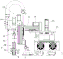
FIG. 1 is a schematic view of a weld head according to the present utility model;
FIG. 2 is a schematic view of a welding device according to the present utility model;
FIG. 3 is a side view of a welding apparatus provided by the present utility model;
FIG. 4 is a schematic diagram of an assembly structure of a first driving member, a second driving member and a welding head according to the present utility model;
fig. 5 is an enlarged partial schematic view at a in fig. 4.
Reference numerals:
1-a welding head; 111-a clamping groove; 112-tin wire placing grooves; 2-a heating assembly; a 3-CCD camera; 4-pressing the component; 41-guide posts; 42-elastic member; 43-pressing plate; 44-a fixed block; 5-a first connection plate; 6-water cooling piece; 61-a first metal piece; 62-a second metal piece; 71-trachea; 8-an insert; 10-a first driving member; 11-a second connection plate; 12-a second driving member; 13-a third connection plate; 14-a third drive member; 15-a fourth connecting plate; 16-fourth drive member; 17-thermocouple sensor; 18-bending the plate.
Detailed Description
In order to make the technical problems solved, the technical scheme adopted and the technical effects achieved by the utility model more clear, the technical scheme of the utility model is further described below by a specific embodiment in combination with the attached drawings.
In the description of the present utility model, unless explicitly stated and limited otherwise, the terms "connected," "connected," and "fixed" are to be construed broadly, and may be, for example, fixedly connected, detachably connected, or integrally formed; can be mechanically or electrically connected; can be directly connected or indirectly connected through an intermediate medium, and can be communicated with the inside of two elements or the interaction relationship of the two elements. The specific meaning of the above terms in the present utility model will be understood in specific cases by those of ordinary skill in the art.
In the present utility model, unless expressly stated or limited otherwise, a first feature "above" or "below" a second feature may include both the first and second features being in direct contact, as well as the first and second features not being in direct contact but being in contact with each other through additional features therebetween. Moreover, a first feature being "above," "over" and "on" a second feature includes the first feature being directly above and obliquely above the second feature, or simply indicating that the first feature is higher in level than the second feature. The first feature being "under", "below" and "beneath" the second feature includes the first feature being directly under and obliquely below the second feature, or simply means that the first feature is less level than the second feature.
In the description of the present embodiment, the terms "upper", "lower", "left", "right", and the like are orientation or positional relationships based on those shown in the drawings, and are merely for convenience of description and simplicity of operation, and are not intended to indicate or imply that the structures or elements referred to must have a specific orientation, be constructed and operated in a specific orientation, and thus should not be construed as limiting the utility model. Furthermore, the terms "first," "second," and the like, are used merely for distinguishing between descriptions and not for distinguishing between them.
At present, when the sensor is arranged on the welding head, the specific detection position of the sensor on the welding head is not considered, so that the sensor cannot accurately detect the actual heating temperature of the welding head, a larger gap is formed between the detection value of the sensor and the actual heating temperature value of the welding head, the actual heating temperature value of the welding head is higher easily, the detection value is equal to the preset heating temperature value, the welding head is easily in a high-temperature state, the service life of the welding head is influenced, the frequency of replacing the welding head is higher, and the whole machine halt time of the welding head for tin-adding welding is longer and the welding cost is higher.
Example 1
For this purpose, in the present embodiment, a soldering head for soldering is proposed, which includes a soldering head 1 and a thermocouple sensor 17 as shown in fig. 1 and 2; the welding head 1 can move on an X axis, a Y axis and a Z axis so that the welding head 1 can move to a welding position on the junction box for welding, and the bottom end surface of the welding head 1 can be adhered with tin wires; the welding head 1 can be heated to a preset temperature so that tin wires adhered on the bottom end surface of the welding head 1 can be hot melted for tin adding welding; the thermocouple sensor 17 is fixedly connected with the welding head 1 and is positioned on one side of the welding head 1, the measuring end of the thermocouple sensor 17 is positioned above the bottom end face of the welding head 1, the distance H between the measuring end of the thermocouple sensor 17 and the bottom end face of the welding head 1 is 3mm-20mm, and the thermocouple sensor 17 is used for detecting the heating temperature of the welding head 1. Wherein the spacing H is specifically indicated by the label H in fig. 1, and the X-axis, Y-axis, and Z-axis are specifically indicated by arrows in fig. 2.
The welding head 1 is moved on the X axis, the Y axis and the Z axis so that the welding head 1 can accurately move to the welding position and cover the welding position, the welding head 1 is heated to a preset temperature so as to enable tin wires on the welding head 1 at the welding position to be melted, then the heating is stopped and the welding head 1 is cooled so as to enable the tin wires after being melted at the welding position to be solidified, and therefore tin-adding welding between the bus bar and the junction box is completed. In this embodiment, the welding of the bus bar to the junction box is a common assembly method of the photovoltaic module in the prior art, and therefore, a detailed description of a specific welding principle between the bus bar and the junction box is not repeated here.
The soldering head in the present embodiment considers the detection position of the thermocouple sensor 17 on the soldering head 1 with respect to the prior art; by enabling the distance H between the measuring end of the thermocouple sensor 17 and the bottom end surface of the welding head 1 to be 3mm-20mm, the position can enable the thermocouple sensor 17 to accurately detect the actual heating temperature of the welding head 1, so that the detection value of the thermocouple sensor 17 is basically equal to the actual heating temperature of the welding head 1, the problem that the actual heating temperature value of the welding head 1 is higher, and the detection value of the thermocouple sensor 17 is equal to the preset heating temperature value at the moment can be avoided, the welding head 1 is always in a high-heat and high-temperature state, the service life of the welding head 1 is prolonged, the frequency of replacing the welding head 1 is reduced, and then the whole machine halt time of a welding head for tin adding welding is shorter and the welding cost is lower.
Specifically, as shown in table 1, which is a table showing the service lives of the respective welding heads at different pitches H, when the pitch H between the measuring end of the thermocouple sensor 17 and the bottom end surface of the welding head 1 is set in a range other than 3mm to 20mm, that is, H < 3mm or H > 20mm, the average service life of the welding head 1 is 22706 times; in the embodiment, test verification of service lives of the three welding heads 1 with different pitches H are respectively carried out; wherein, three different pitches H are h=3mm, h=5mm, h=8mm respectively; when h=3 mm, that is, when the distance between the measuring end of the thermocouple sensor 17 and the bottom end surface of the welding head 1 is 3mm, the welding head 1 will send out a replacement alarm after the number of times 63500 of welding is performed, that is, the welding head 1 is damaged at this time, and the welding head 1 needs to be replaced; when h=5 mm, that is, when the distance between the measuring end of the thermocouple sensor 17 and the bottom end surface of the welding head 1 is 5mm, the welding head 1 gives a replacement alarm after the number of times 64520 of welding is performed, that is, when the welding head 1 is damaged, the welding head 1 needs to be replaced; when h=8 mm, that is, when the distance between the measuring end of the thermocouple sensor 17 and the bottom end surface of the bonding head 1 is 8mm, the bonding head 1 gives a replacement alarm after the number of times 62255 of welding is performed, that is, the bonding head 1 is damaged at this time, and the bonding head 1 needs to be replaced.
TABLE 1

As shown in table 1, according to the above test procedure, it was found that setting the distance H between the measuring end of the thermocouple sensor 17 and the bottom end surface of the bonding head 1 to be in the range of 3mm to 20mm can increase the average life of the bonding head 1 to about 6 ten thousand times, and in this embodiment, the life of the bonding head 1 can be increased by at least about 2 to 3 times, compared to the current setting the distance H between the measuring end of the thermocouple sensor 17 and the bottom end surface of the bonding head 1 to be in the range of 3mm to 20 mm.
In this embodiment, as shown in table 1, the distance H between the measuring end of the thermocouple sensor 17 and the bottom end surface of the welding head 1 may be preferably 5mm, so that the welding head 1 may obtain a longer service life to the greatest extent, and further reduce the replacement frequency of the welding head 1 to the greatest extent, and ensure that the whole machine has a higher working efficiency.
Further, as shown in fig. 1, the thermocouple sensor 17 is fixedly connected to the welding head 1 through a plurality of bending plates 18, that is, the bending plates 18 can press the thermocouple sensor 17 against the side surface of the welding head 1, and both ends of the bending plates 18 are fixedly connected to the welding head 1, so that the thermocouple sensor 17 is fixed to the welding head 1. The plurality of bending plates 18 are arranged at intervals, so that the thermocouple sensor 17 can be stably fixed on the welding head 1. In the present embodiment, the number of the bending plates 18 is two. The specific structure and dimensions of the bending plate 18 are not limited, as long as the thermocouple sensor 17 is securely mounted on the bonding head 1 by the bending plate 18.
Specifically, a wiring groove is further provided on the bonding head 1, and the wiring groove is used for installing the connection wire on the thermocouple sensor 17, so that the connection wire on the thermocouple sensor 17 can be unified. The welding head 1 is made of molybdenum alloy materials, and the molybdenum alloy has the characteristics of quick heating, small temperature error, wear resistance and small heating deformation. In other embodiments, the welding head 1 may be made of other materials, which is not limited herein.
Further, as shown in fig. 1, a clamping groove 111 is formed on the bottom end surface of the welding head 1, the clamping groove 111 is used for clamping an insert 8, and the insert 8 can adhere to molten tin wires so as to be convenient for taking up the tin wires; after the insert 8 is clamped in the clamping groove 111, a tin wire placing groove 112 is formed in a portion, located below the insert 8, of the clamping groove 111, and the tin wire placing groove 112 can provide a placeable space so as to be capable of accommodating tin wires in the tin wire placing groove 112. The insert 8 may be made of a tin-bondable material, in particular, to enable better bonding of tin wires.
Example two
The embodiment provides a welding device, which comprises a welding head for tin adding welding in the first embodiment; specifically, as shown in fig. 2 and 3, the welding device further includes a water cooling member 6 for water-cooling the welding head 1; the water cooling member 6 includes a first metal member 61, a second metal member 62, and a plurality of flow channels extending along the Z-axis; one end of the first metal piece 61 is fixedly connected with the welding head 1, the other end of the first metal piece 61 is fixedly connected with the second metal piece 62, a plurality of flow channels are arranged on the inner side of the second metal piece 62 at intervals in parallel, and cooling water flows in the flow channels. Wherein, each runner can be integrally formed and arranged on the inner side of the second metal piece 62, or can be arranged on the inner side of the second metal piece 62 by adopting a split type structure.
Specifically, when the welding head 1 needs to be water-cooled, the cooling water in each flow passage can absorb the heat conducted from the first metal piece 61 to the second metal piece 62, so that the heat on the welding head 1 connected with the first metal piece 61 is reduced, and the purpose of water-cooling the welding head 1 is achieved.
It should be noted that, in the whole welding process, the welding head 1 needs to be cooled twice, and the first cooling is that when the welding head 1 is adhered with tin wires, namely after the welding head 1 is heated for the first time, the insert 8 clamped at the bottom end surface of the welding head 1 can be heated to adhere the tin wires with melted surfaces, and then the welding head 1 is cooled rapidly for the first time, so that the insert 8 and the tin wires are solidified into a whole, and further the tin wires are adhered on the bottom end surface of the welding head 1; the second cooling is performed when the welding head 1 performs welding, that is, when the welding head 1 descends to completely cover the welding position along the Z axis, the welding head 1 is heated for the second time, so that the tin wire on the insert 8 is quickly melted and overflowed to the welding position, and then the welding head 1 is quickly cooled for the second time, so that the tin wire at the welding position can be quickly solidified, and the welding work is completed.
Further, the welding device also comprises an air cooling piece, which is used for cooling the welding joint 1 by air, and moves along with the movement of the welding joint 1; as shown in fig. 2 and 3, the air cooling member includes an air duct 71, cold air flows in the air duct 71, and an air outlet of the air duct 71 is located at one side of the bonding head 1, and the air duct 71 is used to blow the cold air to the bonding head 1. The shape of the air pipe 71 is bent, so that the air outlet of the air pipe 71 can be ensured to be opposite to one side of the welding head 1 while the air pipe 71 does not interfere with other structures in the welding device, and the cooling effect of the air-cooled part on the welding head 1 is good.
By arranging the two cooling parts, namely the water cooling part 6 and the air cooling part, the butt welding joint 1 can be simultaneously subjected to water cooling and air cooling, so that the cooling effect of the butt welding joint 1 is good, and the rapid cooling of the butt welding joint 1 is realized; meanwhile, the specific cooling mode of the butt welding joint 1 can be properly selected according to the actual cooling requirement, so that the cooling mode of the butt welding joint 1 is flexible.
Further, as shown in fig. 2 and 3, the welding device further includes a CCD camera 3, the CCD camera 3 being configured to detect a specific position of the welding position on the junction box before welding, so that the welding head 1 can be accurately moved to the welding position on the junction box according to the detection result of the CCD camera 3; and, the CCD camera 3 is also used for detecting the welding spot at the welding position after welding to detect the actual welding effect between the junction box and the bus bar; meanwhile, the CCD camera 3 can also detect the specific placement position of the tin wire, so that the welding head 1 can accurately move to the tin wire and adsorb the tin wire on the insert 8 on the bottom end surface of the welding head 1.
Specifically, as shown in fig. 2 and 3, the welding device further comprises a pressing component 4, the pressing components 4 are arranged on two opposite sides of the welding head 1, the pressing components 4 can move along with the movement of the welding head 1, the pressing components 4 are used for horizontally pressing the top end face of the junction box before the welding of the welding head 1, the welding head 1 is lowered along the Z axis and covers the welding position for welding, so that the problem that the junction box inclines or shakes in the whole welding process can be avoided, and the welding quality between the bus bar and the junction box can be guaranteed.
Further, as shown in fig. 4 and 5, the welding head 1 can also rotate around the Z axis, the welding device further includes a first connecting plate 5, the second metal piece 62 is fixedly disposed on the first connecting plate 5, and the first connecting plate 5 can drive the welding head 1 to move on the X axis, the Y axis and the Z axis and rotate around the Z axis, that is, the first connecting plate 5 is synchronous with the movement of the welding head 1; the pressing component 4 comprises a guide pillar 41, an elastic piece 42, a fixed block 44 and a pressing plate 43, wherein the fixed block 44 is fixedly connected to the first connecting plate 5 and located on one side of the welding head 1, one end of the guide pillar 41 is fixedly connected to the fixed block 44, one end of the pressing plate 43 is slidably connected with the other end of the guide pillar 41, the other end of the pressing plate 43 can extend towards the welding head 1, the elastic piece 42 is sleeved on the guide pillar 41 and located between the fixed block 44 and the pressing plate 43, and the bottom end surface of the pressing plate 43 is lower than the bottom end surface of the welding head 1, so that the pressing plate 43 can be horizontally and elastically pressed on the top end surface of the junction box before the welding head 1.
Specifically, when the first connecting plate 5 drives the welding head 1 and the pressing component 4 to move to the welding position, the welding head 1 and the pressing component 4 continue to move downwards along the Z axis, and when the pressing plate 43 in the pressing component 4 moves horizontally and is elastically pressed on the top end surface of the junction box, the welding head 1 does not cover the welding position completely; and then the welding head 1 and the pressing component 4 continue to move downwards along the Z axis until the welding head 1 completely covers the welding position, in the process, the pressing plate 43 can move upwards along the Z axis on the guide post 41 under the abutting action of the junction box so as to compress the elastic piece 42, so that the pressing plate 43 can be pressed on the top end surface of the junction box under the action of the elastic force of the elastic piece 42, and further the elastic pressing of the junction box is realized, so that the junction box can be better protected. In this embodiment, the elastic member 42 may be a compression spring.
It should be noted that, after the welding is completed, the first connecting plate 5 drives the welding head 1 and the pressing component 4 to move upwards along the Z axis, the welding head 1 will be separated from the junction box first step relative to the pressing plate 43, that is, the pressing plate 43 can be always pressed against the junction box in the whole process of moving the welding head 1 upwards along the Z axis to avoid the junction box being lifted upwards under the action force of moving the welding head 1 upwards along the Z axis, so as to ensure that the junction box will not deflect or shake after the welding is completed.
Specifically, as shown in fig. 2 and 3, the welding apparatus further includes a heating assembly 2, a first driving member 10, a second driving member 12, a third driving member 14, and a fourth driving member 16; wherein, the heating component 2 is used for heating the welding head 1 so that the welding head 1 can reach a preset temperature; the first driving member 10 is used for driving the welding head 1 to rotate around the Z axis, and the second driving member 12, the third driving member 14 and the fourth driving member 16 are used for driving the welding head 1 to move along the Z axis, the Y axis and the X axis respectively. In this embodiment, the heating assembly 2 may be a variable pressure heating mechanism or other heating mechanisms commonly used in the art, which is not limited herein.
Specifically, as shown in fig. 4 and 5, the driving end of the first driving member 10 is in driving connection with the first connecting plate 5, and the first driving member 10 is used for driving the first connecting plate 5 and the welding head 1 to rotate around the Z axis. In this embodiment, the first driving member 10 may be a rotary electric machine. The configuration of the first driver 10 is not limited to this, and the welding head 1 may be driven to rotate about the Z axis.
Through setting up first driving piece 10 with drive welding head 1 and rotate around the Z axle to realize that butt welding head 1 is rectified for the rotation of welding position, weld after making welding head 1 can rotate to suitable angle, thereby be favorable to guaranteeing final welding effect.
Specifically, as shown in fig. 2 and 3, the welding device further includes a second connection plate 11; the fixed end of the first driving piece 10 is arranged on the second connecting plate 11, the driving end of the second driving piece 12 is in driving connection with the second connecting plate 11, and the second driving piece 12 is used for driving the second connecting plate 11 and the welding head 1 to move along the Z axis; and one end of the air pipe 71 is fixedly connected with the second connecting plate 11, so that the air pipe 71 can be synchronous with the movement of the welding head 1, the air pipe 71 can be always positioned at one side of the welding head 1 in the movement process of the welding head 1, and cold air in the air pipe 71 can be blown to the welding head 1. Wherein, the air pipe 71 can not rotate around the Z axis along with the welding head 1, and because a certain interval is arranged between the air pipe 71 and the welding head 1 and the pressing component 4, the air pipe 71 can not be interfered when the welding head 1 and the pressing component 4 rotate around the Z axis, so that the normal use performance of the air pipe 71 is ensured.
Further, as shown in fig. 2 and 3, the welding device further includes a third connection plate 13; the fixed end of the second driving member 12 is disposed on the third connecting plate 13, the driving end of the third driving member 14 is in driving connection with the third connecting plate 13, and the third driving member 14 is used for driving the third connecting plate 13 and the welding head 1 to move along the Y axis.
Specifically, as shown in fig. 2 and 3, the welding device further includes a fourth connection plate 15; the fixed end of the third driving member 14 is disposed on the fourth connecting plate 15, the driving end of the fourth driving member 16 is in driving connection with the fourth connecting plate 15, and the fourth driving member 16 is used for driving the fourth connecting plate 15 and the welding head 1 to move along the X axis.
Through the arrangement structure, the whole welding device can be compact in structure while meeting the movement requirement of the welding head 1, so that the occupied area of the welding device is small.
It should be noted that the second driving member 12, the third driving member 14, and the fourth driving member 16 may be specifically a linear cylinder structure, a servo motor plus screw driving member structure, or a servo motor plus conveyor belt structure, and the specific structures of the second driving member 12, the third driving member 14, and the fourth driving member 16 are not limited as long as the movement of the welding head 1 in all directions can be achieved. The specific structures of the first connecting plate 5, the second connecting plate 11, the third connecting plate 13, and the fourth connecting plate 15 are not limited.
The specific welding process of the welding device in this embodiment is as follows:
firstly, after a tin wire is placed, a CCD camera 3 is used for detecting the specific position of the tin wire and feeding back the specific position to a first driving piece 10, a second driving piece 12, a third driving piece 14 and a fourth driving piece 16, so that the first driving piece 10, the second driving piece 12, the third driving piece 14 and the fourth driving piece 16 sequentially drive a welding head 1 to move above the tin wire in all directions; then the second driving piece 12 drives the welding head 1 to move downwards along the Z axis to cover the tin wire; while the heating assembly 2 is caused to heat the solder joint 1 for the first time, the tin wire is melted and adhered to the insert 8 on the solder joint 1, and then the heating is stopped. Here, the heating temperature of the butt joint 1 is sufficient to ensure melting of the surface of the tin wire.
And then, the water cooling piece 6 and the air cooling piece are used for simultaneously cooling the welding joint 1 for the first time, so that the tin wire is solidified into an integrated structure with the insert 8 after being rapidly cooled, and then the welding joint 1 is moved upwards along the Z-axis, thereby completing the adhesion of the tin wire.
Then, the CCD camera 3 detects a specific welding position and feeds back to the first driving member 10, the second driving member 12, the third driving member 14 and the fourth driving member 16, so that the first driving member 10, the second driving member 12, the third driving member 14 and the fourth driving member 16 sequentially drive the welding head 1 to move above the welding position in all directions.
Then, the second driving member 12 drives the welding head 1 to further descend along the Z axis, and at this time, the pressing plate 43 of the pressing assembly 4 also descends along the Z axis along with the welding head 1, and during the descending process, the pressing plate 43 contacts the junction box before the welding head 1; the pressing plate 43 can be pressed upwards by the abutting action of the junction box to compress the elastic piece 42, so that the pressing plate 43 can be horizontally and elastically pressed on the top end surface of the junction box under the elastic action of the elastic piece 42; at the same time, the welding head 1 can be lowered to completely cover the welding position, the heating assembly 2 is used for carrying out secondary heating on the welding head 1 so as to melt tin wires at the welding position, then the heating is stopped and the welding head 1 is cooled for the second time, and the welding head 1 is rapidly cooled to solidify the tin wires at the welding position through the water cooling piece 6 and the air cooling piece 8.
Then, after the welding is completed, the welding head 1 is lifted upwards along the Z axial direction, and the heating component 2 is used for heating the welding head 1 for the third time, so that the contact surface between the insert 8 of the welding head 1 and the welding position is hot-melted, and the welding head 1 is favorably separated from the welding point smoothly; in addition, in the process of rising upwards, the pressing plate 43 of the pressing assembly 4 can be separated from the junction box after the welding head 1 is separated from the junction box upwards, namely, after the welding head 1 is separated from the junction box upwards, the pressing plate 43 also presses against the top end surface of the junction box at the moment, so that the junction box is not carried up by the upward lifting acting force of the welding head 1 after the welding is finished.
Finally, each driving piece drives the welding head 1 to move back to the upper part of the tin wire, and the steps of taking the tin wire and welding are repeated to carry out the next welding work; meanwhile, the CCD camera 3 is enabled to detect welding spots between the junction box and the bus bar, and welding effect between the junction box and the bus bar is guaranteed.
The above process requires three heats, the first heat is low, i.e. the heating temperature of the butt joint 1 is low, so that the surface of the tin wire can be melted to facilitate the adhesion of the insert 8; the second heating is high, namely the heating temperature of the butt joint 1 is higher, so that the tin wire can be quickly melted for welding; the third heating is also low so that the welding head 1 can be detached from the welding spot relatively easily.
In addition, in the heating process, the distance H between the measuring end of the thermocouple sensor 17 and the bottom end surface of the welding head 1 is kept to be 3-20 mm, so that the thermocouple sensor 17 can accurately detect the actual heating temperature of the welding head 1, and the service life of the welding head 1 is ensured.
The foregoing is merely exemplary of the present utility model, and those skilled in the art should not be considered as limiting the utility model, since modifications may be made in the specific embodiments and application scope of the utility model in light of the teachings of the present utility model.
Claims (10)
1. A soldering tip for soldering, comprising:
the welding head (1) can move on an X axis, a Y axis and a Z axis so that the welding head (1) can move to a welding position on a junction box, a bottom end surface of the welding head (1) can be adhered with tin wires, and the welding head (1) can be heated to a preset temperature;
the thermocouple sensor (17) is fixedly connected with the welding head (1) and is positioned on one side of the welding head (1), the measuring end of the thermocouple sensor (17) is positioned above the bottom end face of the welding head (1) and the distance H between the thermocouple sensor and the bottom end face of the welding head (1) is 3mm-20mm, and the thermocouple sensor (17) is used for detecting the heating temperature of the welding head (1).
2. Soldering head according to claim 1, characterized in that the distance H between the measuring end of the thermocouple sensor (17) and the bottom end face of the soldering head (1) is 5mm.
3. Soldering head according to claim 1, characterized in that the thermocouple sensor (17) is fixedly connected to the soldering head (1) by means of a plurality of bending plates (18).
4. Soldering head according to claim 1, characterized in that the soldering head (1) is further provided with wiring grooves for mounting connection lines on the thermocouple sensor (17).
5. Soldering head according to any one of claims 1-4, characterized in that the bottom end surface of the soldering head (1) is provided with a clamping groove (111), the clamping groove (111) is internally provided with an insert (8), the insert (8) can stick molten tin wires, and after the insert (8) is clamped into the clamping groove (111), a tin wire placing groove (112) is formed in the part of the clamping groove (111) located below the insert (8).
6. Soldering head according to any one of claims 1 to 4, characterized in that the soldering head (1) is made of a molybdenum alloy material.
7. Welding device, characterized in that it comprises a soldering tip according to any one of claims 1-6, said welding tip (1) being further rotatable about a Z-axis, said welding device further comprising:
a heating assembly (2) for heating the welding head (1) so as to bring the welding head (1) to the preset temperature;
the welding head comprises a first driving piece (10), a second driving piece (12), a third driving piece (14) and a fourth driving piece (16), wherein the first driving piece (10) is used for driving the welding head (1) to rotate around a Z axis, and the second driving piece (12), the third driving piece (14) and the fourth driving piece (16) are respectively used for driving the welding head (1) to move along an X axis, a Y axis and the Z axis.
8. Welding device according to claim 7, characterized in that the welding device further comprises a water cooling element (6) for water cooling the welding head (1), the water cooling element (6) comprising:
a first metal piece (61), wherein one end of the first metal piece (61) is fixedly connected with the welding head (1);
the cooling device comprises a second metal piece (62) and a plurality of flow channels extending along the Z axis, wherein the other end of the first metal piece (61) is fixedly connected to the second metal piece (62), the flow channels are arranged on the inner side of the second metal piece (62) at intervals in parallel, and cooling water flows in the flow channels.
9. Welding device according to claim 8, characterized in that the welding device further comprises an air-cooled member for air-cooling the welding head (1), the air-cooled member being moved with the movement of the welding head (1), the air-cooled member comprising:
the air pipe (71) is provided with cold air in the air pipe (71), an air outlet of the air pipe (71) is positioned on one side of the welding head (1), and the air pipe (71) is used for blowing the cold air to the welding head (1).
10. The welding apparatus of claim 7, wherein the welding apparatus further comprises:
and the CCD camera (3) is used for detecting welding points at the welding position on the junction box before welding and the welding position after welding.
Priority Applications (1)
| Application Number | Priority Date | Filing Date | Title |
|---|---|---|---|
| CN202223435219.3U CN219093912U (en) | 2022-12-21 | 2022-12-21 | Welding head for tin adding welding and welding device |
Applications Claiming Priority (1)
| Application Number | Priority Date | Filing Date | Title |
|---|---|---|---|
| CN202223435219.3U CN219093912U (en) | 2022-12-21 | 2022-12-21 | Welding head for tin adding welding and welding device |
Publications (1)
| Publication Number | Publication Date |
|---|---|
| CN219093912U true CN219093912U (en) | 2023-05-30 |
Family
ID=86453955
Family Applications (1)
| Application Number | Title | Priority Date | Filing Date |
|---|---|---|---|
| CN202223435219.3U Active CN219093912U (en) | 2022-12-21 | 2022-12-21 | Welding head for tin adding welding and welding device |
Country Status (1)
| Country | Link |
|---|---|
| CN (1) | CN219093912U (en) |
-
2022
- 2022-12-21 CN CN202223435219.3U patent/CN219093912U/en active Active
Similar Documents
| Publication | Publication Date | Title |
|---|---|---|
| CN107309517A (en) | The laser soldering method and device of a kind of commutation diode assembly parts | |
| CN101616550B (en) | Repair apparatus and repair method | |
| CN115971600A (en) | Soldering head for soldering and soldering device | |
| CN219093912U (en) | Welding head for tin adding welding and welding device | |
| CN1077478C (en) | Method and apparatus for welding thin sheets | |
| JP3609803B2 (en) | Lead welding equipment | |
| JP4378340B2 (en) | Connection method of solar cell elements | |
| CN219026234U (en) | Tin-adding welder for junction box | |
| CN113927121B (en) | Photovoltaic module diode tin pre-storage device based on crest welder | |
| US20080041828A1 (en) | Single-head multiple-electrode resistance welder | |
| CN219786881U (en) | Battery welding equipment and battery pack | |
| CN213379791U (en) | Resistance welding tool for water-cooled radiator | |
| CN111204999A (en) | Novel glass tongue piece welding system and method thereof | |
| CN209886895U (en) | Welding device | |
| CN215034332U (en) | Welding head vision device | |
| CN216177535U (en) | Ultrasonic welding instrument board for automobile | |
| CN214602751U (en) | High-precision automatic welding device | |
| CN212704879U (en) | Pulse hot-press welding machine | |
| CN215435064U (en) | Hot melting machine | |
| CN215468676U (en) | But rapid cooling's welding bench | |
| CN219435814U (en) | Semiconductor lead wire welding machine | |
| CN220462533U (en) | Gas welding circuit board device | |
| CN220073504U (en) | Electromagnetic induction welding device | |
| CN211915766U (en) | Tin adding welding device for junction box | |
| CN217571215U (en) | A full-automatic carousel formula welding machine for drying-machine inner tube |
Legal Events
| Date | Code | Title | Description |
|---|---|---|---|
| GR01 | Patent grant | ||
| GR01 | Patent grant |