CN218748040U - Rim charge collection device - Google Patents
Rim charge collection device Download PDFInfo
- Publication number
- CN218748040U CN218748040U CN202223192962.0U CN202223192962U CN218748040U CN 218748040 U CN218748040 U CN 218748040U CN 202223192962 U CN202223192962 U CN 202223192962U CN 218748040 U CN218748040 U CN 218748040U
- Authority
- CN
- China
- Prior art keywords
- fixedly connected
- plate
- collecting box
- collecting
- base
- Prior art date
- Legal status (The legal status is an assumption and is not a legal conclusion. Google has not performed a legal analysis and makes no representation as to the accuracy of the status listed.)
- Active
Links
Images


Landscapes
- Filtering Materials (AREA)
Abstract
The utility model discloses an edge-trim collecting device, the on-line screen storage device comprises a base, the last fixed surface of base is connected with the carriage, the last fixed surface of base is connected with side cut platform, the top fixedly connected with fixed plate of carriage, the lower fixed surface of fixed plate is connected with the riser, fixedly connected with sponge board between the diapire of filter and collecting box, fixedly connected with pore filter between the diapire of filter and collecting box, can filter the magazine in the immersion fluid under the effect of pore filter and sponge board, then discharge the immersion fluid after will filtering through going out the immersion fluid mouth again, and then can reach the effect of practicing thrift the immersion fluid, avoid the waste of immersion fluid, indirect reduce cost, the inside fixedly connected with division board of collecting box, the external surface fixedly connected with connecting plate of movable block, the external surface fixedly connected with stripper plate of connecting plate, can collect the immersion fluid branch of extruding through the collecting box, the waste of immersion fluid has been avoided, resources are saved.
Description
Technical Field
The utility model relates to a collection device technical field, in particular to rim charge collection device.
Background
Wet wipes are moist paper towels used to wipe skin. Wet wipes on the market can be roughly divided into two categories: the wet tissue is used for moistening and caring skin, and the wet tissue can be used for disinfecting other articles, and can be used for disinfecting or sterilizing skin scratches, scratches and the like. In the wet tissue production process, the edge side of the strip-shaped wet tissue needs to be cut so as to limit the width of the wet tissue, then the wet tissue is transversely cut into squares with rated sizes, and when the edge side of the wet tissue is cut, edge materials can appear, so that the edge materials need to be collected.
Through retrieving patent number CN217292494U discloses a rim charge collection device for wet piece of cloth production, comprises a workbench, the installation cavity has been seted up on the surface of workstation, and the position that the surface of workstation corresponds the installation cavity is provided with conveying mechanism, and the upper surface of workstation is provided with cutting mechanism and rim charge collection mechanism respectively, and cutting mechanism includes the hydraulic pressure lift seat of fixed connection at the workstation upper surface, and the flexible end fixedly connected with of hydraulic pressure lift seat links up the piece, links up the surface rotation of piece and is connected with the bull stick, and the surface of bull stick is provided with two cutting knives. This an edge-trim reclamation collection device for wet piece of cloth production, a servo motor drives the bull stick and rotates, two cutting knives rotate the both sides to wet piece of cloth and cut, collect the mechanism through setting up the edge-trim reclamation, utilize the negative pressure pump to produce the negative pressure, the negative pressure passes through the conveyer pipe and transmits to the vacuum aspiration cover, attract the piece edge-trim reclamation to the collecting box inside, under the interception effect of straining the wetting liquid net, can save the edge-trim reclamation inside the drawer, thereby reached the mesh of collecting the edge-trim material, but this device can not carry out recycle to the soaking liquid in the wet piece of cloth edge-trim reclamation at the in-process that uses, cause the waste of soaking liquid, increase the manufacturing cost of wet piece of cloth.
SUMMERY OF THE UTILITY MODEL
The above technical purpose of the present invention can be achieved by the following technical solutions: a rim charge collecting device comprises a base, wherein a supporting frame is fixedly connected to the upper surface of the base, a trimming platform is fixedly connected to the upper surface of the base, a fixed plate is fixedly connected to the top of the supporting frame, a vertical plate is fixedly connected to the lower surface of the fixed plate, a trimming mechanism is arranged inside the vertical plate, collecting boxes are arranged on two sides of the base, a guide plate is fixedly connected to the outer surfaces of the collecting boxes, a protective shell is fixedly connected to the upper surface of the collecting box, a filter plate is fixedly connected to the inside of the collecting box, an inclined plate is arranged inside the collecting box, a sponge plate is fixedly connected between the filter plate and the bottom wall of the collecting box, and a pore filter plate is fixedly connected between the filter plate and the bottom wall of the collecting box;
the collecting box is characterized in that a partition plate is fixedly connected inside the collecting box, a lead screw is arranged inside the collecting box in an inserted mode, an internal thread pipe is connected to the outer surface of the lead screw in a threaded mode, a movable block is fixedly connected to the outer surface of the internal thread pipe, a connecting plate is fixedly connected to the outer surface of the movable block, and an extrusion plate is fixedly connected to the outer surface of the connecting plate.
Preferably, the lower surface of the base is fixedly connected with four supporting legs, and the lower surfaces of the four supporting legs are fixedly connected with friction pads.
Preferably, the outer surface of the trimming platform is fixedly connected with the guide plate, one end of the guide plate is arranged in an inclined mode, and the outer surface of the guide plate is arranged in a lubricating mode.
Preferably, the outer surfaces of the collecting box and the protective shell are coated with anti-corrosion coating, the thickness of the anti-corrosion coating is one millimeter, and one side of the collecting box is provided with a soaking liquid outlet.
Preferably, a discharge port is formed in one side of the collecting box, a sealing cover is arranged on the discharge port in a discharging mode, the sealing cover is hinged to the discharge port, and a sealing ring is arranged on the outer surface of the sealing cover.
Preferably, the partition plate is provided with a limiting hole inside, and the connecting plate moves inside the limiting hole.
Preferably, the one end of lead screw is through the inner wall swing joint of bearing frame and protecting crust, the surface fixed connection of protecting crust has the drive frame, the inside of drive frame is provided with driving motor, driving motor's output and lead screw fixed connection, the one end fixedly connected with drive sprocket of lead screw, drive sprocket's surface transmission is connected with drive chain.
The utility model has the advantages that: through being provided with lead screw and stripper plate, when the device uses, the operation through driving motor can drive the lead screw and go on well rotation, because lead screw and internal thread pipe threaded connection, and the internal thread pipe is connected with the movable block, so when the lead screw rotates, can drive the movable block and rotate along the lead screw, because the movable block passes through the connecting plate and is connected with the stripper plate, so when the movable block removes along the lead screw, can extrude the rim charge of collection through the stripper plate, and then can extrude the wet sap branch among the wet piece of cloth rim charge, then can collect the wet sap branch of extruding through the collecting box, the waste of wet liquid has been avoided, and resources are saved.
Utilize filter and sponge board, when the device used, the soaking liquid branch of extruding in the wet piece of cloth rim charge can get into the inside of collecting box through the filter, then can filter the magazine in the soaking liquid under the effect of pore filter and sponge board, then discharge the soaking liquid after will filtering through going out the soaking liquid mouth again, and then can reach the effect of practicing thrift the soaking liquid, avoid the waste of soaking liquid, indirect reduction cost.
Drawings
In order to more clearly illustrate the technical solutions in the embodiments of the present invention, the drawings needed to be used in the description of the embodiments will be briefly described below, and it is obvious that the drawings in the following description are only some embodiments of the present invention, and it is obvious for those skilled in the art to obtain other drawings without creative efforts.
Fig. 1 is a schematic view of the overall structure of the present invention.
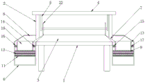
Fig. 2 is a side sectional view of the present invention.
Fig. 3 is an enlarged view of a portion a in fig. 2 according to the present invention.
In the figure, 1, a base; 2. a support frame; 3. trimming the edge; 4. a fixing plate; 5. a vertical plate; 6. a collection box; 7. a baffle; 8. a protective shell; 9. a filter plate; 10. a sloping plate; 11. a sponge plate; 12. a fine-pore filter plate; 13. a partition plate; 14. a screw rod; 15. an internally threaded tube; 16. a movable block; 17. a connecting plate; 18. a pressing plate; 19. a drive motor; 20. a drive sprocket; 21. a drive chain; 22. and a trimming mechanism.
Detailed Description
The technical solution of the present invention will be clearly and completely described below with reference to the specific embodiments. It is to be understood that the disclosed embodiments are merely exemplary of the invention, and are not intended to limit the invention to the precise embodiments disclosed. Based on the embodiments of the present invention, all other embodiments obtained by a person of ordinary skill in the art without creative efforts belong to the protection scope of the present invention.
Referring to figures 1-3 of the drawings,
example 1: the upper surface of the base 1 is fixedly connected with a supporting frame 2, the upper surface of the base 1 is fixedly connected with a trimming platform 3, the top of the supporting frame 2 is fixedly connected with a fixing plate 4, the lower surface of the fixing plate 4 is fixedly connected with a vertical plate 5, a trimming mechanism 22 is arranged inside the vertical plate 5, two sides of the base 1 are provided with collecting boxes 6, the outer surfaces of the collecting boxes 6 are fixedly connected with a guide plate 7, the upper surface of the collecting box 6 is fixedly connected with a protective shell 8, the inside of the collecting box 6 is fixedly connected with a filter plate 9, an inclined plate 10 is arranged inside the collecting box 6, a sponge plate 11 is fixedly connected between the filter plate 9 and the bottom wall of the collecting box 6, a pore filter plate 12 is fixedly connected between the filter plate 9 and the bottom wall of the collecting box 6, when the device is used, soaked liquid extruded from the edge of the wet towel can enter the inside of the collecting box 6 through the filter plate 9, then the magazines in the soaked liquid can be filtered under the action of the pore filter plate 12 and the sponge plate 11, then the soaked liquid can be discharged through a soaked liquid outlet, the effect of saving the soaked liquid can be achieved, the waste of the soaked liquid can be avoided, and the cost can be indirectly reduced;
example 2: the inside fixedly connected with division board 13 of collecting box 6, the inside of collecting box 6 has threaded spindle 14 that alternates to be provided with, the surface threaded connection of threaded spindle 14 has internal thread pipe 15, the surface fixedly connected with movable block 16 of internal thread pipe 15, the surface fixedly connected with connecting plate 17 of movable block 16, the surface fixedly connected with stripper plate 18 of connecting plate 17, through being provided with threaded spindle 14 and stripper plate 18, when the device uses, the operation through driving motor 19 can drive threaded spindle 14 to go on the well rotation, because threaded spindle 14 and internal thread pipe 15 threaded connection, and internal thread pipe 15 is connected with movable block 16, so when the threaded spindle 14 rotates, can drive movable block 16 to rotate along threaded spindle 14, because movable block 16 is connected with stripper plate 18 through connecting plate 17, so when movable block 16 moves along threaded spindle 14, can extrude the leftover bits of collection through stripper plate 18, and then can extrude the wet piece of wet tissue among the leftover bits of material and can collect through collecting box 6 the wet piece of soaking, the waste of wet liquid has been avoided, resources are saved.
The working principle is as follows: the safety of each structure of the device is checked before the device is used, the lead screw 14 and the extrusion plate 18 are arranged, when the device is used, the lead screw 14 can be driven to rotate in the middle through the operation of the driving motor 19, the lead screw 14 is in threaded connection with the internal thread pipe 15, the internal thread pipe 15 is connected with the movable block 16, when the lead screw 14 rotates, the movable block 16 can be driven to rotate along the lead screw 14, because the movable block 16 is connected with the extrusion plate 18 through the connecting plate 17, when the movable block 16 moves along the lead screw 14, collected rim charge can be extruded through the extrusion plate 18, further, the extruded wet tissue rim charge can be extruded, then the extruded wet tissue rim charge can be collected through the collecting box 6, the waste of wetting liquid is avoided, resources are saved, meanwhile, the filter plate 9 and the sponge plate 11 are utilized, when the device is used, the wetting liquid extruded in the rim charge can enter the collecting box 6 through the filter plate 9, then the wetting liquid in the wetting liquid can be collected under the effect of the wetting liquid under the effect of the sponge plate 12 and the sponge plate 11, the wetting liquid can be filtered, the waste of the wetting liquid can be further, the indirectly reduced by the filtering effect of the wetting liquid after the wetting liquid is achieved, and the wetting liquid is indirectly discharged.
It is noted that, herein, relational terms such as first and second, and the like may be used solely to distinguish one entity or action from another entity or action without necessarily requiring or implying any actual such relationship or order between such entities or actions. Moreover, the terms "comprises," "comprising," or any other variation thereof, are intended to cover a non-exclusive inclusion, such that a process, method, article, or apparatus that comprises a list of elements does not include only those elements but may include other elements not expressly listed or inherent to such process, method, article, or apparatus, and any standard components found in known art that may be commercially available or commercially available and may be readily customized based on the teachings of the specification and the drawings, and that the particular connection between the various components is by conventional means well known in the art, and that the machine, component, or apparatus is by model and circuit connection is by conventional means well known in the art, and will not be described in detail herein.
Although embodiments of the present invention have been shown and described, it will be appreciated by those skilled in the art that changes, modifications, substitutions and alterations can be made in these embodiments without departing from the principles and spirit of the invention, the scope of which is defined in the appended claims and their equivalents.
Claims (7)
1. The utility model provides an edge-trim collection device, includes base (1), its characterized in that: the upper surface of the base (1) is fixedly connected with a supporting frame (2), the upper surface of the base (1) is fixedly connected with a trimming table (3), the top of the supporting frame (2) is fixedly connected with a fixed plate (4), the lower surface of the fixed plate (4) is fixedly connected with a vertical plate (5), a trimming mechanism (22) is arranged inside the vertical plate (5), collecting boxes (6) are arranged on two sides of the base (1), a guide plate (7) is fixedly connected to the outer surfaces of the collecting boxes (6), a protective shell (8) is fixedly connected to the upper surface of the collecting boxes (6), a filter plate (9) is fixedly connected inside the collecting boxes (6), an inclined plate (10) is arranged inside the collecting boxes (6), a sponge plate (11) is fixedly connected between the filter plate (9) and the bottom wall of the collecting boxes (6), and a pore filter plate (12) is fixedly connected between the filter plate (9) and the bottom wall of the collecting boxes (6);
the collecting box is characterized in that a partition plate (13) is fixedly connected to the inside of the collecting box (6), a screw rod (14) is arranged inside the collecting box (6) in a penetrating mode, an internal thread pipe (15) is connected to the outer surface of the screw rod (14) in a threaded mode, a movable block (16) is fixedly connected to the outer surface of the internal thread pipe (15), a connecting plate (17) is fixedly connected to the outer surface of the movable block (16), and an extrusion plate (18) is fixedly connected to the outer surface of the connecting plate (17).
2. The scrap collecting apparatus according to claim 1, wherein: the lower fixed surface of base (1) is connected with four supporting legs, four the lower fixed surface of supporting leg is connected with the friction pad.
3. The scrap collecting apparatus according to claim 1, wherein: the outer surface of the trimming platform (3) is fixedly connected with the guide plate (7), one end of the guide plate (7) is arranged in an inclined mode, and the outer surface of the guide plate (7) is arranged in a lubricating mode.
4. The scrap collecting apparatus according to claim 1, wherein: the outer surfaces of the collecting box (6) and the protective shell (8) are coated with anti-corrosion coating, the thickness of the anti-corrosion coating is one millimeter, and one side of the collecting box (6) is provided with a soaking liquid outlet.
5. The scrap collecting apparatus according to claim 1, wherein: a discharge port is formed in one side of the collecting box (6), a sealing cover is arranged at the discharge port, the sealing cover is hinged to the discharge port, and a sealing ring is arranged on the outer surface of the sealing cover.
6. The scrap collecting apparatus according to claim 1, wherein: spacing holes are formed in the separating plate (13), and the connecting plate (17) moves in the spacing holes.
7. The scrap collecting apparatus according to claim 1, wherein: the inner wall swing joint of bearing frame and protecting crust (8) is passed through to the one end of lead screw (14), the outer fixed surface of protecting crust (8) is connected with the drive frame, the inside of drive frame is provided with driving motor (19), the output and lead screw (14) fixed connection of driving motor (19), the one end fixedly connected with drive sprocket (20) of lead screw (14), the surface transmission of drive sprocket (20) is connected with drive chain (21).
Priority Applications (1)
| Application Number | Priority Date | Filing Date | Title |
|---|---|---|---|
| CN202223192962.0U CN218748040U (en) | 2022-11-30 | 2022-11-30 | Rim charge collection device |
Applications Claiming Priority (1)
| Application Number | Priority Date | Filing Date | Title |
|---|---|---|---|
| CN202223192962.0U CN218748040U (en) | 2022-11-30 | 2022-11-30 | Rim charge collection device |
Publications (1)
| Publication Number | Publication Date |
|---|---|
| CN218748040U true CN218748040U (en) | 2023-03-28 |
Family
ID=85677386
Family Applications (1)
| Application Number | Title | Priority Date | Filing Date |
|---|---|---|---|
| CN202223192962.0U Active CN218748040U (en) | 2022-11-30 | 2022-11-30 | Rim charge collection device |
Country Status (1)
| Country | Link |
|---|---|
| CN (1) | CN218748040U (en) |
-
2022
- 2022-11-30 CN CN202223192962.0U patent/CN218748040U/en active Active
Similar Documents
| Publication | Publication Date | Title |
|---|---|---|
| CN108943447B (en) | Plate glass dust removal and crushing cutting machine | |
| CN211967727U (en) | Perforating equipment is used in processing of packing carton sponge | |
| CN218748040U (en) | Rim charge collection device | |
| CN113523891A (en) | Double-column plane milling machine convenient for collecting scraps | |
| CN110641063A (en) | Intelligent sorting and packaging device for solid wastes | |
| CN215999691U (en) | Numerical control machine tool with waste recovery structure | |
| CN112757033B (en) | Chip removal device of numerical control milling machine | |
| CN212981960U (en) | Transfer paper slitting and stripping machine | |
| CN212384133U (en) | Belt cleaning device is used in screw production | |
| CN214816989U (en) | Sealing gasket production cutting equipment with scrap collecting structure | |
| CN210731811U (en) | Aluminum product cutting garbage collection device | |
| CN112277363A (en) | Efficient kitchen waste treatment system and working method thereof | |
| CN112314678B (en) | Environment-friendly broiler chicken opsonized product processing equipment | |
| CN218428960U (en) | High-efficient bag sealer of furniture board | |
| CN219325027U (en) | Lathe processing sweeps recovery unit | |
| CN215429293U (en) | Carton cutting leftover bits recovery unit | |
| CN219665285U (en) | Numerical control sawing machine sweeps collection device | |
| CN220145383U (en) | Machining equipment belt cleaning device | |
| CN215749726U (en) | Dust collector between furniture processing vehicle | |
| CN219504280U (en) | Machining center waste recovery device | |
| CN218315467U (en) | Device of tailorring of makeup kit processing usefulness | |
| CN213970203U (en) | Lathe iron fillings collection device | |
| CN116141396B (en) | Production device for self-adhesive | |
| CN219503510U (en) | Structure is handled to metal stamping workpiece corner | |
| CN212981856U (en) | Special paper cuts stripper membrane cleaning device |
Legal Events
| Date | Code | Title | Description |
|---|---|---|---|
| GR01 | Patent grant | ||
| GR01 | Patent grant |