CN216854956U - Prosthetic heart valve - Google Patents
Prosthetic heart valve Download PDFInfo
- Publication number
- CN216854956U CN216854956U CN202121975838.4U CN202121975838U CN216854956U CN 216854956 U CN216854956 U CN 216854956U CN 202121975838 U CN202121975838 U CN 202121975838U CN 216854956 U CN216854956 U CN 216854956U
- Authority
- CN
- China
- Prior art keywords
- attachment member
- valve
- marker
- disposed
- heart valve
- Prior art date
- Legal status (The legal status is an assumption and is not a legal conclusion. Google has not performed a legal analysis and makes no representation as to the accuracy of the status listed.)
- Active
Links
- 210000003709 heart valve Anatomy 0.000 title claims abstract description 183
- 239000003550 marker Substances 0.000 claims abstract description 345
- 239000004744 fabric Substances 0.000 claims description 12
- 238000000034 method Methods 0.000 abstract description 123
- 238000003384 imaging method Methods 0.000 description 141
- 238000002788 crimping Methods 0.000 description 128
- 230000013011 mating Effects 0.000 description 87
- 238000002513 implantation Methods 0.000 description 84
- 230000008878 coupling Effects 0.000 description 49
- 238000010168 coupling process Methods 0.000 description 49
- 238000005859 coupling reaction Methods 0.000 description 49
- 239000007943 implant Substances 0.000 description 37
- 239000012530 fluid Substances 0.000 description 35
- 210000004351 coronary vessel Anatomy 0.000 description 34
- 239000000463 material Substances 0.000 description 30
- 210000002216 heart Anatomy 0.000 description 24
- 238000007373 indentation Methods 0.000 description 20
- 230000007246 mechanism Effects 0.000 description 19
- 210000001765 aortic valve Anatomy 0.000 description 18
- 238000003825 pressing Methods 0.000 description 18
- 230000017531 blood circulation Effects 0.000 description 15
- 238000002594 fluoroscopy Methods 0.000 description 12
- 210000003484 anatomy Anatomy 0.000 description 10
- 210000000709 aorta Anatomy 0.000 description 10
- 238000003780 insertion Methods 0.000 description 10
- 230000037431 insertion Effects 0.000 description 10
- 238000007789 sealing Methods 0.000 description 10
- 210000001519 tissue Anatomy 0.000 description 10
- 229910045601 alloy Inorganic materials 0.000 description 9
- 239000000956 alloy Substances 0.000 description 9
- 238000002059 diagnostic imaging Methods 0.000 description 9
- 238000010586 diagram Methods 0.000 description 9
- 210000000591 tricuspid valve Anatomy 0.000 description 9
- 210000005166 vasculature Anatomy 0.000 description 9
- 230000000712 assembly Effects 0.000 description 8
- 238000000429 assembly Methods 0.000 description 8
- 238000007872 degassing Methods 0.000 description 8
- 230000004323 axial length Effects 0.000 description 7
- 238000005516 engineering process Methods 0.000 description 6
- 230000008569 process Effects 0.000 description 6
- 229910052715 tantalum Inorganic materials 0.000 description 6
- GUVRBAGPIYLISA-UHFFFAOYSA-N tantalum atom Chemical compound [Ta] GUVRBAGPIYLISA-UHFFFAOYSA-N 0.000 description 6
- 230000008901 benefit Effects 0.000 description 5
- 230000006835 compression Effects 0.000 description 5
- 238000007906 compression Methods 0.000 description 5
- 230000007423 decrease Effects 0.000 description 5
- 238000002955 isolation Methods 0.000 description 5
- 230000002829 reductive effect Effects 0.000 description 5
- 230000004044 response Effects 0.000 description 5
- 229910000566 Platinum-iridium alloy Inorganic materials 0.000 description 4
- 239000000853 adhesive Substances 0.000 description 4
- 230000001070 adhesive effect Effects 0.000 description 4
- 230000006870 function Effects 0.000 description 4
- 230000036961 partial effect Effects 0.000 description 4
- HWLDNSXPUQTBOD-UHFFFAOYSA-N platinum-iridium alloy Chemical class [Ir].[Pt] HWLDNSXPUQTBOD-UHFFFAOYSA-N 0.000 description 4
- 230000000717 retained effect Effects 0.000 description 4
- 239000011343 solid material Substances 0.000 description 4
- 238000003466 welding Methods 0.000 description 4
- 230000008859 change Effects 0.000 description 3
- 230000000670 limiting effect Effects 0.000 description 3
- 229910001000 nickel titanium Inorganic materials 0.000 description 3
- 238000004806 packaging method and process Methods 0.000 description 3
- 239000000126 substance Chemical group 0.000 description 3
- PXHVJJICTQNCMI-UHFFFAOYSA-N Nickel Chemical compound [Ni] PXHVJJICTQNCMI-UHFFFAOYSA-N 0.000 description 2
- TZCXTZWJZNENPQ-UHFFFAOYSA-L barium sulfate Chemical compound [Ba+2].[O-]S([O-])(=O)=O TZCXTZWJZNENPQ-UHFFFAOYSA-L 0.000 description 2
- 239000002775 capsule Substances 0.000 description 2
- 230000015556 catabolic process Effects 0.000 description 2
- 238000006731 degradation reaction Methods 0.000 description 2
- 238000013461 design Methods 0.000 description 2
- 201000010099 disease Diseases 0.000 description 2
- 208000037265 diseases, disorders, signs and symptoms Diseases 0.000 description 2
- 229920005570 flexible polymer Polymers 0.000 description 2
- 230000014759 maintenance of location Effects 0.000 description 2
- 229910052751 metal Inorganic materials 0.000 description 2
- 239000002184 metal Substances 0.000 description 2
- 239000005020 polyethylene terephthalate Substances 0.000 description 2
- 229920000139 polyethylene terephthalate Polymers 0.000 description 2
- 229920000642 polymer Polymers 0.000 description 2
- 239000010935 stainless steel Substances 0.000 description 2
- 229910001220 stainless steel Inorganic materials 0.000 description 2
- 238000001356 surgical procedure Methods 0.000 description 2
- 229920002994 synthetic fiber Polymers 0.000 description 2
- 241000283690 Bos taurus Species 0.000 description 1
- OYPRJOBELJOOCE-UHFFFAOYSA-N Calcium Chemical compound [Ca] OYPRJOBELJOOCE-UHFFFAOYSA-N 0.000 description 1
- VYZAMTAEIAYCRO-UHFFFAOYSA-N Chromium Chemical compound [Cr] VYZAMTAEIAYCRO-UHFFFAOYSA-N 0.000 description 1
- 229910000684 Cobalt-chrome Inorganic materials 0.000 description 1
- ZOKXTWBITQBERF-UHFFFAOYSA-N Molybdenum Chemical compound [Mo] ZOKXTWBITQBERF-UHFFFAOYSA-N 0.000 description 1
- 101150110932 US19 gene Proteins 0.000 description 1
- WAIPAZQMEIHHTJ-UHFFFAOYSA-N [Cr].[Co] Chemical compound [Cr].[Co] WAIPAZQMEIHHTJ-UHFFFAOYSA-N 0.000 description 1
- HZEWFHLRYVTOIW-UHFFFAOYSA-N [Ti].[Ni] Chemical compound [Ti].[Ni] HZEWFHLRYVTOIW-UHFFFAOYSA-N 0.000 description 1
- 230000002159 abnormal effect Effects 0.000 description 1
- 230000002411 adverse Effects 0.000 description 1
- 229910052797 bismuth Inorganic materials 0.000 description 1
- JCXGWMGPZLAOME-UHFFFAOYSA-N bismuth atom Chemical compound [Bi] JCXGWMGPZLAOME-UHFFFAOYSA-N 0.000 description 1
- 239000008280 blood Substances 0.000 description 1
- 210000004369 blood Anatomy 0.000 description 1
- 210000004204 blood vessel Anatomy 0.000 description 1
- 229910052791 calcium Inorganic materials 0.000 description 1
- 239000011575 calcium Substances 0.000 description 1
- 229910052804 chromium Inorganic materials 0.000 description 1
- 239000011651 chromium Substances 0.000 description 1
- 239000000788 chromium alloy Substances 0.000 description 1
- PRQRQKBNBXPISG-UHFFFAOYSA-N chromium cobalt molybdenum nickel Chemical compound [Cr].[Co].[Ni].[Mo] PRQRQKBNBXPISG-UHFFFAOYSA-N 0.000 description 1
- SZMZREIADCOWQA-UHFFFAOYSA-N chromium cobalt nickel Chemical compound [Cr].[Co].[Ni] SZMZREIADCOWQA-UHFFFAOYSA-N 0.000 description 1
- 229910017052 cobalt Inorganic materials 0.000 description 1
- 239000010941 cobalt Substances 0.000 description 1
- GUTLYIVDDKVIGB-UHFFFAOYSA-N cobalt atom Chemical compound [Co] GUTLYIVDDKVIGB-UHFFFAOYSA-N 0.000 description 1
- 239000010952 cobalt-chrome Substances 0.000 description 1
- 238000004891 communication Methods 0.000 description 1
- 230000000295 complement effect Effects 0.000 description 1
- 150000001875 compounds Chemical group 0.000 description 1
- 230000001010 compromised effect Effects 0.000 description 1
- 238000005520 cutting process Methods 0.000 description 1
- 229910003460 diamond Inorganic materials 0.000 description 1
- 239000010432 diamond Substances 0.000 description 1
- 238000002224 dissection Methods 0.000 description 1
- 210000005069 ears Anatomy 0.000 description 1
- 238000002592 echocardiography Methods 0.000 description 1
- 230000002526 effect on cardiovascular system Effects 0.000 description 1
- 238000005530 etching Methods 0.000 description 1
- 210000001105 femoral artery Anatomy 0.000 description 1
- PCHJSUWPFVWCPO-UHFFFAOYSA-N gold Chemical compound [Au] PCHJSUWPFVWCPO-UHFFFAOYSA-N 0.000 description 1
- 229910052737 gold Inorganic materials 0.000 description 1
- 239000010931 gold Substances 0.000 description 1
- 238000002347 injection Methods 0.000 description 1
- 239000007924 injection Substances 0.000 description 1
- 238000013152 interventional procedure Methods 0.000 description 1
- PNDPGZBMCMUPRI-UHFFFAOYSA-N iodine Chemical compound II PNDPGZBMCMUPRI-UHFFFAOYSA-N 0.000 description 1
- 230000007257 malfunction Effects 0.000 description 1
- 238000004519 manufacturing process Methods 0.000 description 1
- 239000007769 metal material Substances 0.000 description 1
- 210000004115 mitral valve Anatomy 0.000 description 1
- 238000012986 modification Methods 0.000 description 1
- 230000004048 modification Effects 0.000 description 1
- 229910052750 molybdenum Inorganic materials 0.000 description 1
- 239000011733 molybdenum Substances 0.000 description 1
- 210000003205 muscle Anatomy 0.000 description 1
- 210000004165 myocardium Anatomy 0.000 description 1
- 229910052759 nickel Inorganic materials 0.000 description 1
- HLXZNVUGXRDIFK-UHFFFAOYSA-N nickel titanium Chemical compound [Ti].[Ti].[Ti].[Ti].[Ti].[Ti].[Ti].[Ti].[Ti].[Ti].[Ti].[Ni].[Ni].[Ni].[Ni].[Ni].[Ni].[Ni].[Ni].[Ni].[Ni].[Ni].[Ni].[Ni].[Ni] HLXZNVUGXRDIFK-UHFFFAOYSA-N 0.000 description 1
- 210000000056 organ Anatomy 0.000 description 1
- 239000005022 packaging material Substances 0.000 description 1
- -1 polyethylene terephthalate Polymers 0.000 description 1
- 230000002685 pulmonary effect Effects 0.000 description 1
- 210000003102 pulmonary valve Anatomy 0.000 description 1
- 230000008707 rearrangement Effects 0.000 description 1
- 230000003014 reinforcing effect Effects 0.000 description 1
- 230000008439 repair process Effects 0.000 description 1
- 239000012858 resilient material Substances 0.000 description 1
- 125000006850 spacer group Chemical group 0.000 description 1
- 230000002966 stenotic effect Effects 0.000 description 1
- 238000003860 storage Methods 0.000 description 1
- 239000004094 surface-active agent Substances 0.000 description 1
- 238000012360 testing method Methods 0.000 description 1
- 238000002604 ultrasonography Methods 0.000 description 1
- 230000000007 visual effect Effects 0.000 description 1
- 239000000602 vitallium Substances 0.000 description 1
Images


Classifications
-
- A—HUMAN NECESSITIES
- A61—MEDICAL OR VETERINARY SCIENCE; HYGIENE
- A61F—FILTERS IMPLANTABLE INTO BLOOD VESSELS; PROSTHESES; DEVICES PROVIDING PATENCY TO, OR PREVENTING COLLAPSING OF, TUBULAR STRUCTURES OF THE BODY, e.g. STENTS; ORTHOPAEDIC, NURSING OR CONTRACEPTIVE DEVICES; FOMENTATION; TREATMENT OR PROTECTION OF EYES OR EARS; BANDAGES, DRESSINGS OR ABSORBENT PADS; FIRST-AID KITS
- A61F2/00—Filters implantable into blood vessels; Prostheses, i.e. artificial substitutes or replacements for parts of the body; Appliances for connecting them with the body; Devices providing patency to, or preventing collapsing of, tubular structures of the body, e.g. stents
- A61F2/02—Prostheses implantable into the body
- A61F2/24—Heart valves ; Vascular valves, e.g. venous valves; Heart implants, e.g. passive devices for improving the function of the native valve or the heart muscle; Transmyocardial revascularisation [TMR] devices; Valves implantable in the body
- A61F2/2427—Devices for manipulating or deploying heart valves during implantation
- A61F2/243—Deployment by mechanical expansion
- A61F2/2433—Deployment by mechanical expansion using balloon catheter
-
- A—HUMAN NECESSITIES
- A61—MEDICAL OR VETERINARY SCIENCE; HYGIENE
- A61B—DIAGNOSIS; SURGERY; IDENTIFICATION
- A61B50/00—Containers, covers, furniture or holders specially adapted for surgical or diagnostic appliances or instruments, e.g. sterile covers
- A61B50/30—Containers specially adapted for packaging, protecting, dispensing, collecting or disposing of surgical or diagnostic appliances or instruments
-
- A—HUMAN NECESSITIES
- A61—MEDICAL OR VETERINARY SCIENCE; HYGIENE
- A61F—FILTERS IMPLANTABLE INTO BLOOD VESSELS; PROSTHESES; DEVICES PROVIDING PATENCY TO, OR PREVENTING COLLAPSING OF, TUBULAR STRUCTURES OF THE BODY, e.g. STENTS; ORTHOPAEDIC, NURSING OR CONTRACEPTIVE DEVICES; FOMENTATION; TREATMENT OR PROTECTION OF EYES OR EARS; BANDAGES, DRESSINGS OR ABSORBENT PADS; FIRST-AID KITS
- A61F2/00—Filters implantable into blood vessels; Prostheses, i.e. artificial substitutes or replacements for parts of the body; Appliances for connecting them with the body; Devices providing patency to, or preventing collapsing of, tubular structures of the body, e.g. stents
- A61F2/02—Prostheses implantable into the body
- A61F2/24—Heart valves ; Vascular valves, e.g. venous valves; Heart implants, e.g. passive devices for improving the function of the native valve or the heart muscle; Transmyocardial revascularisation [TMR] devices; Valves implantable in the body
- A61F2/2427—Devices for manipulating or deploying heart valves during implantation
- A61F2/2436—Deployment by retracting a sheath
-
- A—HUMAN NECESSITIES
- A61—MEDICAL OR VETERINARY SCIENCE; HYGIENE
- A61F—FILTERS IMPLANTABLE INTO BLOOD VESSELS; PROSTHESES; DEVICES PROVIDING PATENCY TO, OR PREVENTING COLLAPSING OF, TUBULAR STRUCTURES OF THE BODY, e.g. STENTS; ORTHOPAEDIC, NURSING OR CONTRACEPTIVE DEVICES; FOMENTATION; TREATMENT OR PROTECTION OF EYES OR EARS; BANDAGES, DRESSINGS OR ABSORBENT PADS; FIRST-AID KITS
- A61F2/00—Filters implantable into blood vessels; Prostheses, i.e. artificial substitutes or replacements for parts of the body; Appliances for connecting them with the body; Devices providing patency to, or preventing collapsing of, tubular structures of the body, e.g. stents
- A61F2/02—Prostheses implantable into the body
- A61F2/24—Heart valves ; Vascular valves, e.g. venous valves; Heart implants, e.g. passive devices for improving the function of the native valve or the heart muscle; Transmyocardial revascularisation [TMR] devices; Valves implantable in the body
- A61F2/2442—Annuloplasty rings or inserts for correcting the valve shape; Implants for improving the function of a native heart valve
-
- A—HUMAN NECESSITIES
- A61—MEDICAL OR VETERINARY SCIENCE; HYGIENE
- A61M—DEVICES FOR INTRODUCING MEDIA INTO, OR ONTO, THE BODY; DEVICES FOR TRANSDUCING BODY MEDIA OR FOR TAKING MEDIA FROM THE BODY; DEVICES FOR PRODUCING OR ENDING SLEEP OR STUPOR
- A61M25/00—Catheters; Hollow probes
- A61M25/10—Balloon catheters
-
- A—HUMAN NECESSITIES
- A61—MEDICAL OR VETERINARY SCIENCE; HYGIENE
- A61F—FILTERS IMPLANTABLE INTO BLOOD VESSELS; PROSTHESES; DEVICES PROVIDING PATENCY TO, OR PREVENTING COLLAPSING OF, TUBULAR STRUCTURES OF THE BODY, e.g. STENTS; ORTHOPAEDIC, NURSING OR CONTRACEPTIVE DEVICES; FOMENTATION; TREATMENT OR PROTECTION OF EYES OR EARS; BANDAGES, DRESSINGS OR ABSORBENT PADS; FIRST-AID KITS
- A61F2/00—Filters implantable into blood vessels; Prostheses, i.e. artificial substitutes or replacements for parts of the body; Appliances for connecting them with the body; Devices providing patency to, or preventing collapsing of, tubular structures of the body, e.g. stents
- A61F2/02—Prostheses implantable into the body
- A61F2/24—Heart valves ; Vascular valves, e.g. venous valves; Heart implants, e.g. passive devices for improving the function of the native valve or the heart muscle; Transmyocardial revascularisation [TMR] devices; Valves implantable in the body
- A61F2/2412—Heart valves ; Vascular valves, e.g. venous valves; Heart implants, e.g. passive devices for improving the function of the native valve or the heart muscle; Transmyocardial revascularisation [TMR] devices; Valves implantable in the body with soft flexible valve members, e.g. tissue valves shaped like natural valves
- A61F2/2418—Scaffolds therefor, e.g. support stents
-
- A—HUMAN NECESSITIES
- A61—MEDICAL OR VETERINARY SCIENCE; HYGIENE
- A61F—FILTERS IMPLANTABLE INTO BLOOD VESSELS; PROSTHESES; DEVICES PROVIDING PATENCY TO, OR PREVENTING COLLAPSING OF, TUBULAR STRUCTURES OF THE BODY, e.g. STENTS; ORTHOPAEDIC, NURSING OR CONTRACEPTIVE DEVICES; FOMENTATION; TREATMENT OR PROTECTION OF EYES OR EARS; BANDAGES, DRESSINGS OR ABSORBENT PADS; FIRST-AID KITS
- A61F2/00—Filters implantable into blood vessels; Prostheses, i.e. artificial substitutes or replacements for parts of the body; Appliances for connecting them with the body; Devices providing patency to, or preventing collapsing of, tubular structures of the body, e.g. stents
- A61F2/95—Instruments specially adapted for placement or removal of stents or stent-grafts
- A61F2/9517—Instruments specially adapted for placement or removal of stents or stent-grafts handle assemblies therefor
-
- A—HUMAN NECESSITIES
- A61—MEDICAL OR VETERINARY SCIENCE; HYGIENE
- A61F—FILTERS IMPLANTABLE INTO BLOOD VESSELS; PROSTHESES; DEVICES PROVIDING PATENCY TO, OR PREVENTING COLLAPSING OF, TUBULAR STRUCTURES OF THE BODY, e.g. STENTS; ORTHOPAEDIC, NURSING OR CONTRACEPTIVE DEVICES; FOMENTATION; TREATMENT OR PROTECTION OF EYES OR EARS; BANDAGES, DRESSINGS OR ABSORBENT PADS; FIRST-AID KITS
- A61F2/00—Filters implantable into blood vessels; Prostheses, i.e. artificial substitutes or replacements for parts of the body; Appliances for connecting them with the body; Devices providing patency to, or preventing collapsing of, tubular structures of the body, e.g. stents
- A61F2/82—Devices providing patency to, or preventing collapsing of, tubular structures of the body, e.g. stents
- A61F2002/825—Devices providing patency to, or preventing collapsing of, tubular structures of the body, e.g. stents having longitudinal struts
-
- A—HUMAN NECESSITIES
- A61—MEDICAL OR VETERINARY SCIENCE; HYGIENE
- A61F—FILTERS IMPLANTABLE INTO BLOOD VESSELS; PROSTHESES; DEVICES PROVIDING PATENCY TO, OR PREVENTING COLLAPSING OF, TUBULAR STRUCTURES OF THE BODY, e.g. STENTS; ORTHOPAEDIC, NURSING OR CONTRACEPTIVE DEVICES; FOMENTATION; TREATMENT OR PROTECTION OF EYES OR EARS; BANDAGES, DRESSINGS OR ABSORBENT PADS; FIRST-AID KITS
- A61F2/00—Filters implantable into blood vessels; Prostheses, i.e. artificial substitutes or replacements for parts of the body; Appliances for connecting them with the body; Devices providing patency to, or preventing collapsing of, tubular structures of the body, e.g. stents
- A61F2/95—Instruments specially adapted for placement or removal of stents or stent-grafts
- A61F2/958—Inflatable balloons for placing stents or stent-grafts
- A61F2002/9583—Means for holding the stent on the balloon, e.g. using protrusions, adhesives or an outer sleeve
-
- A—HUMAN NECESSITIES
- A61—MEDICAL OR VETERINARY SCIENCE; HYGIENE
- A61F—FILTERS IMPLANTABLE INTO BLOOD VESSELS; PROSTHESES; DEVICES PROVIDING PATENCY TO, OR PREVENTING COLLAPSING OF, TUBULAR STRUCTURES OF THE BODY, e.g. STENTS; ORTHOPAEDIC, NURSING OR CONTRACEPTIVE DEVICES; FOMENTATION; TREATMENT OR PROTECTION OF EYES OR EARS; BANDAGES, DRESSINGS OR ABSORBENT PADS; FIRST-AID KITS
- A61F2/00—Filters implantable into blood vessels; Prostheses, i.e. artificial substitutes or replacements for parts of the body; Appliances for connecting them with the body; Devices providing patency to, or preventing collapsing of, tubular structures of the body, e.g. stents
- A61F2/95—Instruments specially adapted for placement or removal of stents or stent-grafts
- A61F2/962—Instruments specially adapted for placement or removal of stents or stent-grafts having an outer sleeve
- A61F2/966—Instruments specially adapted for placement or removal of stents or stent-grafts having an outer sleeve with relative longitudinal movement between outer sleeve and prosthesis, e.g. using a push rod
- A61F2002/9665—Instruments specially adapted for placement or removal of stents or stent-grafts having an outer sleeve with relative longitudinal movement between outer sleeve and prosthesis, e.g. using a push rod with additional retaining means
-
- A—HUMAN NECESSITIES
- A61—MEDICAL OR VETERINARY SCIENCE; HYGIENE
- A61F—FILTERS IMPLANTABLE INTO BLOOD VESSELS; PROSTHESES; DEVICES PROVIDING PATENCY TO, OR PREVENTING COLLAPSING OF, TUBULAR STRUCTURES OF THE BODY, e.g. STENTS; ORTHOPAEDIC, NURSING OR CONTRACEPTIVE DEVICES; FOMENTATION; TREATMENT OR PROTECTION OF EYES OR EARS; BANDAGES, DRESSINGS OR ABSORBENT PADS; FIRST-AID KITS
- A61F2220/00—Fixations or connections for prostheses classified in groups A61F2/00 - A61F2/26 or A61F2/82 or A61F9/00 or A61F11/00 or subgroups thereof
- A61F2220/0025—Connections or couplings between prosthetic parts, e.g. between modular parts; Connecting elements
- A61F2220/0075—Connections or couplings between prosthetic parts, e.g. between modular parts; Connecting elements sutured, ligatured or stitched, retained or tied with a rope, string, thread, wire or cable
-
- A—HUMAN NECESSITIES
- A61—MEDICAL OR VETERINARY SCIENCE; HYGIENE
- A61F—FILTERS IMPLANTABLE INTO BLOOD VESSELS; PROSTHESES; DEVICES PROVIDING PATENCY TO, OR PREVENTING COLLAPSING OF, TUBULAR STRUCTURES OF THE BODY, e.g. STENTS; ORTHOPAEDIC, NURSING OR CONTRACEPTIVE DEVICES; FOMENTATION; TREATMENT OR PROTECTION OF EYES OR EARS; BANDAGES, DRESSINGS OR ABSORBENT PADS; FIRST-AID KITS
- A61F2230/00—Geometry of prostheses classified in groups A61F2/00 - A61F2/26 or A61F2/82 or A61F9/00 or A61F11/00 or subgroups thereof
- A61F2230/0002—Two-dimensional shapes, e.g. cross-sections
- A61F2230/0028—Shapes in the form of latin or greek characters
- A61F2230/0039—H-shaped
-
- A—HUMAN NECESSITIES
- A61—MEDICAL OR VETERINARY SCIENCE; HYGIENE
- A61F—FILTERS IMPLANTABLE INTO BLOOD VESSELS; PROSTHESES; DEVICES PROVIDING PATENCY TO, OR PREVENTING COLLAPSING OF, TUBULAR STRUCTURES OF THE BODY, e.g. STENTS; ORTHOPAEDIC, NURSING OR CONTRACEPTIVE DEVICES; FOMENTATION; TREATMENT OR PROTECTION OF EYES OR EARS; BANDAGES, DRESSINGS OR ABSORBENT PADS; FIRST-AID KITS
- A61F2230/00—Geometry of prostheses classified in groups A61F2/00 - A61F2/26 or A61F2/82 or A61F9/00 or A61F11/00 or subgroups thereof
- A61F2230/0002—Two-dimensional shapes, e.g. cross-sections
- A61F2230/0028—Shapes in the form of latin or greek characters
- A61F2230/0054—V-shaped
-
- A—HUMAN NECESSITIES
- A61—MEDICAL OR VETERINARY SCIENCE; HYGIENE
- A61F—FILTERS IMPLANTABLE INTO BLOOD VESSELS; PROSTHESES; DEVICES PROVIDING PATENCY TO, OR PREVENTING COLLAPSING OF, TUBULAR STRUCTURES OF THE BODY, e.g. STENTS; ORTHOPAEDIC, NURSING OR CONTRACEPTIVE DEVICES; FOMENTATION; TREATMENT OR PROTECTION OF EYES OR EARS; BANDAGES, DRESSINGS OR ABSORBENT PADS; FIRST-AID KITS
- A61F2250/00—Special features of prostheses classified in groups A61F2/00 - A61F2/26 or A61F2/82 or A61F9/00 or A61F11/00 or subgroups thereof
- A61F2250/0014—Special features of prostheses classified in groups A61F2/00 - A61F2/26 or A61F2/82 or A61F9/00 or A61F11/00 or subgroups thereof having different values of a given property or geometrical feature, e.g. mechanical property or material property, at different locations within the same prosthesis
- A61F2250/0039—Special features of prostheses classified in groups A61F2/00 - A61F2/26 or A61F2/82 or A61F9/00 or A61F11/00 or subgroups thereof having different values of a given property or geometrical feature, e.g. mechanical property or material property, at different locations within the same prosthesis differing in diameter
-
- A—HUMAN NECESSITIES
- A61—MEDICAL OR VETERINARY SCIENCE; HYGIENE
- A61F—FILTERS IMPLANTABLE INTO BLOOD VESSELS; PROSTHESES; DEVICES PROVIDING PATENCY TO, OR PREVENTING COLLAPSING OF, TUBULAR STRUCTURES OF THE BODY, e.g. STENTS; ORTHOPAEDIC, NURSING OR CONTRACEPTIVE DEVICES; FOMENTATION; TREATMENT OR PROTECTION OF EYES OR EARS; BANDAGES, DRESSINGS OR ABSORBENT PADS; FIRST-AID KITS
- A61F2250/00—Special features of prostheses classified in groups A61F2/00 - A61F2/26 or A61F2/82 or A61F9/00 or A61F11/00 or subgroups thereof
- A61F2250/0058—Additional features; Implant or prostheses properties not otherwise provided for
- A61F2250/0096—Markers and sensors for detecting a position or changes of a position of an implant, e.g. RF sensors, ultrasound markers
- A61F2250/0098—Markers and sensors for detecting a position or changes of a position of an implant, e.g. RF sensors, ultrasound markers radio-opaque, e.g. radio-opaque markers
Landscapes
- Health & Medical Sciences (AREA)
- Cardiology (AREA)
- Engineering & Computer Science (AREA)
- Biomedical Technology (AREA)
- Life Sciences & Earth Sciences (AREA)
- Heart & Thoracic Surgery (AREA)
- Veterinary Medicine (AREA)
- Animal Behavior & Ethology (AREA)
- General Health & Medical Sciences (AREA)
- Public Health (AREA)
- Vascular Medicine (AREA)
- Transplantation (AREA)
- Oral & Maxillofacial Surgery (AREA)
- Mechanical Engineering (AREA)
- Surgery (AREA)
- Medical Informatics (AREA)
- Molecular Biology (AREA)
- Child & Adolescent Psychology (AREA)
- Biophysics (AREA)
- Pulmonology (AREA)
- Anesthesiology (AREA)
- Hematology (AREA)
- Nuclear Medicine, Radiotherapy & Molecular Imaging (AREA)
- Prostheses (AREA)
- Media Introduction/Drainage Providing Device (AREA)
Abstract
The present application relates to prosthetic heart valves. Methods and systems are disclosed for attaching a radiopaque marker to a prosthetic heart valve to indicate the location of a commissure of the prosthetic heart valve, wherein the prosthetic heart valve can include a frame comprising a plurality of struts, a plurality of leaflets, at least one commissure, and the radiopaque marker.
Description
Cross Reference to Related Applications
This application claims the benefit of U.S. provisional patent application No. 63/138,890 filed on day 1, 19, 2021 and also claims the benefit of U.S. provisional patent application No. 63/069,567 filed on day 24, 8, 2020, which is incorporated herein by reference in its entirety.
Technical Field
The present disclosure relates to prosthetic heart valves and markers for prosthetic heart valves configured to indicate the location of commissures of the prosthetic heart valve.
Background
The human heart is afflicted with various valvular diseases. These valve diseases can lead to severe malfunction of the heart, eventually requiring repair of the native valve or replacement of the native valve with a prosthetic valve. There are many known prosthetic devices (e.g., stents) and prosthetic valves, and many known methods of implanting these devices and valves into the human body. Percutaneous and minimally invasive surgical methods are used in a variety of procedures to deliver prosthetic medical devices to locations within the body that are not readily accessible through surgery or are desired to be accessed without surgery. In one particular example, the prosthetic heart valve can be mounted on the distal end of a delivery device in a crimped state and advanced through the patient's vasculature (e.g., through the femoral artery and aorta) until the prosthetic valve reaches an implantation site in the heart. The prosthetic valve is then expanded to its functional size, for example, by inflating a balloon on which the prosthetic valve is mounted.
When the prosthetic valve is deployed at the native valve (e.g., by inflating a balloon of the delivery device), the radially-expanded prosthetic valve is deployed in a random radial orientation relative to the native valve. Thus, in some embodiments, one of the commissures of the prosthetic valve can be disposed anterior (e.g., adjacent) to a coronary ostium of the aorta. Such an arrangement may reduce coronary access (e.g., blood flow from the aorta to the coronary arteries) and/or create difficulties during future cardiovascular interventions aimed at maintaining or increasing coronary access. In addition, after implantation of the prosthetic heart valve, it may be desirable to confirm the location of the commissures of the prosthetic heart valve relative to the commissures of the native heart valve.
Accordingly, there is a need for improved prosthetic heart valve configurations that allow for identification of the location of one or more commissures of the prosthetic heart valve during an implantation procedure and/or after implantation at the native heart valve.
SUMMERY OF THE UTILITY MODEL
Embodiments of prosthetic heart valves including one or more radiopaque markers positioned on or near the commissures of the prosthetic heart valve are described herein. Thus, during a valve implantation procedure and/or after implantation of the prosthetic heart valve at the native heart valve, the location of selected commissures of the prosthetic valve can be identified by medical imaging.
In one representative embodiment, a prosthetic heart valve includes a frame including a plurality of struts forming a plurality of cells of the frame disposed between an inflow end and an outflow end of the frame; a plurality of leaflets disposed within the frame; at least one commissure comprising an attachment member and commissure lugs of two adjacent leaflets, the attachment member being arranged across a selected cell of the plurality of cells of the frame and attached to struts of the frame forming the selected cell, and the commissure lugs of the two adjacent leaflets being coupled to the attachment member; and a radiopaque marker disposed on the attachment member of the commissure, the marker configured to indicate a location of the commissure of the prosthetic heart valve.
In another representative embodiment, a prosthetic heart valve includes a frame including a plurality of struts forming a plurality of cells of the frame disposed between an inflow end and an outflow end of the frame; a plurality of leaflets disposed within the frame; at least one commissure comprising a first attachment member and commissure lugs of two adjacent leaflets, the first attachment member being arranged across a selected cell of the plurality of cells of the frame and attached to struts of the frame forming the selected cell, and the commissure lugs of the two adjacent leaflets being coupled to the first attachment member; and a radiopaque marker attached to a second attachment member disposed across the selected cell and attached to the strut forming the selected cell, the second attachment member disposed external to the first attachment member relative to a central longitudinal axis of the frame. The marker is configured to indicate a location of the commissures of the prosthetic heart valve.
In another representative embodiment, a prosthetic heart valve includes a frame comprising a plurality of struts forming a plurality of cells of the frame disposed between an inflow end and an outflow end of the frame; a plurality of leaflets disposed within the frame; at least one commissure comprising commissure lugs of two adjacent leaflets of the plurality of leaflets connected to each other, the at least one commissure being secured to posts of the frame forming a selected cell of the plurality of cells; and a radiopaque marker attached to an attachment member disposed across the selected cell and attached to the strut forming the selected cell. The marker is configured to indicate a location of the commissures of the prosthetic heart valve.
The above and other objects, features and advantages of the disclosed technology will become more apparent from the following detailed description, which proceeds with reference to the accompanying drawings.
Drawings
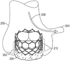
FIG. 1 is a perspective view of a prosthetic heart valve according to one embodiment.
Fig. 2A is a perspective view of a prosthetic heart valve according to another embodiment.
Fig. 2B is a perspective view of the prosthetic valve of fig. 2A, with components on the outside of the frame shown in transparent lines for illustration purposes.
Fig. 3 is a perspective view of a delivery apparatus for a prosthetic heart valve according to one embodiment.
Fig. 4 is a schematic diagram of an exemplary heart showing the location of coronary arteries relative to an aortic valve.
Fig. 5A illustrates an exemplary positioning of a prosthetic valve in an aortic valve relative to a coronary artery.
Fig. 5B illustrates another exemplary positioning of a prosthetic valve in an aortic valve relative to a coronary artery, wherein the prosthetic valve at least partially inhibits blood flow to the coronary artery.
Fig. 6A is a cross-sectional view of an aortic valve illustrating a first positioning of the prosthetic valve within the aortic valve in which commissures of the prosthetic valve at least partially block one or more openings to the coronary arteries.
Fig. 6B is a cross-sectional view of the aortic valve illustrating a second positioning of the prosthetic valve within the aortic valve with the commissures of the prosthetic valve circumferentially aligned with the native commissures of the aortic valve to maintain access to the coronary arteries.
Fig. 7 illustrates a leaflet cutting procedure in which when the prosthetic heart valve is implanted within an aortic valve, the leaflets of the native aortic valve can be split at the location of the entrance to the coronary arteries to enable increased blood flow into the coronary arteries.
Fig. 8A illustrates an example prosthetic heart valve and an example of how splitting native leaflets around the prosthetic heart valve at a region of a frame of the prosthetic heart valve between two adjacent commissures results in an open cell anterior to an entrance to a coronary artery.
Fig. 8B illustrates the exemplary prosthetic heart valve of fig. 8A and how splitting the native leaflets in a region of the frame of the prosthetic heart valve that includes the commissures does not result in the open cells being disposed anterior of the entry to the coronary arteries.
Fig. 9 is a side view of an embodiment of a delivery apparatus configured to deliver and implant a radially expandable prosthetic heart valve at an implantation site.
Fig. 10 is a cross-sectional side view of the distal portion of the delivery device of fig. 9.
Fig. 11 is a side view of the distal end portion of the delivery apparatus of fig. 9, illustrating a distal tip portion of the outer shaft of the delivery apparatus.
Fig. 12 is a schematic view of an embodiment of an intermediate shaft of the delivery apparatus of fig. 9.
Fig. 13 is a cross-sectional side view of a detail of the coaxial shaft of the delivery apparatus of fig. 11.
Fig. 14 is a cross-sectional side view of a handle of the delivery device of fig. 9.
Fig. 15 is a first perspective view of an embodiment of a rotatable knob mounted on a proximal portion of an intermediate shaft of a delivery apparatus, the knob configured to rotate the intermediate shaft, thereby rotating an expandable balloon and a prosthetic heart valve radially compressed onto the balloon.
Fig. 16 is a second perspective view of the knob of fig. 15.
FIG. 17 is a cross-sectional side view of the knob of FIG. 15.
Fig. 18 is a cross-sectional view of the anchor of the knob of fig. 15 configured to couple the knob to an intermediate shaft.
Fig. 19 is a perspective view of the anchor of fig. 18.
FIG. 20 is an exploded view of the outer housing of the knob of FIG. 15.
Fig. 21 is a side view of the anchor of fig. 18 mounted on the proximal portion of the intermediate shaft.
Fig. 22 is a side view of the knob of fig. 15 mounted on the proximal portion of the intermediate shaft with one housing portion of the outer housing removed to show the anchor.
Fig. 23 is a perspective view of an embodiment of a proximal portion of a delivery device including a handle, a rotatable knob, and an adapter.
Fig. 24 is a perspective view of the adapter of fig. 23 including a first port and a second port configured to rotate relative to the body of the adapter and the first port.
Fig. 25 is a cross-sectional view of the adapter of fig. 24.
Fig. 26 is a cross-sectional view of the adapter of fig. 24 mounted on a proximal portion of a delivery device.
Fig. 27 is a detailed cross-sectional view of a portion of the adapter of fig. 26 including a rotational interface between the second port of the adapter and the body.
Fig. 28 illustrates a side view of a distal portion of a delivery device with exemplary radiopaque markers positioned on and/or embedded within the polymeric body of the distal portion of the delivery device.
Fig. 29 illustrates an exemplary fluoroscopic image of the distal portion of the delivery device of fig. 28 including a radiopaque marker.
Figure 30 illustrates an embodiment of an asymmetric radiopaque marker that allows a user to distinguish between two different locations of the marker within an imaging view.
Fig. 31A is an exemplary fluoroscopic image illustrating a guidewire extending through a distal portion of a delivery device and the asymmetric marker of fig. 30 disposed on or embedded within a portion of the distal portion of the delivery device and in a first orientation relative to the guidewire.
Fig. 31B is an exemplary fluoroscopic image illustrating the guidewire extending through the distal portion of the delivery device and the asymmetric marker of fig. 30 disposed on or embedded within a portion of the distal portion of the delivery device and in a second orientation relative to the guidewire.
Fig. 32A is a side view of an exemplary delivery apparatus, wherein the asymmetric marker of fig. 30 is disposed on or embedded within a distal shoulder of the delivery apparatus.
Fig. 32B is a perspective view of the exemplary delivery apparatus of fig. 32A with the asymmetric marker of fig. 30 disposed on or embedded within a distal shoulder of the delivery apparatus.
Figure 33 illustrates another embodiment of an asymmetric radiopaque marker that allows the user to distinguish two different locations of the marker within the imaging view.
Fig. 34A is an exemplary fluoroscopic image illustrating a guidewire extending through the distal portion of the delivery device and the asymmetric marker of fig. 33 disposed on or embedded within a portion of the distal portion of the delivery device and in a first orientation relative to the guidewire.
Fig. 34B is an exemplary fluoroscopic image illustrating the guidewire extending through the distal portion of the delivery device and the asymmetric marker of fig. 33 disposed on or embedded within a portion of the distal portion of the delivery device and in a second orientation relative to the guidewire.
Fig. 35A illustrates an exemplary embodiment of a radiopaque marker attached to a commissure of a prosthetic valve in a radially compressed configuration.
Fig. 35B illustrates the prosthetic valve of fig. 35A in a radially expanded configuration.
Fig. 35C illustrates an exemplary prosthetic heart valve having a first attachment member disposed across a cell of the prosthetic heart valve and secured to struts forming the cell and a radiopaque marker secured to a second attachment member configured to attach to the struts forming the cell, wherein commissure lugs of adjacent leaflets of the prosthetic heart valve are secured to the first attachment member to form commissures.
Fig. 35D-35F illustrate first and second attachment members attached to a cell-forming strut simultaneously with the same suture.
Fig. 35G illustrates the markings of fig. 35C attached to second attachment members attached to struts forming cells of a prosthetic valve anterior to the first attachment members of the commissures.
Fig. 35H illustrates the inner surface of a commissure and a first attachment member attached to a cell of a prosthetic valve.
Fig. 35I illustrates an exemplary radiopaque marker configured to be attached to a commissure within a cell of a prosthetic valve.
Fig. 35J illustrates another exemplary embodiment of a radiopaque marker attached to a commissure within a cell of a prosthetic valve.
Fig. 35K illustrates another exemplary embodiment of a radiopaque marker attached to a commissure within a cell of a prosthetic valve.
Fig. 35L illustrates another exemplary embodiment of a radiopaque marker attached to a commissure within a cell of a prosthetic valve and a radiopaque marker attached to a skirt that extends through an inner surface of a frame of the prosthetic valve directly below the commissure.
Fig. 35M illustrates another exemplary embodiment of a radiopaque marker attached to a commissure within a cell of a prosthetic valve in a radially compressed configuration.
Fig. 35N illustrates another exemplary embodiment of a radiopaque marker attached to a commissure within a cell of a prosthetic valve in a radially compressed configuration.
Fig. 35O illustrates an exemplary embodiment of a radiopaque marker attached to a first attachment member attached to a second attachment member of a commissure within a cell of a prosthetic valve.
Fig. 35P illustrates another exemplary embodiment of a radiopaque marker attached to a first attachment member attached to a second attachment member of a commissure within a cell of a prosthetic valve.
Fig. 36 illustrates an embodiment of the inflatable balloon folded about the distal end portion of the delivery apparatus.
Fig. 37 is a cross-sectional view of an inflatable balloon wrapped and folded around a portion of a delivery apparatus at a valve mounting portion of the delivery apparatus, according to an embodiment.
Fig. 38 is a perspective view of an embodiment of a distal tip portion of an outer shaft for a delivery apparatus, the distal tip portion including a plurality of helical internal expansion flutes.
Fig. 39 is a cross-sectional view of the distal tip portion of fig. 38 mounted on the distal end of the outer shaft and disposed over a portion of an inflatable balloon of the delivery apparatus.
Fig. 40 is a side view of the distal end portion of the delivery device illustrating radial depressions in the distal end portion of the inflatable balloon of the delivery device when the distal tip portion is disposed away from the proximal end portion of the balloon.
Fig. 41 is a side view of the distal end portion of the delivery apparatus of fig. 40, illustrating the state of the distal end portion of the inflatable balloon when the distal tip portion is disposed over the proximal end portion of the balloon and the prosthetic valve is mounted on the valve mounting portion of the delivery apparatus.
Fig. 42 is a side view of a distal portion of an exemplary delivery device with a prosthetic valve mounted on and around a valve mounting portion of the distal portion of the delivery device in a radially compressed state, wherein selected commissures of the prosthetic valve are circumferentially offset from radiopaque markers on the delivery device by a predetermined amount.
Fig. 43 is a rear perspective view of an exemplary embodiment of a crimping device configured to crimp a prosthetic valve onto a portion of a delivery apparatus.
Fig. 44 is a front perspective view of the crimping device of fig. 43.
Fig. 45 is a perspective view of an embodiment of a support body for a mounting assembly configured to mount and crimp a prosthetic valve onto a delivery device in a predetermined position and/or orientation relative to the delivery device, the support body configured to hold the prosthetic valve in a radially expanded state.
Fig. 46 is a front perspective view of an embodiment of a ring body configured to be coupled to the support body of fig. 45 and to circumferentially align a prosthetic valve in a desired orientation on the support body.
FIG. 47 is a rear perspective view of the ring body of FIG. 46.
FIG. 48 is a perspective view of the ring body of FIG. 46 coupled with the support body of FIG. 45.
Fig. 49 is a perspective view of an embodiment of a positioning device of a mounting assembly coupled to a distal portion of a delivery apparatus.
FIG. 50 is an end view of the prosthetic valve mounted on the support body of FIG. 45 with the commissures aligned with corresponding indicators on the ring body of FIG. 46.
Fig. 51 is a cross-sectional view of a mounting assembly including the support body of fig. 45 and the positioning device of fig. 49 coupled to and disposed within the crimping device of fig. 43 such that the prosthetic valve is disposed about the valve mounting portion of the distal end portion of the delivery apparatus in a predetermined orientation and/or position relative to the delivery apparatus.
Fig. 52 is a cross-sectional view of a prosthetic valve radially compressed onto a valve mounting portion of a delivery apparatus after a crimping operation is performed using the crimping device of fig. 43.
FIG. 53 is a perspective view of another embodiment of a positioning device that may be used in the mounting assembly and coupled to the crimping device.
Fig. 54 is a side view of the positioning apparatus of fig. 53 coupled to a distal end portion of a delivery device proximal to a valve mounting portion.
Fig. 55 is a perspective view of the positioning device of fig. 53 coupled to a distal portion of the delivery apparatus of fig. 54.
Fig. 56 is a flow diagram of an exemplary method for crimping a prosthetic valve to a radially compressed state onto a distal portion of a delivery device in a predetermined position and a predetermined orientation relative to the delivery device.
Fig. 57 is a flow chart of an exemplary method for implanting a prosthetic valve at a native valve of a patient with one or more selected commissures of the prosthetic valve aligned with one or more corresponding commissures of the native valve.
Fig. 58 illustrates an exemplary fluoroscopic image of a native valve viewed with a standard tricuspid imaging view.
Fig. 59 illustrates an exemplary fluoroscopic image of a distal portion of a delivery device including an asymmetric radiopaque marker, where the marker is centered along a guidewire extending through the delivery device and appears in a forwardly readable orientation, indicating that the marker is directly behind the imaging view.
Fig. 60 is a schematic diagram illustrating a desired rotational positioning of a distal end portion of a delivery device including a prosthetic valve mounted thereon at a native valve, wherein an asymmetric radiopaque marker of the delivery device is aligned with a target commissure of the native valve, and a selected commissure of the prosthetic valve is circumferentially offset from the marker by a predetermined amount.
Fig. 61 is a schematic diagram of an embodiment of a tricuspid imaging view of a native valve that may be used to visualize a delivery device in a patient's heart and rotationally align a prosthetic valve mounted on the delivery device during an implantation procedure.
FIG. 62 is a cross-sectional view of the native valve illustrating the location of the commissures of the native valve within the imaging view of FIG. 61.
Fig. 63 is a schematic diagram of an embodiment of a right/left cusp overlay imaging view of a native valve that may be used to visualize a delivery device in a patient's heart and rotationally align a prosthetic valve mounted on the delivery device during an implantation procedure.
FIG. 64 is a cross-sectional view of the native valve illustrating the location of the commissures of the native valve within the imaging view of FIG. 63.
Fig. 65 illustrates an embodiment of an alignment ring configured to rotationally align a prosthetic valve relative to a delivery device for an implantation procedure using a first imaging view.
Fig. 66 illustrates another embodiment of an alignment ring configured to rotationally align a prosthetic valve relative to a delivery device for an implantation procedure using a second imaging view.
FIG. 67 illustrates another embodiment of an alignment ring including sets of alignment marks for use in two or more implant procedures with different selected imaging views.
FIG. 68 illustrates another embodiment of an alignment ring including one or more sets of graduated alignment marks.
Fig. 69 is an exploded view of an embodiment of a balloon cover for a distal end portion of a delivery apparatus, the balloon cover configured to cover an inflatable balloon and a positioning device mounted on the distal end portion.
Fig. 70 is a perspective view of a shell member of the balloon cover of fig. 60 configured to matingly engage with another shell member of the balloon cover to form an outer shell of the balloon cover.
Fig. 71A is a detailed view of a portion of a mating edge of the housing member of fig. 70 including an elongated protrusion.
Fig. 71B is a detailed view of another portion of the mating edge of the housing member of fig. 70 including an elongated groove.
Fig. 71C is a detailed view of a portion of the mating interface between two shell members of the balloon cover of fig. 60 when in an assembled configuration in which the mating edges of the two shell members engage one another.
Fig. 72 is a first side view of the balloon cover of fig. 69 in an assembled configuration and with components disposed inside and covered by the balloon cover shown with dashed lines.
Fig. 73 is a second side view of the balloon cover of fig. 69 in an assembled configuration, wherein the second side view is rotated from the first side view of fig. 72.
Fig. 74 is a perspective end view of the balloon cover of fig. 69 in an assembled configuration from a proximal end of the balloon cover.
Fig. 75A is a perspective view of the balloon cover of fig. 69 in an assembled configuration, wherein a portion of the balloon cover that covers the positioning device has a wall that includes one or more windows configured to reduce a height of the balloon cover.
Fig. 75B is an end view of the balloon cover of fig. 75A.
Fig. 75C is a cross-sectional end view of the balloon cover of fig. 75A.
Fig. 76A is a perspective view of another embodiment of a balloon cover for a distal end portion of a delivery apparatus, the balloon cover configured to cover an inflatable balloon and a positioning device mounted on the distal end portion, wherein a portion of the balloon cover that covers the positioning device has a wall that completely encloses the positioning device therein.
Fig. 76B is an end view of the balloon cover of fig. 76A.
Fig. 77 is an exploded view of another embodiment of a balloon cover for a distal portion of a delivery apparatus, the balloon cover configured to cover an inflatable balloon and a positioning device mounted on the distal portion and to produce a specified final shape of the inflatable balloon.
Fig. 78 is a perspective view of a dimpled sleeve of the balloon cover of fig. 77 including one or more dimpled members.
FIG. 79 is an end view of the recessed sleeve of FIG. 78.
FIG. 80 is another perspective view of the recessed sleeve of FIG. 78.
FIG. 81A is a cross-sectional side view of the recessed sleeve of FIG. 78 in an undeflected or rest configuration.
FIG. 81B is a cross-sectional side view of the recessed sleeve of FIG. 78 in a flexed or radially inward configuration.
Fig. 82 is a perspective view of the shell member of the balloon cover of fig. 77 detached from the remainder of the balloon cover.
Fig. 83A is a first cross-sectional side view of the assembled balloon cover of fig. 77.
Fig. 83B is a second cross-sectional side view of the assembled balloon cover of fig. 77.
Fig. 84 is a plan view of another exemplary embodiment of a sheath member for a balloon cover configured to receive a portion of a distal end portion of a delivery apparatus including an inflatable balloon and a positioning device mounted thereon and form a specified final shape of the balloon about the delivery apparatus.
Fig. 85 is a perspective view of the housing member of fig. 84.
Fig. 86 is a cross-sectional side view of the housing member of fig. 84.
Fig. 87A is a perspective view of a shaft connector release assembly coupling a proximal end portion of a rotatable shaft of a delivery device to an adapter.
FIG. 87B is a cross-sectional view of the shaft connector release assembly of FIG. 87A coupling a proximal end portion of a rotatable shaft to an adapter.
FIG. 88 is an exploded view of the shaft connector release assembly of FIG. 87A, the proximal portion of the rotatable shaft and the adapter.
FIG. 89 is a perspective view of the shaft connector release assembly of FIG. 87A in isolation in an assembled configuration.
FIG. 90 is an exploded view of the shaft connector release assembly of FIG. 89.
FIG. 91 is a perspective view of an embodiment of a release sleeve of the shaft connector release sleeve of FIG. 89.
Fig. 92 is a side view of the release sleeve of fig. 91.
Fig. 93 is a cross-sectional side view of the release sleeve of fig. 92.
FIG. 94 is a perspective view of an embodiment of an adapter insert of the shaft connector release assembly of FIG. 89.
Fig. 95 is a side view of the adapter insert of fig. 94.
Fig. 96 is a cross-sectional side view of the adapter insert of fig. 95.
Fig. 97 illustrates an exemplary radiopaque marker sewn to a central portion of an attachment member configured to form a commissure with a commissure ledge of an adjacent leaflet of a prosthetic heart valve and configured to be disposed across a cell of the prosthetic heart valve and secured to struts forming the cell.
Fig. 98A shows the marker secured to the outer surface of the attachment member of fig. 97 and the commissure lugs secured to the inner surface of the attachment member.
Fig. 98B shows the attachment member of fig. 98A attached to a post of a unit and a marker facing away from the commissure.
Fig. 99A shows the marker secured to the inner surface of the attachment member of fig. 97 and the commissure lugs secured to the inner surface of the attachment member.
Fig. 99B shows the attachment member of fig. 99B attached to a strut of a unit and a marker facing the commissures.
Fig. 100 illustrates an exemplary embodiment of a marker positioned against an elongate flap of an attachment member configured to form a commissure with a commissure ledge of an adjacent leaflet of a prosthetic heart valve and configured to be disposed across and secured to a cell forming strut of the prosthetic heart valve.
101A-101E illustrate a process of stitching a tag to the attachment member of FIG. 100 using one or more fasteners for securing the commissure lugs of the leaflets to the attachment member.
Fig. 102 is a perspective view of another embodiment of a rotatable knob mounted on a proximal portion of an intermediate shaft of a delivery apparatus, the knob configured to rotate the intermediate shaft, thereby rotating an inflatable balloon and a prosthetic heart valve radially compressed onto the balloon.
FIG. 103 is a side view of the knob of FIG. 102.
Fig. 104 is a first exploded view of the knob of fig. 102, showing two housing portions of the knob enclosing the anchor and adapter therein.
Fig. 105 is a second exploded view of the knob of fig. 102.
Fig. 106 is a first cross-sectional side view of the knob of fig. 102 showing the anchor and adapter inside the housing of the knob.
FIG. 107 is a second cross-sectional side view of the knob of FIG. 102 showing the alignment lugs of the adapter and the anchor inside the housing of the knob.
Fig. 108 is a perspective view of another embodiment of a balloon cover for a distal portion of a delivery apparatus, the balloon cover configured to cover an inflatable balloon and a positioning device mounted on the distal portion.
Fig. 109 is a side view of the balloon cover of fig. 108.
Fig. 110 is an exploded view of the balloon cover of fig. 108.
Fig. 111 is another side view of the balloon cover of fig. 108 showing a sleeve covering a portion of the balloon cover for a viewing window of a potentially radiopaque marker on a distal portion of a delivery device.
Fig. 112 is another side view of the balloon cover of fig. 111 with the sleeve removed such that the viewing window and potentially radiopaque markings on the distal portion of the delivery device are visible.
Fig. 113 is a cross-sectional perspective view of the balloon cover of fig. 108.
Fig. 114 is a partial cross-sectional side view of the balloon cover of fig. 108.
Detailed Description
General considerations
For purposes of this description, certain aspects, advantages, and novel features of embodiments of the disclosure are described herein. The methods, systems, and apparatus should not be construed as limiting in any way. Rather, the present disclosure is directed to all novel and non-obvious features and aspects of the various disclosed embodiments, alone and in various combinations and subcombinations with one another. The methods, systems, and apparatus of the present disclosure are not limited to any specific aspect, feature, or combination thereof, nor do the methods, systems, and apparatus of the present disclosure require that any one or more specific advantages be present or any one or more specific problems be solved.
Features, integers, characteristics, compounds, chemical moieties or groups described in conjunction with a particular aspect, embodiment or example of the disclosure are to be understood to be applicable to any other aspect, embodiment or example described herein unless incompatible therewith. All of the features disclosed in this specification (including any accompanying claims, abstract and drawings), and/or all of the steps of any method or process so disclosed, may be combined in any combination, except combinations where at least some of such features and/or steps are mutually exclusive. The present disclosure is not limited to the details of any of the foregoing embodiments. The disclosure extends to any novel one, or any novel combination, of the features disclosed in this specification (including any accompanying claims, abstract and drawings), or to any novel one, or any novel combination, of the steps of any method or process so disclosed.
Although the operations of some of the disclosed methods are described in a particular, sequential order for convenient presentation, it should be understood that this manner of description encompasses rearrangement, unless a particular order is specified by the following specific language. For example, operations described sequentially may be rearranged or performed concurrently in some cases. Moreover, for the sake of brevity, the attached figures may not show the various ways in which the methods, systems, and apparatuses of the present disclosure can be used in conjunction with other systems, methods, and apparatuses.
As used herein, the terms "a," "an," and "at least one" include one or more of the specified elements. That is, if there are two particular elements, then there is also one of those elements, and thus there is "one" element. The terms "plurality" and "a plurality" mean two or more specified elements.
As used herein, the term "and/or" as used between the last two of a list of elements refers to any one or more of the listed elements. For example, the phrase "A, B and/or C" means "a", "B", "C", "a and B", "a and C", "B and C", or "A, B and C".
As used herein, the term "coupled" generally means physically coupled or linked, and does not exclude the presence of intervening elements between coupled items in the absence of a particular contrary language.
Directions and other relative references (e.g., inner, outer, upper, lower, etc.) may be used to facilitate the discussion of the figures and principles herein, and are not intended to be limiting. For example, certain terms may be used, such as "inboard," "outboard," "top," "down," "inner," "outer," and the like. Such terms are used to provide some clarity of description when applicable, particularly with respect to the illustrated embodiments, when dealing with relative relationships. However, such terms are not intended to imply absolute relationships, orientations, and/or orientations. For example, for an object, the object may be turned over, and "up" may be changed to "down". However, it is still the same part and the object is still the same. As used herein, "and/or" means "and" or "as well as" and "or".
As used herein, with reference to a prosthetic heart valve and a delivery device, "proximal" refers to a location, direction, or portion of a component of the handle of the delivery device that is closer to the user and/or outside the patient, while "distal" refers to a location, direction, or portion of a component that is further away from the user and/or the handle of the delivery device and closer to the implantation site. The terms "longitudinal" and "axial" refer to an axis extending in the proximal and distal directions, unless expressly defined otherwise. In addition, the term "radial" refers to a direction disposed perpendicular to an axis and a point along a radius from the center of the object (where the axis is positioned at the center, such as the longitudinal axis of a prosthetic valve).
Examples of the disclosed technology
Examples of prosthetic valve delivery devices and methods for delivering and implanting a radially expandable prosthetic valve at a native valve of the heart such that commissures of the prosthetic valve are circumferentially aligned within the commissures of the native valve are described herein.
Examples of a balloon cover configured to receive a distal portion of a delivery device therein are also described herein. In some embodiments, such a balloon covering may be configured to produce a specified shape of the inflatable balloon covering a portion of the distal end portion of the delivery device.
Also described herein are assemblies of adapters for coupling a rotatable shaft of a delivery device to the delivery device, the adapters configured to receive inflation fluid for an inflatable balloon of the delivery device.
In some embodiments, a delivery device may include a first shaft configured to rotate about a central longitudinal axis of the delivery device to rotationally align a prosthetic valve mounted on the delivery device with native anatomy at a target implantation site. The delivery apparatus may further include a second shaft extending through the first shaft and having a distal end portion extending distally beyond the distal end portion of the first shaft. In some embodiments, one or more polymeric bodies (such as one or more balloon shoulders and/or nose cones) may be mounted on the distal end portion of the second shaft. The delivery apparatus may further include an inflatable balloon coupled to the distal end portion of the first shaft. In some embodiments, a shoulder or another polymeric body of the delivery device may be disposed within the balloon, and a radiopaque marker may be mounted on or embedded within the shoulder at a location spaced radially outward from an outer surface of the distal portion of the second shaft. The marker may be reflectively asymmetric along an axis parallel to a central longitudinal axis of the delivery device. The shoulder may be configured such that when the prosthetic valve is mounted on the balloon in a radially compressed state, the shoulder inhibits movement of the prosthetic valve relative to the balloon in an axial direction.
In this manner, the delivery device can be configured to rotationally align the radially compressed prosthetic valve at the native valve such that the prosthetic valve is implanted with the commissures of the prosthetic valve aligned (e.g., circumferentially aligned) with the commissures of the native valve. For example, rotating the first shaft may cause rotation of the balloon and the radially compressed prosthetic valve mounted thereon. In some embodiments, the first shaft may be rotated at or near the native valve until a shoulder of the delivery device or a marker on the replacement polymer body is aligned with a desired landmark of the native anatomy and/or guidewire within the selected imaging view.
The prosthetic valves disclosed herein can be radially compressed and expanded between a radially compressed configuration and a radially expanded configuration. Thus, the prosthetic valve can be crimped onto the delivery apparatus in a radially compressed configuration during delivery, and then expanded to a radially expanded configuration once the prosthetic valve reaches the implantation site. In some embodiments, the prosthetic valve can be deployed from the delivery device at an implantation site (e.g., a native valve of the heart) via inflation of an inflatable balloon of the delivery device.
Fig. 1 illustrates a prosthetic heart valve (e.g., prosthetic valve) 10 according to one embodiment. The illustrated prosthetic valve is adapted for implantation in the native aortic annulus, but in other embodiments it may be adapted for implantation in other native valve annuluses of the heart (e.g., the pulmonary, mitral, and tricuspid valves). Prosthetic valves may also be adapted for implantation in other tubular organs or passages in the body. The prosthetic valve 10 can have four main components: a stent or frame 12, a valve structure 14, an inner skirt 16, and a perivalvular outer seal member or outer skirt 18. The prosthetic valve 10 can have an inflow end portion 15, an intermediate portion 17, and an outflow end portion 19.
The valve structure 14 can include three leaflets 40 that collectively form a leaflet structure, which can be arranged to collapse in a tricuspid arrangement, although in other embodiments there can be a greater or lesser number of leaflets (e.g., one or more leaflets 40). The leaflets 40 can be secured to one another at their adjacent sides to form the commissures 22 of the valve (e.g., leaflet) structure 14. The lower edge of the flap-like structure 14 may have an undulating, curved fan-like shape and may be secured to the inner skirt 16 by sutures (not shown). In some embodiments, the leaflets 40 can be formed of pericardial tissue (e.g., bovine pericardial tissue), a biocompatible synthetic material, or various other suitable native or synthetic materials known in the art and described in U.S. patent No. 6,730,118, which is incorporated herein by reference.
The frame 12 or components thereof (e.g., struts and/or fasteners) may be fabricated from any of a variety of suitable plastically-expandable materials (e.g., stainless steel, etc.) or self-expanding materials (e.g., nickel-titanium alloys (NiTi), such as nitinol) as are known in the art. When made of a plastically-expandable material, the frame 12 (and thus the prosthetic valve 10) can be crimped to a radially-collapsed configuration on a delivery catheter, and then expanded inside the patient by an inflatable balloon or comparable expansion mechanism. When made of a self-expandable material, the frame 12 (and thus the prosthetic valve 10) can be crimped to a radially collapsed configuration and restrained in the collapsed configuration by insertion into a sheath or equivalent mechanism of a delivery catheter. Once inside the body, the prosthetic valve can be advanced from the delivery sheath, which allows the prosthetic valve to expand to its functional size.
Suitable plastically-expandable materials that may be used to form the frame 12 include, but are not limited to, stainless steel, biocompatible, high-strength alloys (e.g., cobalt-chromium or nickel-cobalt-chromium alloys), polymers, or combinations thereof. In a particular embodiment, the frame 12 is made of a nickel-cobalt-chromium-molybdenum alloy, such as Alloy (SPS Technologies, jenkingtown, Pennsylvania) which corresponds to UNS R30035 alloy (encompassed by ASTM F562-02). By weight, the amount of the surfactant is,
 the alloy/UNS R30035 alloy contains 35% nickel, 35% cobalt, 20% chromium and 10% molybdenum. Additional details regarding the
 prosthetic valve 10 and its various components are described in WIPO patent application publication No. WO2018/222799, which is incorporated herein by reference.
Fig. 2A is a perspective view of a prosthetic heart valve 50 according to another embodiment. The prosthetic valve 50 can have three main components: a stent or frame 52, a valve structure 54, and a sealing member 56. Fig. 2B is a perspective view of the prosthetic valve 50, with components on the outside of the frame 52 (including the sealing member 56) shown in transparent lines for illustration purposes.
Like the valvular structure 14 of fig. 1, the valvular structure 54 may include three leaflets 60 that collectively form a leaflet structure that may be arranged to collapse in a tricuspid arrangement. Each leaflet 60 can be coupled to the frame 52 along its inflow edge 62 (the lower edge in the figures, also referred to as the "cusp edge") and at a commissure 64 of the valve structure 54 where adjacent portions of the two leaflets (e.g., commissure lugs) connect to each other. In some embodiments, the commissures 64 may include attachment members (e.g., comprising fabric, flexible polymer, etc.) arranged across cells (e.g., commissure cells) of the frame 52 formed by struts of the frame. The attachment members may be secured to struts forming a frame of the unit, and adjacent portions of two leaflets may be connected to the attachment members to form commissures 64 (e.g., as shown in fig. 16 and 17, as described further below).
A reinforcing element (not shown), such as a strip of fabric, may be directly connected to the tip edge of the leaflet and the struts of the frame to couple the tip edge of the leaflet to the frame.
Similar to the frame 12 of fig. 1, the frame 52 may be made from any of a variety of suitable plastically-expandable or self-expandable materials known in the art and described above. In the illustrated embodiment, the frame 52 includes a plurality of circumferentially extending rows of angled struts 72 that define rows of cells or openings 74 of the frame. The frame 52 may have a cylindrical or substantially cylindrical shape with a constant diameter from the inflow end 66 to the outflow end 68 of the frame, as shown, or the diameter of the frame may vary along the height of the frame, as disclosed in U.S. patent publication No. 2012/0239142, which is incorporated herein by reference.
The frame 52 may include a plurality of apices 80 spaced apart from one another about a circumference of the frame 52 at each of the inflow end 66 and the outflow end 68.
In the illustrated embodiment, the sealing member 56 is mounted on the outside of the frame 52 and serves to form a seal against surrounding tissue (e.g., the native leaflets and/or native annulus) to prevent or at least minimize paravalvular leakage. The sealing member 56 may include an inner layer 76 (which may be in contact with an outer surface of the frame 52) and an outer layer 78. The sealing member 56 may be connected to the frame 52 using a suitable technique or mechanism. For example, the sealing member 56 may be stitched to the frame 52 via stitching that may extend around the struts 72 and through the inner layer 76. In an alternative embodiment, the inner layer 76 may be mounted on the inner surface of the frame 52, while the outer layer 78 is on the outer side of the frame 52.
The outer layer 78 can be configured or shaped to extend radially outward from the inner layer 76 and the frame 52 when the prosthetic valve 50 is deployed. When the prosthetic valve is fully expanded outside the patient's body, the outer layer 78 may be expanded away from the inner layer 76 to create a space between the two layers. This therefore allows the outer layer 78 to expand into contact with the surrounding tissue when implanted inside the body.
Additional details regarding prosthetic valve 50 and its various components are described in U.S. patent publication No. 2018/0028310, which is incorporated herein by reference.
Fig. 3 illustrates a delivery device (e.g., apparatus) 100 that can be used to implant an expandable prosthetic heart valve (e.g., prosthetic valve 10 or 50) or another type of expandable prosthetic medical device, such as a stent, according to an embodiment. In some embodiments, the delivery device 100 is particularly suitable for use in introducing a prosthetic valve into the heart.
In the illustrated embodiment of fig. 3, the delivery device 100 is a balloon catheter that includes a handle 102, a steerable outer shaft 104 extending from the handle 102, an intermediate shaft extending coaxially from the handle 102 through the steerable outer shaft 104, and an inner shaft 106 extending coaxially from the handle 102 through the intermediate shaft and the steerable outer shaft 104, an inflatable balloon (e.g., balloon) 108 extending from a distal end of the intermediate shaft, and a nose cone 110 disposed at a distal end of the delivery device 100. Distal portion 112 of delivery device 100 includes balloon 108, nose cone 110, and a balloon shoulder assembly. A prosthetic medical device, such as a prosthetic heart valve, may be mounted on the valve-retaining portion of the balloon 108, as further described below with reference to fig. 9-11, 41, and 42. As described further below, the balloon shoulder assembly is configured to hold a prosthetic heart valve or other medical device in a fixed position on the balloon 108 during delivery through the vasculature of a patient. In some embodiments, the balloon shoulder assembly may include a proximal shoulder 120 and/or a distal shoulder 122.
The handle 102 may include a steering mechanism configured to adjust the curvature of the distal portion of the delivery device. In the illustrated embodiment, for example, the handle 102 includes an adjustment member, such as the illustrated rotatable knob 134, which in turn is operably coupled to a proximal portion of a pull wire (not shown). The pull wire extends distally from the handle 102 through the outer shaft 104 and has a distal end portion attached to the outer shaft at or near the distal end of the outer shaft 104. Rotating the knob 134 effectively increases or decreases the tension in the pull wire, thereby adjusting the curvature of the distal portion of the delivery device.
In some embodiments, the delivery device (or another similar delivery device) may be configured to deploy and implant a prosthetic heart valve (e.g., the prosthetic valve 10 of fig. 1 or the prosthetic heart valve 50 of fig. 2A and 2B) in the native aortic annulus of the native aortic valve. An exemplary heart 200 including an aortic valve 202 is shown in fig. 4. As shown in fig. 4, two coronary arteries (e.g., a left coronary artery and a right coronary artery) 204 are coupled to an aorta 205 proximate to an aortic valve 202 and branch from the aorta 205. The coronary arteries 204 carry oxygenated blood from the aorta to the muscles of the heart 200.
As shown in fig. 5A, with the prosthetic heart valve 206 implanted in the native aortic annulus of the aortic valve 202, the blood flow 208 may exit the prosthetic heart valve 206, flow into the aorta 205, and then flow over the top of the outflow end of the prosthetic heart valve 206 and/or through open cells in the frame of the prosthetic heart valve 206 (e.g., open cells not constantly covered by the leaflets of the prosthetic heart valve), to the coronary arteries 204 (only one shown in fig. 5A and 5B). Depending on the anatomy of the patient, the prosthetic heart valve may cover (e.g., be placed in front of) at least a portion of the opening to the coronary artery 204, as shown in the example depicted in fig. 5B. Interference with blood flow to the coronary arteries 204 may be further exacerbated when the commissures 210 of the prosthetic heart valve 206 are disposed in front of (e.g., adjacent to) the openings to one of the coronary arteries 204 (fig. 5B). For example, because adjacent leaflets are coupled together at commissures 210, the commissures 210 block and/or reduce blood flow through the cells to which they are coupled. Thus, less oxygenated blood flow can reach the coronary arteries and heart muscles.
Thus, rather than deploying the prosthetic heart valve with the delivery device in a random rotational orientation relative to the aorta 205, which may result in the commissures 210 of the prosthetic heart valve 206 being disposed anterior to the coronary arteries 204 (as shown in fig. 6A), it may be desirable to deploy the prosthetic heart valve 206 in a target rotational orientation in which the commissures 210 are positioned away from the coronary arteries 204 and do not obstruct the coronary arteries 204 (as shown in fig. 6B). For example, as shown in fig. 6B, the delivery device may be configured to deploy the prosthetic heart valve 206 such that the commissures 210 of the radially expanded prosthetic heart valve 206 are circumferentially aligned with the native commissures 212 of the aortic valve 202.
As explained further below, the delivery device may be configured to control the rotational positioning of the prosthetic heart valve 206 relative to the native valve to achieve commissure alignment shown in the example of fig. 6B to increase blood flow into the coronary arteries 204. In addition, such positioning of the prosthetic heart valve may facilitate a later leaflet dissection procedure that provides increased blood flow to the coronary arteries, as shown in fig. 7-8B.
For example, as shown in fig. 7, a native leaflet 214 of a native valve (e.g., aortic valve 202) can be split (e.g., cut) longitudinally (relative to a central longitudinal axis of the prosthetic heart valve 206) at an entrance location of the coronary artery 204. This enables increased blood flow from the aorta into the coronary arteries 204 through one or more open (e.g., uncovered by leaflets) cells 216 of the prosthetic heart valve 206.
As shown in fig. 8A, the native leaflets 214 (shown in fig. 8A and 8B as surrounding the prosthetic heart valve 206) are split at a region of the frame of the prosthetic heart valve 206 between two adjacent commissures 210, resulting in an open cell 216 that can receive blood flow therethrough. However, as shown in fig. 8B, splitting the native leaflets 214 in the region of the frame of the prosthetic heart valve 206 that includes the commissures 210 (e.g., because the commissures 210 are positioned anterior of the entrance to the coronary arteries 204) does not result in the open cells 216 being disposed anterior of the entrance to the coronary arteries 204. Alternatively, the commissures 210 may continue to block blood flow to the coronary arteries 204.
Accordingly, delivery devices and methods for deploying a radially expandable prosthetic heart valve in a desired rotational orientation relative to a native valve such that the prosthetic heart valve commissures are aligned with the native valve commissures are desirable.
Fig. 9-68 illustrate embodiments of delivery devices, methods, and related components for implanting a radially expandable prosthetic heart valve into a native valve using a delivery device such that commissures of the prosthetic heart valve are aligned with commissures of the native valve. In some embodiments, the prosthetic valve and the delivery device are configured such that the prosthetic valve is deployed from the delivery device at the native valve via inflating a balloon of the delivery device.
Fig. 9-14 illustrate a delivery apparatus 300 that can be used to implant an expandable prosthetic heart valve (e.g., the prosthetic valve 10 of fig. 1 or the prosthetic valve 50 of fig. 2A-2B) or another type of expandable prosthetic medical device, such as a stent, according to embodiments. In some embodiments, the delivery apparatus 300 is particularly suitable for introducing prosthetic valves into the heart. As described further below, the delivery device 300 can be configured to rotate a prosthetic valve mounted on the delivery device in a radially compressed state at a target implantation site (e.g., at a native valve of a heart) to achieve commissure alignment between the native valve and the prosthetic valve after deployment of the prosthetic valve.
Similar to delivery device 100 of fig. 3, delivery device 300 is a balloon catheter including a handle 302 and a steerable outer shaft 304 extending distally from handle 302 (fig. 9 and 14). The delivery apparatus 300 may further include an intermediate shaft 306 (which may also be referred to as a balloon shaft) extending proximally from the handle 302 (fig. 9 and 14) and distally from the handle 302, the portion extending distally from the handle 302 also extending coaxially through the outer shaft 304. Additionally, delivery device 300 may further include an inner shaft 308, inner shaft 308 extending distally from handle 302, coaxially through intermediate shaft 306 and outer shaft 304 (as shown in detail 355 in fig. 13), and extending proximally from handle 302, coaxially through intermediate shaft 306.
As described further below, outer shaft 304 and intermediate shaft 306 are configured to translate (e.g., move) longitudinally relative to each other along central longitudinal axis 320 to facilitate delivery and positioning of the prosthetic valve at an implantation site in a patient's body.
The intermediate shaft 306 can include a proximal end portion 310 that extends proximally from the proximal end of the handle 302 to an adapter 312 (fig. 9 and 14). The rotatable knob 314 may be mounted on the proximal end portion 310 (fig. 9 and 14) and may be configured to rotate the intermediate shaft 306 about a central longitudinal axis 320 of the delivery apparatus 300 and relative to the outer shaft 304, as further described below with reference to fig. 15-22.
The adapter 312 may include a first port 338 and a second port 340, the first port 338 being configured to receive a guidewire therethrough, the second port 340 being configured to receive fluid (e.g., inflation fluid) from a fluid source. The second port 340 may be fluidly coupled to an inner lumen of the intermediate shaft 306, as described further below.
The intermediate shaft 306 can further include a distal end portion 316, the distal end portion 316 extending distally beyond the distal end of the outer shaft 304 (fig. 10 and 11) when the distal end of the outer shaft 304 is positioned away from the inflatable balloon 318 of the delivery apparatus (e.g., as further described below with reference to fig. 38-41). The distal end portion of the inner shaft 308 can extend distally beyond the distal end portion 316 of the intermediate shaft 306 (fig. 10).
The balloon 318 is coupled to the distal portion 316 of the intermediate shaft 306. For example, in some embodiments, a proximal portion of the balloon 318 is coupled to the distal end 348 of the intermediate shaft 306 and/or about the distal end 348 of the intermediate shaft 306 (fig. 10 and 11).
The balloon 318 may include a distal portion (or section) 332, a proximal portion (or section) 333, and an intermediate portion (or section) 335, the intermediate portion 335 being disposed between the distal portion 332 and the proximal portion 333.
In some embodiments, the distal end of the distal end portion 332 of the balloon 318 can be coupled to a distal end of the delivery device 300, such as to the nose cone 322 (as shown in fig. 9-11), or to an alternative component at the distal end of the delivery device 300 (e.g., a distal shoulder). In some embodiments, the intermediate portion 335 of the balloon 318 can cover the valve mounting portion 324 of the distal end portion 309 of the delivery device 300, the distal end portion 332 can cover the distal shoulder 326 of the delivery device 300, and the proximal end portion 333 can surround a portion of the inner shaft 308 (fig. 10). The valve mounting portion 324 and the intermediate portion 335 of the balloon 318 may be configured to receive a prosthetic heart valve in a radially compressed state (e.g., as shown in fig. 41 and 42, as described further below).
As described further below, rotation of the intermediate shaft 306 causes rotation of the balloon 318 and the prosthetic valve mounted thereon for rotational positioning of the prosthetic valve relative to the native anatomy at the target implantation site.
The balloon shoulder assembly is configured to maintain the prosthetic heart valve or other medical device at a fixed position on the balloon 318 during delivery through the vasculature of the patient. The balloon shoulder assembly may include a distal shoulder 326 (fig. 9-11) disposed within the distal end portion of the balloon 318 and coupled to the distal end portion of the inner shaft 308. The distal shoulder 326 may be configured to prevent a prosthetic valve or other medical device mounted on the valve mounting portion 324 from moving distally in an axial direction (e.g., along the central longitudinal axis 320) relative to the balloon 318.
For example, in some embodiments, the distal shoulder 326 can include a flared portion 331 (fig. 10) disposed adjacent the valve mounting portion 324. In some embodiments, the flared portion 331 may include a plurality of wings 330 (as discussed in more detail below with reference to fig. 28, 32A-32B, and 40-42) that flare radially outward from a base (e.g., shaft) portion 325 of the distal shoulder 326 (fig. 10) toward the valve mounting portion 324.
The outer shaft 304 may include a distal tip portion 328 mounted on a distal end thereof (fig. 9 and 11). In some embodiments, the distal tip portion 328 may be configured as a flex adapter including a plurality of inner and outer helical grooves, as further described below with reference to fig. 38-41. When the prosthetic valve is mounted in a radially compressed state on the valve mounting portion 324 and during delivery of the prosthetic valve to a target implantation site (e.g., as shown in fig. 41), the outer shaft 304 and the intermediate shaft 306 can be axially translated relative to one another to position the distal tip portion 328 adjacent the proximal end of the valve mounting portion 324. Thus, the distal tip portion 328 may be configured to prevent the prosthetic valve from moving proximally relative to the balloon 318 in the axial direction relative to the balloon 318 when the distal tip portion 328 is disposed proximal to the valve mounting portion 324.
In some embodiments, the nose cone 322 can be disposed distal of the distal shoulder 326 and coupled to the distal shoulder 326. In some embodiments, nose cone 322 may be coupled to a distal portion of inner shaft 308.
In some embodiments, the delivery device 300 may include one or more markers or marker bands 353 configured to indicate to a user the location of a designated component of the delivery device. In some embodiments, one or more marker bands 353 may be radiopaque. In some embodiments, one or more marker bands 353 can be radially compressed (e.g., crimped) onto the inner shaft 308 (fig. 10 and 11 and also shown in fig. 32A and 40).
As shown in fig. 10, the distal end portion 332 of the balloon 318 may include a radial indentation 334 that is inwardly indented toward the central longitudinal axis 320 relative to the outermost radial surface of the distal shoulder 326 and the outermost radial surface of the nose cone 322. The radial recess 334 is described in further detail below with reference to fig. 40 and 41.
As shown in the detailed cross-sectional view of the selected portion 355 of the delivery apparatus 300 of fig. 13 (from fig. 11), an annular space 336 can be defined between the outer surface of the inner shaft 308 and the inner surface of the intermediate shaft 306. In some embodiments, the annular space 336 may be referred to as an inner lumen of the intermediate shaft 306. In some embodiments, the annular space 336 may be configured to receive fluid from a fluid source via the second port 340 of the adapter 312 (e.g., the annular space 336 is in fluid communication with the second port 340 of the adapter 312). The annular space 336 can be fluidly coupled to a fluid channel 342 (fig. 10) formed between an outer surface of the distal portion of the inner shaft 308 and an inner surface of the balloon 318. Thus, fluid from the fluid source can flow from the annular space 336 to the fluid channel 342 to inflate the balloon 318 and radially expand and deploy the prosthetic valve.
As shown in the schematic view of the intermediate shaft 306 in fig. 12 and the detailed cross-sectional view of the selected portion 355 of the delivery device 300 (fig. 11) in fig. 13, in some embodiments, the intermediate (e.g., balloon) shaft 306 can include two layers of braided (or coiled) material configured to increase the torque resistance of the intermediate shaft 306 such that it can withstand rotation at the target implant site. The braided or coiled material may comprise a more rigid braided or coiled material, such as metal or polyethylene terephthalate (PET).
For example, the intermediate shaft 306 may break in a first portion 346 having a first length 356 and a second portion 354 having a second length 358, the first length 356 being longer than the second length 358 (fig. 12). The first length 356 may be a majority of the overall length of the intermediate shaft 306. In some embodiments, second length 358 may be in a range of 4 to 10 inches, 4 to 8 inches, or 5 to 7 inches. In some embodiments, second length 358 may be about 6 inches. Accordingly, the first portion 346 may extend a distance (e.g., the second length 358) from the proximal end portion 310 of the intermediate shaft 306 away from the distal end 348 of the intermediate shaft 306.
The two layers of braided material of the intermediate shaft 306 may include a first braided layer 350 along the entire length of the intermediate shaft 306 (up to the distal end 348) (extending along both the first portion 346 and the second portion 354 (fig. 13)). The two layers of braided material of the intermediate shaft 306 may further include a second braided layer 352 that extends along the first portion 346 (fig. 13) for a substantial portion of the entire length of the intermediate shaft 306. However, the second braid 352 stops before the second portion 354 (fig. 12 and 13). This may allow the distal second portion 354 of the intermediate shaft 306 to have increased flexibility at the distal end portion 316.
In an alternative embodiment, the second braid 352 may extend the entire length of the intermediate shaft 306. In some alternative embodiments, the intermediate shaft 306 may include more than two layers of braided material, such as three layers.
As shown in fig. 9 and 14, the handle 302 can include a steering mechanism configured to adjust the curvature of the distal portion 309 of the delivery device 300. In the illustrated embodiment, for example, the handle 102 includes an adjustment member, such as the illustrated rotatable knob 360, which in turn is operably coupled to the proximal portion of the pull wire. The pull wire may extend distally from the handle 302 through the outer shaft 304 and have a distal end portion attached to the outer shaft 304 at or near the distal end of the outer shaft 304. Rotating the knob 360 may increase or decrease the tension in the pull wire, thereby adjusting the curvature of the distal end portion 309 of the delivery device 300. Further details regarding the steering or flexing mechanism for the delivery device can be found in U.S. patent No. 9,339,384, which is incorporated herein by reference.
The handle 302 may further include an adjustment mechanism 361, the adjustment mechanism 361 including an adjustment member (such as the illustrated rotatable knob 362) and a shaft 364 extending distally into the housing 366 of the handle 302. The adjustment mechanism 361 is configured to adjust the axial position of the intermediate shaft 306 relative to the outer shaft 304 (fig. 9 and 14). In some embodiments, as shown in fig. 14, an inner support 368 is mounted within the housing 366 on the intermediate shaft 306, and an inner shaft 370 (also referred to as a slider or sliding mechanism) is mounted on the inner support 368. The inner shaft 370 has a distal end portion 372 formed with external threads that mate with internal threads extending along the inner surface of the shaft 364. The inner shaft 370 further includes a proximal end portion 374, the proximal end portion 374 mounting and interfacing with a locking mechanism 376, the locking mechanism 376 configured to maintain (e.g., lock) the position of the middle shaft 306 relative to the handle 302. The inner shaft 370 may be coupled to the inner support 368 such that rotation of the shaft 364 causes the inner shaft 370 to move axially within the handle 302. Locking mechanism 376 may include another adjustment member configured to receive a rotatable knob 378 of an internal nut 380, the internal nut 380 having internal threads that engage external threads of a proximal portion 374 of inner shaft 370.
To limit movement of the intermediate shaft 306 in order to precisely position a prosthetic valve mounted on the distal end portion of the delivery apparatus 300, the knob 378 is rotated, which in turn causes rotation of the inner nut 380. Thus, the inner nut 380 translates in a distal direction along the external threads on the proximal end portion 374 of the inner shaft 370. As the nut 380 is moved distally, additional components of the locking mechanism 376 are configured to frictionally engage the intermediate shaft 306, thereby retaining the intermediate shaft 306 relative to the inner shaft 370. In the locked position, rotation of the knob 362 causes the inner shaft 370 and the intermediate shaft 306 to move axially relative to the outer shaft 304 (in the proximal or distal direction depending on the direction in which the knob 362 is rotated).
Rotating the knob 378 in the opposite direction from the locked position to the unlocked position allows axial and rotational movement of the intermediate shaft relative to the inner shaft 370 and the proximal portion of the handle 302. Further details regarding the adjustment mechanism 361 and the locking mechanism 376 of the handle 302 can be found in U.S. patent No. 9,339,384, which is incorporated herein by reference.
As described above, the knob 314 of the handle 302 can be configured to rotate the intermediate (e.g., balloon) shaft 306, thereby rotating the balloon 318 mounted to the intermediate shaft 306 and the radially compressed prosthetic valve mounted on the balloon 318 about the valve mounting portion 324. Thus, rotating the knob 314 can rotate the prosthetic valve about the central longitudinal axis 320 to a desired orientation relative to native anatomy at the target implantation site.
Fig. 15-22 show various views of an embodiment of the knob 314, the knob 314 configured to rotate the intermediate shaft 306 upon rotation of the knob 314. In alternative embodiments, a differently configured rotatable knob or other adjustment mechanism may be used in place of knob 314 to rotate the intermediate shaft 306 of the delivery apparatus 300.
As shown in the perspective views of fig. 15 and 16 (and fig. 9 and 14 as described above), a knob 314 may be mounted on the proximal end portion 310 of the intermediate shaft 306 distal of the adapter 312. In some embodiments, the knob 314 may be directly coupled to a portion or the entirety of the adapter 312 and/or disposed about a portion or the entirety of the adapter 312 (e.g., as shown in fig. 102 and 107, described further below). In an alternative embodiment, the knob 314 may be axially spaced from the adapter 312.
The knob 314 may include an outer housing 382 (fig. 15-17 and 20) disposed about one or more internal components of the knob 314 (e.g., housing one or more internal components of the knob 314). In some embodiments, the outer housing 382 may include one or more grip elements 383 configured to increase the traction or grip for a user to rotate the knob 314. In some embodiments, one or more grip elements 383 may be raised elements or features that extend outwardly from the outer surface of the outer housing 382 and are spaced apart from each other around the circumference of the outer housing 382. In alternative embodiments, one or more grip elements 383 may be raised ridges and/or recessed notches in outer housing 382.
In some embodiments, to increase the ease of assembly of the knob 314, the outer housing 382 may be split into two or more mating components. For example, in some embodiments, as shown in fig. 15, 16, and 20, outer housing 382 may include a first housing portion 384 and a second housing portion 385 configured to be removably coupled to one another. For example, each of the first and second housing portions 384, 385 may include a corresponding mating interface configured to couple the first and second housing portions 384, 385 to each other. In this manner, the first and second housing portions 384, 385 can be coupled to one another around the intermediate shaft 306 and the internal components of the knob 314, thereby forming the knob (e.g., knob assembly) 314.
The knob 314 can further include an anchor 386, the anchor 386 disposed within the outer housing 382 and configured to anchor (e.g., couple) the knob 314 to the proximal portion 310 of the intermediate shaft 306 (fig. 17-19). Fig. 19 shows a cross-sectional view of the knob 314 with the anchor 386 coupled to the intermediate shaft 306 and the outer housing 382 coupled around the anchor 386. Fig. 18 and 19 show a cross-sectional view and a perspective view, respectively, of anchor 386.
As shown in fig. 17-19, the anchor 386 can include a shaft portion 387 defining an inner lumen 388 configured to receive the intermediate shaft 306 and couple about the intermediate shaft 306. In some embodiments, inner lumen 388 has a relatively constant inner diameter.
In some embodiments, the distal end of the shaft portion 387 may include one or more radial extensions 389 (fig. 17-19) extending around at least a portion of the circumference of the shaft portion 387. In some embodiments, one or more or each of the radial extensions 389 may extend around the entire circumference of the shaft portion 387. In some embodiments, one or more radial extensions 389 may be configured as annular barbs that are axially spaced apart from one another.
One or more of the radially extending portions 389 may be configured to mate with the interior of a sleeve element (which may also be referred to as a strain relief element) 391 (fig. 17). In some embodiments, a sleeve member 391 may be disposed about a portion of the proximal portion 310 of the intermediate shaft 306, and the outer housing 382 may include a wider first aperture 392 configured to receive a proximal end of the sleeve member 391 therein and/or to clamp about the proximal end of the sleeve member 391 (fig. 15-17). The sleeve element 391 may be configured to relieve strain between the knob and the proximal portion of the second shaft. In some embodiments, sleeve element 391 may include a flexible and/or resilient material, such as an elastic polymeric material (e.g., rubber).
The outer housing 382 may further include a narrower second aperture (e.g., channel) 393 configured to receive a distal portion of the adapter 312 (fig. 17 and 20).
As shown in fig. 17-19, anchor 386 can include one or more extensions (e.g., shafts or pins) 394 configured to mate with (e.g., extend into and/or couple with) corresponding channels or apertures 395 disposed in outer housing 382 (fig. 17 and 20). The extension portions 394 can be spaced apart from each other and extend radially outward from the shaft portion 387 of the anchor 386.
In some embodiments, as shown in fig. 17-19, the anchor 386 can include two extension portions 394 extending from each of two opposing sides of the anchor 386. However, in alternative embodiments, anchor 386 can include more or less than four extensions 394. The number of holes 395 can be the same as the number of extensions 394.
In some embodiments, the mating portions of the holes 395 and the corresponding extensions 394 may have a hexagonal shape. However, in alternative embodiments, other shapes are possible, such as rectangular, square, and the like.
In some embodiments, anchor 386 may be configured for bonding (e.g., UV bonding) to an outer surface of intermediate shaft 306. For example, in some embodiments, the shaft portion 387 of anchor 386 can include one or more centering ribs 396 (fig. 18 and 19) spaced about the circumference of inner lumen 388 and extending along inner lumen 388. In some embodiments, the shaft portion 387 may include a viewing aperture 397 (e.g., configured as a window) that may allow a user to view the alignment and/or engagement between the anchor 386 and the intermediate shaft 306 (fig. 18 and 19). For example, as shown in fig. 17, the aperture 397 may extend between the outer and inner surfaces of the shaft portion 387 and be disposed in a central portion of the shaft portion 387. In some embodiments, the proximal portion of the shaft portion 387 of the anchor 386 can include a counterbore 398 (fig. 17 and 18). The counterbore 398 may enable enhanced UV bonding between the anchor 386 and the intermediate shaft 306.
In some embodiments, the knob 314 may be assembled to the proximal end portion 310 of the intermediate (e.g., balloon) shaft 306 in the following manner. However, it should be noted that the assembly methods described below are exemplary, and alternative assembly methods are possible.
In some embodiments, the sleeve element 391 may be mounted on and/or around the proximal portion 310 of the intermediate shaft 306 during assembly. Anchor 386 may then be positioned on and around intermediate shaft 306 adjacent sleeve member 391. In some embodiments, when middle shaft 306 rests on a relatively flat surface (e.g., a table), delivery device 300 may be positioned such that the radiopaque marker on distal portion 309 points upward (e.g., away from the table, which would appear in the plane of the page in fig. 21), and anchor 386 may be positioned such that alignment lug 399 points away from the user (e.g., the person assembling the device), as shown in fig. 21. For example, in fig. 21, the flat surface of the table may be in the plane of the page. After this partial alignment is complete, the anchor 386 may be coupled (e.g., via UV bonding) to the intermediate shaft 306, and the sleeve element 391 may then be positioned over the radially extending portion 389 of the anchor 386.
In some embodiments, the method of assembly may further include coupling the adapter 312 to the intermediate shaft 306 such that the second port 340 points in the same direction as the alignment lug 399 and/or the second port 340 and the alignment lug 399 are circumferentially aligned relative to the circumference of the intermediate shaft 306 (fig. 21 and 22). In this manner, during the implantation procedure, the user may know the initial (e.g., starting) position of the radiopaque marker on the distal portion 309 of the delivery device 300 within the patient. This may enable easier and faster rotational positioning of the radiopaque marker and, thus, the prosthetic valve at the target implantation site, as described further below.
Fig. 102-107 show various views of another embodiment of a knob (or handle) 2500, the knob (or handle) 2500 configured to rotate the intermediate shaft 306 of the delivery device 300 upon rotation of the knob 2500. The knob 2500 (which may also be referred to as a handle or Valve Rotation Control (VRC)) may be similar in function to the knob 314 (and include the same or similar internal components, as described further below), except that the outer housing 2502 of the knob 2500 is larger and configured to include or surround an adapter (such as or similar to the adapter 312). Thus, in one particular embodiment, the delivery apparatus 300 of fig. 9 includes the knob 2500 instead of the knob 314.
As shown in the perspective and side views of fig. 102 and 103, respectively, a knob 2500 may be mounted on the proximal portion 310 of the intermediate shaft 306 and surround or include an adapter 312 (or another similar adapter) therein. For example, as shown in fig. 102-107, the knob 2500 is disposed around the adapter 312 and encloses the adapter 312 therein such that a user cannot grasp or rotate the adapter 312 independently of the knob 2500.
In some embodiments, the outer housing 2502 can include one or more grip elements 2504 configured to increase the traction or grip for a user to rotate the knob 2500. In some embodiments, as shown in fig. 102-107, the one or more gripping elements 2504 can be raised elements or features extending radially outward from the outer surface of the outer housing 2502 and spaced apart from each other around the circumference of the outer housing 2502. In alternative embodiments, one or more gripping elements 2504 may be raised ridges and/or recessed notches in the outer housing 2502.
In some embodiments, to increase the ease of assembly of the knob 2500, the outer housing 2502 can be divided into two or more mating components. For example, in some embodiments, as shown in fig. 103 and the exploded views of fig. 104 and 105, the outer housing 2502 can include a first housing portion 2506 and a second housing portion 2508 configured to be removably coupled to one another. For example, each of the first housing portion 2506 and the second housing portion 2508 may include a corresponding mating interface configured to couple the first housing portion 2506 and the second housing portion 2508 to each other. In this manner, the first and second housing portions 2506, 2508 can be coupled to each other about the intermediate shaft 306 and the internal components of the knob 2500, thereby forming the knob (e.g., knob assembly) 2500.
Similar to the knob 314 of fig. 15-22, the knob 2500 can include an anchor 386 (as shown in the cross-sectional side views of fig. 106 and 107) disposed within the outer housing 2502 and configured to anchor (e.g., couple) the knob 2500 to the proximal portion 310 of the intermediate shaft 306. For example, anchor 386 is configured to couple about intermediate shaft 306 and interface with sleeve member 391 as described above with reference to fig. 15-22 (and shown in fig. 106 and 107).
As described above with reference to fig. 15-22, housing 1502 is configured to couple around anchor 386 and to receive sleeve member 391 and/or grip around the proximal end of sleeve member 391. For example, similar to the outer housing 382 of the knob 314, the outer housing 2502 may include a first aperture 2510 (formed by the two halves of the outer housing 2502 when coupled together), the first aperture 2510 configured to receive a proximal end of the sleeve element 391 therein and/or to clamp around the proximal end of the sleeve element 391 (fig. 104-.
The outer housing 2502 may further include a lumen 2512 (at a proximal end thereof), the lumen 2512 configured to receive the adapter 312 therein (fig. 104-107). The outer housing 2502 can include a second aperture 2514 (formed by the two halves of the outer housing 2502 when coupled together) configured to fit around the first port 338 of the adapter 312 (fig. 104-107). A proximal end of the first port 338 may extend proximally out and away from a proximal end 2516 of the outer housing 2502 of the knob 2500. In some embodiments, the outer housing 2502 includes a cap 2518, the cap 2518 configured to couple about the proximal end 2516 when the first and second housing portions 2506, 2508 are arranged together, thereby coupling the first and second housing portions 2506, 2508 to each other and forming a closed outer housing 2502 (fig. 102, 103, 106 and 107).
The outer housing 2502 may further include an extension 2556 extending outwardly at an angle from the body of the outer housing 2502. A portion of internal cavity 2512 may be formed within extension 2556 and configured to receive second port 340 of adapter 312. In some embodiments, the extension portion 2556 can include a third aperture 2558 (formed by two halves of the outer housing 2502 when coupled together), the third aperture 2558 configured to fit around the second portion 340 (fig. 104 and 107). The open end of the second port 340 may extend out and away from the third bore 2558.
In alternative embodiments, rather than receiving adapter 312 within interior cavity 2512, the adapter and outer housing 2502 may be integrated (e.g., formed or molded as one piece).
Similar to the knob 314 described above with reference to fig. 15-22, the outer housing 2502 of the knob 2500 can include one or more apertures 395 disposed on the interior of the outer housing 2502 and configured to receive and mate with one or more extensions 394 of the anchors 386 (fig. 104-106). In some embodiments, each aperture 395 can be disposed in a radially extending member 2520 that extends from the inner surface of the outer housing 2502 (fig. 104-106).
In some embodiments, as described above with reference to fig. 21-22, anchor 386 may include alignment lugs 399 (fig. 104 and 107) that may extend radially outward from anchor 386. As described above and shown in fig. 104 and 107, during assembly, the alignment ears 399 may be aligned with the second ports 340 of the adapters 312 such that they extend outward in relatively the same direction relative to the central longitudinal axis 320 (e.g., both pointing outward from the same side of the central shaft 306, as shown in fig. 104 and 107).
In some embodiments, knob 2500 may be assembled onto proximal portion 310 of intermediate (e.g., balloon) shaft 306 in the same or similar manner as knob 314, as described above with reference to fig. 15-22.
For example, in some embodiments, the sleeve element 391 may be mounted on and/or around the proximal portion 310 of the intermediate shaft 306 during assembly. The anchor 386 may then be positioned on and around the intermediate shaft 306 adjacent the sleeve member 391. In some embodiments, when the middle shaft 306 rests on a relatively flat surface (e.g., a table), the delivery device 300 can be positioned such that the radiopaque marker on the distal end portion 309 points upward (e.g., away from the table), and the anchor 386 can be positioned such that the alignment lug 399 points away from the user. After this partial alignment is complete, the anchor 386 may be coupled (e.g., via UV bonding) to the intermediate shaft 306, and the sleeve element 391 may then be positioned over the radially extending portion 389 of the anchor 386.
In some embodiments, the method of assembly may further include coupling the adapter 312 to the intermediate shaft 306 such that the second port 340 points in the same direction as the alignment lug 399, and/or the second port 340 and the alignment lug 399 are circumferentially aligned relative to the circumference of the intermediate shaft 306. In this manner, during the implantation procedure, the user may know the initial (e.g., starting) position of the radiopaque marker on the distal end portion 309 of the delivery device 300 within the patient. This may enable easier and faster rotational positioning of the radiopaque marker and, thus, the prosthetic valve at the target implantation site, as described further below.
The outer housing 2502 may then be positioned around the anchor 386 and the adapter 312 (fig. 104-107). In some embodiments, this can include positioning the first and second housing portions 2506, 2508 around the anchor 386 and coupling them to the anchor 386, thereby coupling the distal ends of the first and second housing portions 2506, 2508 to one another. Then, cap 2518 can be coupled to proximal end 2516 of knob 2500, thereby coupling the proximal ends of first and second housing portions 2506, 2508 to one another. These connections may allow first housing portion 2506 and second housing portion 2508 to be held together without the use of adhesives or additional fasteners.
In some embodiments, the outer housing 2502 can include one or more indicators 2522 (e.g., markings) that indicate to the user in which way the knob 2500 should be rotated in order to align radiopaque markings (e.g., markings 500 or any other markings described herein) on the distal portion of the delivery device with a guidewire that is advanced through the center of the delivery device (e.g., under fluoroscopy during an implantation procedure, as described herein). For example, in some embodiments, each indicator 2522 can include printed indicia including a line representing a guidewire, visual representations of radiopaque markers on either side of the line (e.g., the "C" marker as shown), and arrows on either side of the line indicating to the user in which way to rotate the knob 2500 if a radiopaque marker does not appear in alignment with the guidewire in a selected imaging view during an implantation procedure, as further described herein (e.g., during a method at 1308, as described below with reference to fig. 57).
For example, if a radiopaque marker (e.g., marker 600 or another marker described herein) on the distal portion of the delivery device appears on a first side of the guidewire in a fluoroscopic imaging view, the user may rotate knob 2500 (as indicated by a first arrow of indicator 2522) and if a radiopaque marker appears on an opposite second side of the guidewire in an imaging view, the user may rotate knob 2500 in an opposite second direction (as indicated by a second arrow of indicator 2522) in order to position the marker in alignment with the guidewire during the implantation procedure. In some embodiments, as shown in fig. 102 and 103, each of the first and second housing portions 2506 and 2508 may include an indicator 2522, and the two indicators 2522 (one on each housing portion) may be disposed 180 degrees apart from each other about the knob 2500.
In some embodiments, the presence of the knob 314 or knob 2500 for rotating the intermediate shaft 306 to achieve a desired rotational positioning of the prosthetic valve at the target implantation site can reduce the likelihood of a user grasping and using the adapter 312 to rotate the intermediate shaft 306 and the prosthetic valve. Such forces or torques applied to the adapter 312 may cause damage to the adapter 312. Additionally, by completely enclosing or encasing the adapter 312 within the knob 2500, as shown in fig. 102-107, a user is prevented from grasping the adapter 312 and applying torque to the adapter 312.
In some embodiments, to further inhibit a user from grasping and rotating the adapter 312 to rotationally align the prosthetic valve, a portion of the adapter 312 itself can be rotatable relative to the intermediate shaft 306 and the remainder of the adapter 312.
For example, fig. 23-27 illustrate an embodiment of a proximal portion 400 of a delivery device including an adapter 402, the adapter 402 including a first port 404 and a second (e.g., inflation) port 406 configured to rotate. In some embodiments, proximal portion 400 may be used as the proximal portion of delivery device 300 of fig. 9 and 14. Additionally, in some embodiments, proximal portion 400 may include similar components to those described above with reference to fig. 9 and 14, and thus are similarly labeled in fig. 23.
As shown in fig. 23, the proximal end portion 400 can include a handle (e.g., a handle portion), such as the handle 302 described above with reference to fig. 9 and 14. However, in alternative embodiments, alternative handle configurations are also possible. A rotatable shaft, such as intermediate (e.g., balloon) shaft 306, can extend distally from handle 302 (as shown in fig. 9 and 14) and have a proximal end portion 310 extending proximally from handle 302 to adapter 402 (fig. 23). Additionally, a rotatable knob 414 may be mounted on the proximal end portion 310 of the intermediate shaft 306 distal of the adapter 402. The knob 414 may be configured to rotate the intermediate shaft 306. In some embodiments, the knob 414 may be the knob 314 as described above with reference to fig. 15-22.
The adapter 402 may further include an adapter body (e.g., body) 408. The adapter body 408 can be coupled (e.g., connected) to the proximal portion 310 of the middle shaft 306 (fig. 23 and 26). For example, the adaptor body 408 may include a first internal passage 410 (fig. 25) configured to receive the proximal end of the intermediate shaft 306 (fig. 26) therein.
In some embodiments, an additional adapter 442 may be disposed about the intermediate shaft 306 between the knob 414 and the adapter body 408 (fig. 23 and 26).
The first port 404 may extend axially from the adapter body 408 (fig. 24-26). In some embodiments, the first port 404 can be directly and/or rigidly coupled to a proximal portion 412 (fig. 25-27) of the adapter body 408 that defines the second internal passage 416 of the adapter body 408. For example, in some embodiments, the first port 404 and the proximal portion 412 may be joined together (e.g., via welding or adhesive) at a joint 444 (fig. 25).
In some embodiments, the first port 404 may be configured as a guidewire port adapted to receive a guidewire. For example, in some embodiments, a guidewire may be inserted into opening 418 in first port 404 and extend through inner shaft 308, inner shaft 308 being received within and extending through second internal passage 416 and first internal passage 410. For example, as shown in fig. 26 and 27, the proximal end of inner shaft 308 can be disposed and fit within distal channel 420 of first port 404 (fig. 25-27). A guidewire may then be inserted into the opening 418 and extend through the inner lumen defined by the inner shaft 308.
The second port 406 may extend radially outward from the adapter body 408 in a direction that intersects the central longitudinal axis 422 of the adapter 402 and the central longitudinal axis (e.g., central longitudinal axis 320) of the delivery device (fig. 25). In some embodiments, the second port 406 may extend radially outward from the adapter body 408 at an angle between 10 and 90 degrees from the central longitudinal axis 422. In some embodiments, the second port 406 may extend radially outward from the adapter body 408 in a direction perpendicular to the central longitudinal axis 422.
The second port 406 is rotatably coupled to the adapter body 408. For example, as shown in fig. 25-27, the second port 406 can be rotatably coupled to the proximal portion 412 of the adapter body 408. In some embodiments, the second port 406 can include a base portion 424 disposed about the proximal portion 412 of the adapter body 408.
A seal 426 may be disposed between the base portion 424 and the proximal portion 412 of the adapter body 408 (fig. 25-27). In some embodiments, the seal 426 can be a circumferential or annular seal that extends around the outer surface (e.g., around the circumference) of the proximal portion 412 of the adapter body 408. In some embodiments, the seal 426 may comprise one or more O-ring seals or quad seals.
The second port 406 may further include an internal passage (forming an internal lumen) 432 extending from the opening 428 in the second port 406, through the shaft portion 430 of the second port 406, and through a portion of the base portion 424 connected to the shaft portion 430. The shaft portion 430 may extend radially outward from one side of the base portion 424.
The proximal portion 412 of the adapter body 408 may include an annular groove 434 that defines an annular channel 436 (as best seen in fig. 25 and 27) that extends around at least a portion of the circumference of the proximal portion 412 of the adapter body 408. In some embodiments, annular channel 436 can fluidly couple inner channel 432 to an annular space 438 (fig. 26 and 27) defined between the outer surface of inner shaft 308 and the inner surface of proximal portion 412 of adapter body 408.
In some embodiments, one or more apertures 440 extending radially inward from the annular groove 434 may fluidly connect the annular space 438 with the inner passage 432 (fig. 25 and 27). The annular space 438 can be fluidly coupled to the annular space 336 (fig. 26) defined between the outer surface of the inner shaft 308 and the inner surface of the intermediate shaft 306. In an alternative embodiment, the annular groove 434 may extend through the thickness of the proximal portion 412 of the adapter body 408 to fluidly couple the internal passage 432 with the annular space 438.
In this manner, fluid (e.g., inflation fluid) may flow from the internal passage 432 to the annular space 438 to the annular space 336 and into the inflatable balloon (e.g., balloon 318 described above with reference to fig. 9-14) while allowing the second port 406 to rotate about the adapter body 408 (e.g., about the central longitudinal axis 422). Accordingly, a user may be prevented from attempting to rotate the intermediate shaft 306 via the rotating adapter 402 (e.g., because doing so may cause the second port 406 to rotate about the adapter body 408). Additionally, rotating the second port 406 may avoid torque being applied to the adapter body 408 and the first port 404, thereby increasing the durability and longevity of the adapter 402 and preventing the bond between the adapter 402 and the intermediate shaft 306 from being compromised. Thus, the likelihood of more efficient and consistent deployment of the balloon (e.g., balloon 318) by injection of inflation fluid through the second port 406 may be increased. Further, having a rotatable second port 406 may allow a user to position the second port 406 in various positions (for injecting inflation fluid) without causing unnecessary movement of the delivery device.
As described above with reference to fig. 9-27, the delivery apparatus 300 and/or similarly configured delivery apparatus may include one or more features that facilitate rotational alignment of a radially compressed prosthetic valve disposed on a distal portion of the delivery apparatus at a target implantation site.
As described above, it may be desirable to implant a prosthetic heart valve into a native valve using a delivery device (such as delivery device 300 of fig. 9-14) such that the commissures of the prosthetic heart valve are aligned with the commissures of the native valve. In some embodiments, to facilitate desired rotational positioning of the prosthetic heart valve relative to the native valve, radiopaque markers visible under medical imaging may be disposed on or embedded in a portion of a distal portion of the delivery device (such as a polymeric body mounted on a distal portion of the shaft) that is disposed adjacent to a valve mounting portion (e.g., valve mounting portion 324) of the delivery device and thus the radially compressed prosthetic valve. As described further below, in some embodiments, the radiopaque markers may be configured to indicate the location of selected commissures of the prosthetic valve after radially expanding the prosthetic valve via inflation of a balloon of a delivery device (e.g., balloon 318 of fig. 9-11).
Fig. 28-34B illustrate an embodiment of a radiopaque marker disposed on or embedded in a portion of a delivery device, such as delivery device 300 shown in fig. 9-14. Although the delivery device 300 is shown by way of example in fig. 28, 29, and 32A-32B, in alternative embodiments, the radiopaque marker may be disposed on or embedded within a portion of an alternative delivery device configured to deliver a radially compressed prosthetic valve to a target implant site. In some embodiments, the portion of the delivery device on which the radiopaque marker is disposed or embedded within may be a polymeric body mounted on a shaft at the distal portion of the delivery device. For example, the polymeric body can be one or more of a proximal shoulder, a distal shoulder (e.g., distal shoulder 326 in fig. 9-11), or a nose cone (e.g., nose cone 322 in fig. 9-11) mounted to the inner shaft of the delivery apparatus, and/or another polymeric body mounted to the inner shaft.
Fig. 28 illustrates a radiopaque marker 500 positioned on and/or embedded within the polymeric body of the distal portion of a delivery device (e.g., the delivery device 300 illustrated by way of example in fig. 28 and 29). In some embodiments, as shown in fig. 28, the distal shoulder 326 of the distal end portion 309 of the delivery device 300 can include the marker 500 disposed thereon and/or embedded therein.
As shown in fig. 28 and explained above with reference to fig. 9-11, the inflatable balloon 318 is disposed over (e.g., covers) the distal shoulder 326 and the valve mounting portion 324. The nose cone 322 is disposed at the distal end of the delivery device 300 and is disposed near the distal shoulder 326 (and distal to the distal shoulder 326). As described above, the valve mounting portion 324 is configured to receive a radially compressed prosthetic valve thereon about the balloon 318. The distal shoulder 326 can be configured such that when the prosthetic valve is mounted on the balloon 318 in a radially compressed state at the valve mounting portion 324, the distal shoulder 326 prevents movement of the prosthetic valve relative to the balloon 318 in an axial direction (which is disposed along and relative to the central longitudinal axis 320 of the delivery device 300).
The nose cone 322 and/or the distal shoulder 326 may comprise one or more polymeric materials, and thus, may be referred to herein as a polymeric body. In some embodiments, the distal end portion 309 of the delivery apparatus 300 can have an additional polymeric body or component, such as a proximal shoulder disposed on a side of the valve mounting portion 324 opposite the distal shoulder 326.
The marker 500 may be configured to be visible under medical imaging. For example, marker 500 may include a radiopaque material configured to be visible under medical imaging (such as fluoroscopy and/or other types of X-ray imaging). In some embodiments, marker 500 may comprise a radiopaque or other material configured to be visible under MRI, ultrasound, and/or echocardiography. The polymeric body (such as distal shoulder 326) on which marker 500 is disposed and/or embedded within may be configured such that it is not radiopaque. Thus, the marker 500 may be more readily visible under imaging, as further described below with reference to fig. 29.
Although the marker 500 is shown in fig. 28 as being positioned on and/or embedded within the distal shoulder 326, in alternative embodiments, the marker 500 may be disposed on and/or embedded within another polymeric body or component of the distal end portion 309 of the delivery device. For example, in some embodiments, the marker 500 can be positioned on and/or embedded within the nose cone 322 or a proximal shoulder of the delivery device (e.g., proximal shoulder 120 shown in fig. 3).
The marker 500 may have various shapes or patterns. For example, although the marker 500 is shown as a dot in fig. 28 and 29, in alternative embodiments, the marker 500 may be configured as a different shape or symbol, such as a circle, rectangle, star, square, triangle, "X," or the like. Additional embodiments of the shape of the marker are described below with reference to fig. 30-34B.
As shown in fig. 28, marker 500 is disposed on and/or embedded within a portion of distal shoulder 326. In some embodiments, the portion of the distal shoulder 326 on which the marker 500 is disposed and/or embedded within may be a portion of the distal shoulder 326 that is disposed closer to (e.g., adjacent to) the valve mounting portion 324 than a remainder of the distal shoulder 326. Thus, when the radially compressed prosthetic valve is disposed on the valve mounting portion 324, the marker 500 can be disposed adjacent to and proximate to the prosthetic valve.
In some embodiments, as shown in fig. 28, the distal shoulder 326 may include a base portion 325 and a flared portion 331. The flared portion 331 may extend radially outward from the base portion 325 toward the valve mounting portion 324. The marker 500 may be disposed on and/or embedded within the flared portion 331 such that the marker 500 is oriented radially outward from an outer surface of the inner shaft 308. In alternative embodiments, indicia 500 may be disposed on and/or embedded within base portion 325.
In some embodiments, as shown in fig. 28, the flared portion 331 may include a plurality of wings 330 (which may also be referred to as extension portions) extending radially outward from the base portion 325 at an angle relative to the central longitudinal axis 320. The wings 330 may be spaced apart from each other around the circumference of the flared portion 331. As shown in fig. 28, in some embodiments, the marker 500 may be positioned on or embedded in one of the wings 330. In some embodiments, the marker 500 may be centered on one of the wings 330 such that it is centered along the central longitudinal axis 320.
In some embodiments, the marker 500 may be a single (e.g., unique) radiopaque marker disposed on the distal shoulder 326. In some embodiments, the marker 500 may be the only (or a single) radiopaque marker disposed on the distal portion 309 of the delivery device 300.
In some embodiments, the distal portion 309 of the delivery device 300 may include additional radiopaque markers (in addition to marker 500).
Disposing the marker 500 on or in the distal shoulder 326 or another polymeric body of the distal portion of the delivery device may allow the marker 500 to be more visible under imaging (such as fluoroscopy) because the remainder of the distal shoulder 326 may be less or non-radiopaque, and thus may be less or not visible in the fluoroscopic image. For example, as shown in the exemplary fluoroscopic image 550 of fig. 29, the marker 500 is visible and protruding under fluoroscopy because the distal shoulder is not radiopaque (except for the marker 500). In contrast, the prosthetic valve frame 552 is radiopaque and visible under imaging. Thus, radiopaque markers positioned on and/or in the prosthetic valve itself may be more difficult to see under imaging because the valve frame appears relatively dark in image 550.
As also shown in fig. 29, a guidewire 554 extending through the center of the distal end portion 309 of the delivery device (e.g., through the inner lumen of the inner shaft 308) is visible under fluoroscopy, and the marker 500 is positioned radially outward from the guidewire 554 (e.g., due to the marker 500 being positioned on the flared portion 331 of the distal shoulder 326). This further increases the visibility of marker 500 under imaging during the implantation procedure. Additionally, as described further below, when marker 500 is disposed directly behind or in front of the imaging view, marker 500 may appear to overlap the guidewire.
In addition, placement of the marker 500 on or in the distal shoulder 326 (or another polymeric body of the distal portion of the delivery device) may allow for more accurate alignment with the commissures of the native valve. For example, as described further below, it may be desirable to rotationally align the marker 500 with a target commissure of the native valve prior to crossing the leaflets of the native valve. Thus, when rotating the distal end portion 309 of the delivery device (including the distal shoulder 326 and the prosthetic valve) to align the marker 500 with the target commissure of the native valve, it may be advantageous to dispose the marker 500 as far as possible on the delivery device so that it is positioned as close as possible to the target commissure of the native valve. As shown in fig. 28, the distal shoulder 326 (and nose cone 322) is one of the distal-most components of the delivery apparatus 300 and is disposed more distally than the radially compressed prosthetic valve (e.g., more distally than the valve mounting portion 324, as seen in fig. 28).
Placement of the marker 500 on the distal shoulder 326 (or another polymeric body of the delivery device positioned offset from the prosthetic valve in the axial direction) or in the circumferential direction also allows the marker 500 to be offset from a selected commissure of the prosthetic valve. For example, as described further below, as the prosthetic valve rotates upon inflation of the inflatable balloon 318, the markings 500 may be offset in the circumferential direction from selected commissures of the prosthetic valve to compensate for the rotation. Thus, after deployment of the prosthetic valve, the selected commissures of the prosthetic valve may be aligned with the target commissures of the native valve. This can be confusing after valve deployment if the prosthetic valve itself has offset markings, as the markings will be visible but in fact not mark the selected commissures of the prosthetic valve.
In addition, providing the marker 500 on or in the distal shoulder 326 (or another portion of the delivery device near the valve mounting portion 324) can avoid having to add additional components to a relatively permanent implant (e.g., a prosthetic valve). In addition, changes in the indicia 500 on the delivery device (e.g., design changes) can be more easily implemented on the delivery device than if the indicia 500 were on the valve (e.g., due to valve testing as a result of any design modifications to the prosthetic valve).
During the implantation procedure, the selected imaging view (e.g., a fluoroscopic imaging view) may be used to visualize the distal portion of the delivery device, including marker 500 and the radially compressed prosthetic valve (e.g., frame 552), relative to the surrounding native anatomy. Based on prior knowledge of the location of the selected commissures of the native valve (where the prosthetic valve is to be implanted) within the selected imaging view, the user can rotationally align the distal end portion of the delivery device at the target implantation site such that the marker 500 is aligned with a known location of the selected commissures in the selected imaging view, or such that the marker 500 is disposed in a particular location (e.g., directly behind) within the selected imaging view and deploying the prosthetic valve in such an orientation will result in the commissures between the prosthetic valve and the native valve being aligned.
For example, in some imaging views, selected commissures of the native valve may be disposed directly behind the imaging views. Thus, by aligning the marker 500 on the delivery device with the immediate posterior of the imaging view, the prosthetic valve can be implanted within the native valve with the commissures between the native valve and the prosthetic valve aligned. Exemplary fluoroscopic imaging views obtained during a prosthetic valve implantation procedure and used to guide the delivery device proximate to the native valve are shown in fig. 58, 61, and 63, as described further below.
To achieve the desired positioning of the marker within the selected imaging view, in some embodiments, the marker may be configured as an asymmetric marker that is then aligned with a guidewire extending through the delivery device along a central longitudinal axis of the delivery device. For example, the asymmetric marker may reflect an asymmetry along an axis parallel to a central longitudinal axis of the delivery device. In this way, under medical imaging such as fluoroscopy, the position of the marker within the imaging view relative to the guidewire (e.g., the front and back of the imaging view) may be more easily discerned.
30-34B illustrate example embodiments of such asymmetric markers that allow a user to distinguish between two different positions of the marker within an imaging view. For example, in some embodiments, the asymmetric marker is configured such that a user viewing the imaging view can distinguish between the marker being positioned in front of or behind the fluoroscopic imaging view. The markers shown in fig. 30-34B may be positioned on a delivery device as described above with reference to fig. 28 and 29. For example, in some embodiments, the marker shown in fig. 30-34B can replace the distal shoulder 326 of the distal end portion 309 of the delivery device or replace the marker 500 on the polymeric body (fig. 28 and 29).
In some embodiments, the asymmetric marker may be a letter of an alphabet that reflects asymmetry along an axis parallel to the central longitudinal axis of the delivery device (e.g., as shown in fig. 30-34B), a number, a symbol, a shape, or the like. For example, an asymmetric marker can have a first orientation in which it can be read "correctly" or forward (e.g., not backward) and a second orientation that is rotated about an axis from the first orientation by approximately 180 degrees, which causes the marker to appear backward to a reader (e.g., a user).
Fig. 30 illustrates a first exemplary embodiment of an asymmetric marker 600 shaped as the letter "C" and may be configured similarly to the marker 500 of fig. 28 (e.g., radiopaque). The C-shaped asymmetric marker 600 is reflectively asymmetric across a longitudinal axis 602, the C-shaped asymmetric marker 600 being parallel to a central longitudinal axis of a delivery device (e.g., delivery device 300) when positioned on the delivery device, as described above with reference to fig. 28. For example, in fig. 30, the C-shaped asymmetric marker 600 is in a first orientation that it can read forward (e.g., appear to the reader in its correct, rather than backward, orientation). If the C-shaped asymmetric marker 600 is rotated approximately 180 degrees about its longitudinal axis 602, the C-shaped asymmetric marker 600 will be in the second orientation and the "C" will appear rearward (e.g., flipped over). These two orientations of the C-shaped asymmetric marker 600 can be seen in a medical imaging view (e.g., using fluoroscopy), as further explained herein. The two orientations of the C-shaped asymmetric marker (and other asymmetric markers described herein) may be mirror images of each other.
Fig. 31A and 31B show exemplary fluoroscopic images 610 and 612, respectively, of a guidewire 606 extending through a distal portion of a delivery device (e.g., distal portion 309 of delivery device 300) and a C-shaped asymmetric marker 600 disposed on or embedded within a portion of the distal portion of the delivery device (e.g., distal shoulder 326, as shown in fig. 28). As shown in the first fluoroscopic image 610 of fig. 31A, the C-shaped asymmetric marker 600 is aligned with (e.g., overlaps) the guidewire 606, and the "C" is readable in its first (forward) orientation. In some embodiments, this position of the marker 600 shown in fig. 31A may indicate that the marker 600 is disposed behind the guidewire 606 within the first fluoroscopic imaging view 610, and thus directly behind the imaging view. In an alternative embodiment, the position of the marker shown in fig. 31A may indicate that the marker is disposed in front of the guidewire 606, and thus directly in front of the imaging view.
In contrast, when the delivery device is rotated approximately 180 degrees from its orientation shown in fig. 31A, the C-shaped asymmetrical mark 600 correspondingly rotates and appears in its second (rearward) orientation, where "C" is rearward, as shown in fig. 31B. In some embodiments, the position of the marker 600 shown in fig. 31B may indicate that the marker 600 is disposed in front of the guidewire 606 within, and thus directly in front of, the imaging view. In an alternative embodiment, the position of the marker 600 shown in fig. 31B may indicate that the marker is disposed behind the guidewire 606, and thus directly behind the imaging view.
In this manner, by observing the orientation of the reflective asymmetric marker (e.g., marker 600) within the selected imaging view relative to the guidewire 606, the location of the marker 600 at the implantation site (e.g., near the target native valve) can be more easily and quickly determined. Further details regarding rotationally aligning the indicia relative to the guidewire so that the prosthetic valve is implanted with the commissures aligned with the commissures of the native valve are explained below with reference to fig. 57-60.
Fig. 32A and 32B show side and perspective views, respectively, of an exemplary positioning of an asymmetric marker 600 (shaped as the letter "C") on and/or embedded within the distal shoulder 326 of the distal end portion 309 of the delivery device 300. As shown in fig. 32A and 32B, the marker 600 can be positioned on the distal shoulder 326 (e.g., on the wings 330 in some embodiments) such that when the delivery device is disposed within the vasculature of a patient, and a longitudinal imaging view similar to the view of the image 550 in fig. 29 is used to visualize the delivery device. When the indicia 600 is directly in front of the imaging view, the C-shape of the indicia 600 will be read in a rearward orientation, and when the indicia 600 is positioned directly behind the imaging view, the indicia 600 will be read in a forward orientation.
In an alternative embodiment, the marker 600 may be oriented differently on the distal shoulder than shown in fig. 32A and 32B such that the marker 600 is rotated 180 degrees and, instead, read in a forward orientation when the marker 600 is directly in front of the imaging view.
Fig. 33-34B illustrate a second exemplary embodiment of an asymmetric marker 650 shaped as the letter "E" and that may be configured similarly to marker 500 of fig. 28 (e.g., radiopaque). Fig. 33 shows the E-shaped asymmetric marker 650 alone, while fig. 34A and 34B show fluoroscopic images of the E-shaped asymmetric marker 650 at two different orientations on the delivery device relative to the guidewire 606.
In addition to its overall shape (e.g., E-shaped rather than C-shaped), the E-shaped asymmetric marker 650 may be configured and function similarly to the marker 600 described above with reference to FIGS. 30-32B. For example, the E-shaped asymmetric marker 650 may reflect an asymmetry across a longitudinal axis 652, the longitudinal axis 652 being parallel to a central longitudinal axis of the delivery apparatus when positioned on the delivery apparatus.
Similar to the indicia 600, the E-shaped asymmetric indicia 650 has a first orientation that is its forward (or "correct") readable orientation (as shown in the first image 654 of fig. 33 and 34A). The E-shaped asymmetric marker 650 also has a second orientation that is rotated about 180 degrees about its longitudinal axis 652 from the first orientation. In the second orientation, "E" appears rearward (as shown in the second image 656 of fig. 34B). These two orientations of the E-shaped asymmetric marker 650 can be seen using medical imaging (e.g., fluoroscopy), as shown in fig. 34A and 34B and further explained herein.
In some embodiments, an E-shaped asymmetric marker 650 may replace the marker 600 on the delivery device shown in fig. 32A and 32B.
In other embodiments, the asymmetric marker can be shaped as another letter (other than "C" or "E," e.g., "P" or "F"), a number, a symbol, a shape, etc., that is reflectively asymmetric as described above, and has two distinguishable orientations when rotated about 180 degrees about its axis of reflective asymmetry.
In some embodiments, an asymmetric marker (e.g., marker 600 or marker 650) disposed on or embedded within a distal portion of a delivery device, such as distal shoulder 326, may comprise a radiopaque material. In some embodiments, the radiopaque material comprises a metal.
In some embodiments, the asymmetric marker described herein may comprise tantalum. In some embodiments, an asymmetric marker described herein can include another type of radiopaque material or combination of materials, such as one or more of iodine, barium sulfate, tantalum, bismuth, or gold.
In some embodiments, the asymmetric markers described herein may comprise a platinum-iridium alloy. In some embodiments, the alloy ratio of the platinum-iridium alloy is 90: 10. in some embodiments, the alloy ratio of the platinum-iridium alloy is between 75: 25 to 95: 5, in the above range. In some embodiments, the alloy ratio of the platinum-iridium alloy is between 85: 15 to 95: 5, in the above range.
In some embodiments, the radiopaque marker may be positioned on the prosthetic valve instead of or in addition to being positioned on the distal portion of the delivery device, such as on or near the commissures of the prosthetic valve, as shown in fig. 35A-35P and 97-101E. Thus, the location of selected commissures of the radially compressed prosthetic valve can be identified by medical imaging during the valve implantation procedure and rotationally aligned with the native anatomy at the target implantation site.
In embodiments where the radiopaque marker is disposed on the distal end portion of the delivery device (as described above) and on the prosthetic valve (at or near the commissures, as described below), the first radiopaque marker on the delivery device can be visualized during a valve implantation procedure to rotationally align the first marker with the native anatomy and deploy the prosthetic valve such that its commissures are aligned with the commissures of the native valve. The second radiopaque marker on the prosthetic valve may then be visualized after implantation (e.g., during future interventions to locate and/or confirm the position of the prosthetic valve commissures relative to the native valve commissures). In some embodiments, the second radiopaque marking at the commissures of the prosthetic valve can be more easily visualized after radial expansion of the prosthetic valve (after implantation).
An exemplary embodiment of a radiopaque marker 700 attached to a commissure 702 of a prosthetic valve 704 (which may be similar to any of the prosthetic valves described herein, such as the prosthetic valve 10 of fig. 1 or the prosthetic valve 50 of fig. 2A and 2B) is shown in fig. 35A and 35B. Fig. 35A shows the prosthetic valve 704 in a radially compressed configuration (e.g., state)), such as when it is disposed around and crimped onto a delivery device, and fig. 35B shows the prosthetic valve 704 in a radially expanded configuration (e.g., state).
As described above with reference to fig. 2A and 2B and as shown in fig. 35A and 35B, in some embodiments, a commissure 702 of a prosthetic valve 704 can include attachment members 706 disposed across cells (e.g., commissure cells) 708 of a frame 710 of the prosthetic valve 704. In some embodiments, the attachment member may comprise a fabric, a flexible polymer, or the like, disposed on the cell 708. As explained herein, the cells 708 may be formed by struts 712 of a frame 710. The attachment members 706 may be disposed across the cell 708 and secured via fasteners 714 (e.g., sutures) to posts 712 of a frame 710 forming the cell 708. In addition, adjacent portions of two leaflets 716 of the prosthetic valve 704 can be connected to the attachment members 706 to form the commissures 702.
In some embodiments, the commissure tabs of two adjacent leaflets 716 are coupled to the attachment member 706 on an inner surface (shown in fig. 35E, described below) of the attachment member 706, and the indicia 700 are disposed on an outer surface 724 of the attachment member 706. The inner surface may be disposed opposite the outer surface 724, facing the interior of the prosthetic valve 704.
In some embodiments, as shown in fig. 35A and 35B, the marker 700 may be disposed on a central region of the commissure cells 708. For example, in some embodiments, the marker 700 may be stitched to a central region of the attachment member 706 via one or more fasteners (e.g., sutures) 722.
In some embodiments, the marker 700 may be shaped and positioned such that it fits within the cell 708 when the frame 710 is in a radially compressed configuration, as shown in fig. 35A.
In some embodiments, the commissure units 708 can be disposed at an outflow end 718 of the prosthetic valve 704.
In some embodiments, the marker 700 comprises tantalum or another radiopaque material described herein or known in the art that is formed or laser cut into a trans-axial reflectively asymmetric shape, similar to that described above with reference to fig. 28-34B.
In some embodiments, the prosthetic valve 704 includes a skirt 720 (fig. 35B) disposed about the frame 710 of the prosthetic valve 704 at an inflow end (e.g., an end disposed opposite the outflow end 718) of the prosthetic valve 704. As shown in fig. 35A and 35B, when the commissure units 708 are disposed at the outflow end 718 of the prosthetic valve 704, the commissure units 708, including the indicia 700, can be spaced from the skirt 720 in the axial direction.
Fig. 35C-35H illustrate another exemplary embodiment of attaching a radiopaque marker 750 to a commissure within a cell 708 of a prosthetic valve. The prosthetic valve shown in fig. 35C-35H can be the same prosthetic valve as the prosthetic valve 704 shown in fig. 35A and 35B, and thus fig. 35C-35H are labeled accordingly. However, in fig. 35C-35H, there are two attachment members disposed across the cell 708 and attached to the struts 712 forming the cell 708. The commissure tabs 754 and indicia 750 of the leaflets 716 can be sutured to different ones of the two attachment members.
For example, the attachment member 706 to which the commissure tabs 754 of the leaflets 716 are attached can be a first attachment member 706 (fig. 35C, 35D, and 35H), and the marker 750 can be attached to a second attachment member 752 (fig. 35C-35G).
An exemplary embodiment of a marker 750 is shown in FIG. 35I. The marker 750 may be oval-shaped, having a first (upper) hole 726 and a second (lower) hole 728 configured to receive a fastener (e.g., suture) for securing the marker 750 to an attachment member, as further described below. In some embodiments, the indicia can include more or less than two apertures (e.g., one, three, four, etc.) for receiving fasteners. In some embodiments, the marker 750 may have a different shape configured to fit within the cell 708 when the frame 710 is radially compressed, such as one of the other marker shapes and embodiments described herein (e.g., with reference to fig. 35A, 35B, and 35J-35P).
In some embodiments, the indicia 750 may be shaped as letters of the alphabet (e.g., as shown in fig. 35A and 35B).
In some embodiments, the marker 750 may be reflectively asymmetric across an axis parallel to the central longitudinal axis 760 of the frame 710 (e.g., as shown in fig. 35A and 35B).
As shown in fig. 35C, the first attachment member 706 can be secured to a post 712 forming the cell 708 via a fastener (e.g., suture) 714. The commissure tabs 754 of two adjacent leaflets 716 can be coupled to the first attachment member 706 at an inner surface 756 of the first attachment member 706 as shown in fig. 35H (the commissure tabs 754 being identified by the areas 755 in fig. 35C). For example, the commissure lugs 754 can be sewn directly to the inner surface 756 of the first attachment member 706 or to the inner surface 756 of the first attachment member 706 via one or more intervening fabric layers between the commissure lugs 754 and the first attachment member 706.
As also shown in fig. 35C, the marker 750 is secured to the second attachment member 752 via one or more fasteners 758 (e.g., sutures) that may extend through a first hole 726 and a second hole 728 in the marker 750 (fig. 35I). In some embodiments, the marker 750 may be stitched to a central region of the second attachment member 752 using a fastener 758.
In other embodiments, the marker 750 may have another number of holes or a different shape configured to receive the fasteners 758 for securing the marker 750 to the second attachment member 752. For example, in some embodiments, the indicia 750 may be annular (e.g., shaped as the letter "O").
Fig. 35C shows the marker 750 attached to the second attachment member 752 but before the second attachment member 752 is assembled to the frame 710. Fig. 35G shows the marker 750 and the second attachment member 752 after the second attachment member 752 is positioned at the commissure cells 708 such that the marker is disposed between the first attachment member 706 and the second attachment member 752, and is sutured to the posts of the frame with one or more sutures 762. In this manner, the opposite side of the second attachment member 752 is shown in fig. 35C and 35G.
In some embodiments, as shown in fig. 35G, the second attachment member 752 may be arranged relative to the frame 710 such that the exposed metallic material of the marker 750 faces the frame 710 and the outer surface 724 of the first attachment member 706.
Thus, when the second attachment member 752 is disposed across the cell 708 and attached to the struts 712 forming the cell 708, as shown in fig. 35G, the marker 750 can be sandwiched (e.g., disposed) between the second attachment member 752 and the first attachment member 706.
In some embodiments, the second attachment member 752 may comprise a fabric material similar to or the same as the first attachment member 706.
In some embodiments, the second attachment member 752 can be secured to the pillar 712 via additional fasteners (e.g., sutures).
In other embodiments, as shown in fig. 35D-35F, the second attachment member 752 and the first attachment member 706 can be secured to the post 712 simultaneously and with the same fastener (e.g., suture 762). For example, in some embodiments, after securing the commissure tabs 754 of two adjacent leaflets 716 to the first attachment member, the top portion of the first attachment member 706 can be initially secured to the upper strut 712 of the cell 708 with a first suture 762a (fig. 35D). Then, the second attachment member 752 having the marker 750 secured thereto can be aligned with the first attachment member 706 (fig. 35D and 35E). A first suture 762a can then be passed through both the first and second attachment members 706, 752 and around the post 712 on the first side of the cell 708 (fig. 35D-35G), forming a single load-bearing suture from the top to the bottom of the cell 708. Similarly, a second suture 762b can pass through both first and second attachment members 706 and 752 and around the post 712 on the second side of the cell 708 (fig. 35E-35G), forming another single load-bearing suture from the top to the bottom of the cell 708.
In this manner, the second attachment member 752 is disposed outboard of the first attachment member 706 relative to the outer surface of the frame 710 and the central longitudinal axis 760 of the frame 710 (fig. 35C). Thus, metal-on-frame contact between the marker 750 and the frame 710 and/or any abrasive contact between the marker 750 and the outside (e.g., outer surface) of the frame 710 may be avoided. In addition, by securing the marker 750 to the outer second attachment member 752, contact between the marker 750 and the leaflet (which is secured to the inner first attachment member 706) is also avoided.
In some embodiments, the marker 750 can be secured to the strut 712 with a suture pattern that avoids the tissue of the leaflet 716. In some embodiments, the additional material provided by the second attachment member 752 can also protect the ends and sutures used to secure the commissure lugs 754 to the first attachment member 706, making the commissures stronger and durable.
As described above, due to its location on the frame 710 and its radiopaque nature, the markers 750 can provide identification (e.g., visibility) of the commissures during the implantation procedure to achieve the desired commissure alignment, as described herein. In addition, such radiopaque markers 750 may also provide identification of the location of the commissures of the prosthetic valve after implantation and during any future interventional procedures.
Fig. 35J-35P illustrate additional embodiments of radiopaque markers configured to be attached to a commissure within a cell 708 of the prosthetic valve, to an additional attachment member (which is then attached to the cell 708), or to an additional skirt or fabric material directly below the location of the commissure (e.g., as shown in fig. 35L). For example, in some embodiments, any of the markings shown in fig. 35J-35P can replace the markings 700 (fig. 35A-35B) on the prosthetic valve 704 or the markings 750 (fig. 35C-H) on the second attachment member 752. Additionally, any of the indicia shown in figures 35A-35P may be attached to additional skirt or fabric material directly and/or axially below the location of the commissures (as shown in figure 35L).
The exemplary marks shown in fig. 35J-35P have different shapes or configurations. In some embodiments, the shape of the marker and/or the mounting location on the valve may be selected based on geometric and spatial constraints of the valve (e.g., the size of the cells of the frame). In certain embodiments, one or more of the markers shown in fig. 35J-35P can be shaped and sized to fit within the cell 708 when the frame 710 of the prosthetic valve is in its radially compressed and radially expanded configuration.
Fig. 35J illustrates an exemplary embodiment of a radiopaque marker 766 secured to an attachment member 706 disposed across a cell 708 of a frame 710 with one or more fasteners (e.g., sutures) 768. As shown in fig. 35J, the marker 766 is arcuate with its longest dimension arranged in the circumferential direction (e.g., across the width of the cell 708). However, in alternative embodiments, the marker 766 may be oriented differently within the unit 708, such as where its longest dimension is in the axial direction (e.g., as shown in fig. 35L, described below).
Fig. 35K illustrates an exemplary embodiment of a radiopaque marker 770 secured to an attachment member 706 disposed across a cell 708 of a frame 710 with one or more fasteners (e.g., sutures) 772. The mark 770 is annular or "o" shaped. For example, the marker 770 may include a central aperture 771 and one or more fasteners 772 may extend through the central aperture 771, around the marker 770, and through the material of the attachment member 706. In some embodiments, the marker 770 may be centered on the attachment member 706.
Fig. 35L illustrates an exemplary embodiment of radiopaque markers 774 secured to attachment members 706 disposed across cells 708 of the frame 710 using one or more fasteners (e.g., sutures) 775 and radiopaque markers 776 secured to one or more skirts 778 extending across the interior surface of the frame 710 using one or more fasteners (e.g., sutures) 780. In some embodiments, one or more skirts 778 can include a plurality of skirts 778, each skirt 778 secured to the tip edges of a corresponding leaflet 716 and folded over to extend across the struts 712 of the frame 710 disposed between the tip edges of adjacent leaflets 716. Thus, in some embodiments, the markings 776 can be secured to the overlapping portion 782 of two adjacent skirts 778, the overlapping portion 782 being disposed axially below the commissures 702. In some embodiments, the prosthetic valve 704 can have only one of the markings 774 and 776 secured to the frame 710. As shown in the embodiment of fig. 35L, the markings 774 and 776 are arranged to extend in a direction of a central longitudinal axis 760 of the frame 710 of the prosthetic valve 704 (e.g., the longest dimension of the markings 774 and 776 extend in an axial direction relative to the central longitudinal axis 760). The indicia 774 may be the same as or similar to the indicia 776 shown in 35J, but rotated such that its longest dimension extends in the axial direction.
Each of the markers 766, 770, 774, and 776 (fig. 35J-35L) can include one or more mounting holes 784 configured to receive one or more fasteners (e.g., fasteners 768, 772, 775, or 780) for securing the marker to the attachment member 706 or one or more skirts 778. As shown in fig. 35J-35L, the mounting hole 784 may be circular. However, in alternative embodiments, the mounting holes 784 may have different shapes (e.g., oval, rectangular, triangular, etc.) and/or sizes (e.g., a diameter or width that is smaller than the width of the indicia).
Fig. 35M-35P illustrate additional exemplary embodiments of radiopaque markers that are reflectively asymmetric along an axis parallel to the central longitudinal axis of the frame 710 of the prosthetic valve 704. Thus, the markers shown in fig. 35M-35P can provide an indication of the location of the commissures 702 relative to the guidewire under fluoroscopic imaging (as explained herein).
For example, fig. 35M illustrates an exemplary embodiment of a radiopaque marker 786 secured to an attachment member 706 disposed across a cell 708 of a frame 710 with one or more fasteners (e.g., sutures) 787. The flag 786 includes an elongated cutout or aperture 789 disposed on a first side (relative to a central longitudinal axis 790 of the flag 786) of the flag 786. Thus, on an opposite second side (across axis 790) of the marker 786, the marker 786 includes a solid material portion 791. One or more fasteners 780 extend through the hole 789, around the marker 786, and into the attachment member 706. Because the solid material portion 791 and the aperture 789 are disposed on opposite sides of the marker 786 relative to the axis 790, the marker 786 is reflectively asymmetric across the axis 790.
Fig. 35N illustrates another exemplary embodiment of a radiopaque marker 792 that is secured to the attachment member 706 disposed across the cell 708 of the frame 710 with one or more fasteners (e.g., sutures) 787 and is configured similar to the marker 786 (fig. 35M). For example, the indicia 792 further includes an aperture 789 disposed from the solid material portion 791 across an axis 790 of the indicia 792. However, the aperture 789 and the solid material portion 791 of the indicia 792 are shaped differently (e.g., are further elongated) than the indicia 786.
In some embodiments, the indicia can be secured to the attachment member 706, in the region of the leaflet, or to tissue of the leaflet (e.g., commissure tabs 754 of the leaflet 716, as shown in fig. 35H). For example, the inferior commissure lugs of the leaflets 716 of the commissures 702 are shown in the figure as more cross-hatched central regions on the attachment member 706. In some embodiments, the marker may be configured to attach to the attachment member 706 outside of the tissue region, thereby avoiding placement of additional fasteners or sutures into the tissue of the commissure lobes of the leaflets.
Fig. 35O and 35P show an exemplary embodiment of a radiopaque marker secured to an additional attachment member (which may be, for example, cloth), and the additional attachment member is then secured to the attachment member 706 outside of the underlying tissue region 799. For example, fig. 35O illustrates an exemplary embodiment of a radiopaque marker 794 secured to an additional attachment member 793 by one or more fasteners (e.g., sutures) 797, which one or more fasteners 797 may extend through a central hole (or cut-out region) 795 in the marker 794. Additional attachment members 793 may be secured directly to attachment member 706 by one or more fasteners (e.g., sutures) 796zai external to tissue region 799. Thus, the marking 794 may be secured to the attachment member 706 by an additional attachment member 793 without the marking 794 itself being secured directly to the attachment member 706.
Similarly, fig. 35P illustrates another exemplary embodiment of a radiopaque marker 794 secured to another attachment member 798 by one or more fasteners (e.g., sutures) 797 that may extend through a central hole (or cut-out area) 795 in the marker 794. Additional attachment members 798 may then be secured directly to the attachment members 706 by one or more fasteners 796. As shown in fig. 35O and 35P, the additional attachment members 798 have a diamond shape, and the additional attachment members 793 have a rectangular shape. Alternative shapes for additional attachment members are possible (e.g., circular, square, etc.).
An exemplary method for attaching a radiopaque marker 750 (or any other radiopaque marker described herein) to an attachment member configured to attach to the commissure lugs (thereby forming the commissures) of two adjacent leaflets and secure to the struts 712 of the cells 708 of the frame 710 of the prosthetic heart valve, such as shown in fig. 35A and 35B, is presented in fig. 97-101E.
Fig. 97-99B illustrate one embodiment in which radiopaque marker 750 is directly attached (e.g., sewn) to attachment member 730. As shown in fig. 97, the attachment member 730 can include first and second sides 732a, 732b that project laterally from a central portion 734 (or central area). The attachment member 730 may further include an upper lug 736 and a lower lug 738 projecting from upper and lower edges of the central portion 734, respectively. Further details regarding attachment members for securing the commissure lugs of adjacent leaflets to the cells of the frame of the prosthetic valve are described in U.S. patent publication No. 2018/0028310, which is incorporated herein by reference.
As shown in fig. 97, the marker 750 is secured directly to the central portion 734 of the attachment member 730 by one or more sutures 740 (forming one or more knots on the outside of the marker 750). The attachment member 730 can then be folded over and secured to the commissure lugs of the leaflets so that the indicia 750 are disposed on a radially outward facing surface 742 of the attachment member 730 (e.g., facing away from the leaflets) (fig. 98A and 98B) or on a radially inward facing surface of the attachment member 730 (e.g., a surface disposed opposite the radially outward facing surface 742 and facing the commissure lugs of the leaflets) (fig. 99A and 99B). For example, when the marker 750 is secured to the radially outward facing surface 742 of the attachment member 730, the marker 750 faces outward and away from the leaflets and the interior of the frame 710 when secured to the unit 708 (fig. 98B). In contrast, when the marker 750 is secured to the radially inward facing surface of the attachment member 730, the marker 750 faces inward toward the leaflet when secured to the cell 708 (fig. 99B). Thus, as shown in fig. 99A and 99B, the marker 750 is disposed behind the attachment member 730.
Fig. 100-101E illustrate another embodiment in which a radiopaque marker 750 is attached (e.g., sutured) to an elongate tab 744 (or extension) of an attachment member 746. As shown in fig. 100, attachment member 746 is similar to attachment member 730 of fig. 97 except that it includes a longer tab 744 (rather than a shorter upper lug 736) extending from central portion 734. As shown in fig. 101A-E, indicia 750 can be attached to flap 744 and to the commissure formed with attachment member 746 (such as commissure 702 shown in fig. 32A and 32B) by one or more sutures (or other similar fasteners) used to secure the commissure lugs of adjacent leaflets to attachment member 746 (such as shown in fig. 35H).
For example, the indicia 750 may be placed on a first surface 748 of the tab 744 (fig. 100, which shows the indicia 750 as transparent for purposes of illustration), over one or more holes in the tab 744. In the embodiment of fig. 100-101E, tab 744 includes two holes, including first hole 701 and second hole 703, which may be spaced based on the spacing between first hole 726 and second hole 728 of indicia 750 (e.g., such that first hole 726 overlaps first hole 701 and second hole 728 overlaps second hole 703).
The tab 744 may then be folded over the outer surface 705 of the central portion 734 of the connecting member 746, over the sutures extending outward from the outer surface 705 for connecting the commissure lugs of adjacent leaflets to the connecting member 746 (fig. 101A). Thus, marker 750 is sandwiched between second (outer) surface 707 of tab 744 and outer surface 705 of central portion 734 of attachment member 746 (fig. 101A).
In some embodiments, the free end of the first suture 709 may travel through looped portions 713 of the first suture 709, the looped portions 713 being disposed on each side of the flap 744, below the flap 744 (fig. 101C). The first suture 709 is then cinched against the tab 744, as shown in fig. 101D.
The free (loose) ends of first sutures 709 may then be tied (or tied) together to secure a first portion of indicia 750 (the top portion in the views of fig. 101A-101E) to attachment member 746, and the free (loose) end of each second suture 711 may then be tied (or tied) together with a corresponding third suture 717 (of a pair of third sutures 717 disposed below flap 744) to secure a second (e.g., bottom) portion of indicia 750 to attachment member 746 (fig. 101E).
In some embodiments, the first suture 709 may be tied in a single knot and a double knot, forming a first knotted portion 715 (fig. 101E). Each of the second suture lines 711 may be tied together with the corresponding third suture line 717 into one single knot and two double knots, thereby forming a second knotted portion 719 and a third knotted portion 721 on opposite sides of the first hole 701 (fig. 101E).
In this manner, the marker 750 may be secured to the tab 744 of the connecting member 746 with the same suture (or similar securing member) used to secure the commissure lugs of adjacent leaflets to the inner surface of the connecting member 746. This can simplify the assembly process of the prosthetic heart valve, saving time and assembly costs.
As described above, the prosthetic valve can be mounted around and radially compressed (e.g., crimped) onto a valve mounting portion of a distal portion of a delivery device (e.g., valve mounting portion 324 of delivery device 300 shown in fig. 9-11 and 32A-32B) in order to deliver the valve to a target implantation site (e.g., a native valve of the heart). In some embodiments, the inflatable balloon of the delivery device (e.g., balloon 318 shown in fig. 9-11 and 32A-32B) is pleated and wrapped in a manner that more effectively folds the balloon material so as to minimize the diameter of the folded balloon. Thus, the diameter of the prosthetic valve crimped onto the folding balloon in a radially compressed configuration may also be minimized.
Fig. 36 shows an embodiment of the inflatable balloon 818 folded around the distal end portion 809 of the delivery device 800. The delivery apparatus 800 may be similar to the delivery apparatus 300 of fig. 9-11 and include one or more shoulders 802 mounted on an inner shaft 808 that extends distally from an intermediate (e.g., balloon) shaft 806. The balloon 818 covers the valve mounting portion 824 of the distal end portion 809 of the delivery device 800. The portion of the balloon 818 at the valve mounting portion 824 can include one or more axially extending folds or pleats 830. Such axial folds 830 may be tightly compressed in order to minimize the profile of balloon 818 and the prosthetic heart valve crimped thereon.
In some embodiments, the distal portion 832 of the balloon 818 may include one or more axial folds or pleats 834 when the balloon 818 is in a deflated state ready for insertion into the vasculature of a patient. In some embodiments, proximal portion 836 of balloon 818 may include one or more axial folds or pleats 838 when the balloon is in a deflated state ready for insertion into the vasculature of a patient. The axial pleats 834, 838 can reduce the overall profile of the distal end portion 809 of the delivery device 800 to facilitate passage of the delivery device 800 through an introducer sheath and a patient's vasculature. Further details of folding or wrapping the balloon around the distal portion of the delivery device are described in U.S. provisional application No. 63/051,244, filed on 13/7/2020, which is incorporated herein by reference.
In some embodiments, balloon 318 of delivery device 300 as shown in fig. 9-11, 28, and 32A-32B may be folded similarly to balloon 818 as described above. Fig. 37 is an exemplary cross-sectional view of balloon 318 of delivery apparatus 300, balloon 318 wrapped and folded about inner shaft 308 at valve mounting portion 324 of delivery apparatus 300. As shown in fig. 37, when in its collapsed configuration and when the prosthetic valve is mounted on the balloon 318 and radially compressed about the balloon 318, the balloon 318 includes a plurality of overlapping folds or folds 390. The balloon 318 can be folded in such a way that the folds 390 result in a minimized folded balloon diameter (e.g., in its deflated configuration), which can reduce the diameter of the radially compressed prosthetic valve when crimped thereover.
As described above with reference to fig. 9-11, the distal end portion 309 of the delivery apparatus 300 can include a distal tip portion 328 mounted on the distal end of the outer shaft 304. To deliver the prosthetic valve to the target implantation site, the outer shaft 304 and the intermediate shaft (e.g., balloon shaft) 306 can be moved axially relative to each other such that the distal tip portion 328 is disposed over a proximal portion (e.g., proximal portion 333, as shown in fig. 10) of the balloon 318. Thus, the distal tip portion 328 may serve as a proximal shoulder on the proximal side of the valve mounting portion 324 and prevent the radially compressed prosthetic valve from moving proximally in the axial direction during advancement of the distal end portion of the delivery device to the target implantation site. For example, in some embodiments, the intermediate shaft 306 may be pulled into the outer shaft 304, or the outer shaft 304 may be pushed over the intermediate shaft 306, thereby moving the proximal end portion of the balloon 318 into the interior of the distal tip portion 328. In some embodiments, the distal tip portion 328 may include internal and/or external expansion cuts or indentations that provide flexibility to the distal tip portion 328 and allow it to expand radially outward as it moves over the proximal portion of the balloon 318, thereby increasing its ability to act as a balloon shoulder and resist axial movement of a radially compressed prosthetic valve mounted around the balloon 318 at the valve mounting portion 324.
In some embodiments, the expansion cut of the distal tip section disposed along the inner surface of the distal tip section may extend axially along the inner surface (relative to the central longitudinal axis of the delivery apparatus). However, these axially extending expansion cuts may cause problems when the balloon shaft (e.g., intermediate shaft 306) to which the balloon 318 is mounted is rotated (because the balloon 318 is rotated due to balloon shaft rotation) when the distal portion of the delivery apparatus is rotationally aligned at the target implantation site as described herein. For example, during rotation of the balloon or intermediate shaft, folds of the folding balloon 318 (as described above with reference to fig. 36 and 37) may become lodged in the axially extending internal expansion cutouts of the distal tip portion. An example of such an axially extending expansion slit may be found in U.S. patent No. 9,061,119, which is incorporated herein by reference.
Accordingly, it may be desirable to have a distal tip portion that is configured to radially expand over the proximal end portion of the balloon 318 while also allowing the balloon 318 to slide more easily within the distal tip portion without the folds of the balloon becoming caught as the intermediate shaft of the delivery apparatus is rotated.
Fig. 38-41 illustrate an embodiment of the distal end portion 309 of the delivery apparatus, wherein the outer shaft 304 includes a distal tip portion 900 mounted on a distal end of the outer shaft 304, and in some configurations, the balloon 318 includes a radial recess 334 (fig. 40 and 41). In some embodiments, the distal tip section 900 may be the distal tip section 328 of fig. 9 and 11.
The distal tip portion 900 can be configured as a flexure adapter that includes a flexure portion 912 and a coupling portion (also can be referred to as a straight portion) 914. The flex portion 912 can extend from a distal end of the coupling portion 914 and be configured to flex (e.g., expand radially outward) from the distal end of the coupling portion 914. The coupling portion 914 may be coupled to a distal end of the outer shaft 304 and mounted around the distal end of the outer shaft 304 (fig. 39).
The flex portion 912 can be tapered and have an outer diameter that increases in a distal direction from a distal end of the coupling portion 914 to a distal end of the flex portion 912.
The flex portion 912 can include a plurality of inner expansion cuts or grooves 902 (also referred to herein as helical inner grooves) and a plurality of outer expansion cuts or grooves 904 (also referred to herein as helical outer grooves) (fig. 38, 39, and 41). As shown in fig. 38 and 39, the inner expansion slots 902 are helical and curve about the central longitudinal axis 906 from the proximal end 908 of the flex portion 912 (e.g., where the flex portion 912 extends from the coupling portion 914) to the distal end 910 of the distal tip section 900. The outer expansion slots 904 may also be helical and curve about the central longitudinal axis 906 from the proximal end 908 of the flex portion 912 to the distal end 910 of the distal tip section 900.
In some embodiments, each of the inner expansion grooves 902 may curve from about 75 to about 110 degrees, from about 80 to about 100 degrees, or from about 85 to about 95 degrees about the central longitudinal axis 906. In some embodiments, each groove of the outer expansion grooves 904 may curve from about 75 degrees to about 110 degrees, from about 80 degrees to about 100 degrees, or from about 85 degrees to about 95 degrees about the central longitudinal axis 906.
In some embodiments, the inner expansion slots 902 are spaced apart from each other and the outer expansion slots 904 are spaced apart from each other around the circumference of the distal tip section 900.
In some embodiments, inner expansion slots 902 are offset (e.g., circumferentially offset) from outer expansion slots 904 such that the location where one outer expansion slot 904 is recessed into the outer surface of distal tip portion 900 is disposed between where two adjacent slots of inner expansion slot 902 are recessed into the inner surface of distal tip portion 900 (fig. 38).
The inner and outer expansion recesses 902, 904 are configured to allow the flexing portions 912 to flex radially outward when the distal tip portion 900 is moved over the proximal end portion 333 of the balloon 318 (fig. 40) toward the valve mounting portion 324. Fig. 41 illustrates a distal tip portion 900 disposed over a proximal end portion 333 of the balloon 318 during advancement of a radially compressed prosthetic valve 922 (which may be similar to one of the prosthetic valves described herein) mounted on the valve mounting portion 324 of the delivery apparatus through the vasculature of a patient and to a target implantation site.
The helical shape and orientation of the inner expansion groove 902 may be configured such that during rotation of the intermediate (balloon) shaft 306 (e.g., to achieve commissure alignment at the target implantation site, as described herein), engagement between folds (e.g., folds or folds 390 shown in fig. 37) of the balloon 318 and the inner expansion groove 902 is reduced, thereby allowing the balloon 318 to more easily slide along the inner surface of the distal tip portion 900 as the balloon 318 is rotated within the distal tip portion 900. For example, when the intermediate shaft 306, and thus the balloon 318, is rotated, the helical shape and orientation of the inner expansion groove 902 may prevent folds of the balloon 318 from digging into the inner expansion groove 902 and becoming caught within the inner expansion groove 902.
After crimping the prosthetic valve onto the valve mounting portion 324 and advancing the distal tip portion 900 over the proximal end portion 333 of the balloon 318 (as shown in fig. 41), the fluid disposed within the proximal end portion 333 of the balloon 318 is displaced and pushed distally within the balloon 318. As a result, the distal portion 332 of the balloon 318 may over-expand radially outward and may cause the crimping profile (e.g., diameter) of the prosthetic valve 922 to increase. The increased crimped valve profile can result in increased resistance as the delivery apparatus is advanced into and through the shuttle and sheath of the delivery assembly.
Accordingly, to reduce or prevent an increase in the crimping profile of the prosthetic valve 922, the distal end portion 332 of the balloon 318 can be formed with radial depressions 334 (fig. 40 and 41) that are inwardly recessed toward the central longitudinal axis 320 of the delivery apparatus. In some embodiments, the radial recess 334 may be recessed inwardly relative to an outermost radial surface of the distal shoulder 326. For example, as shown in fig. 40, the distal end portion 332 of the balloon 318 may extend over a wider flared portion 331 (e.g., which may be formed by the wing portion 330) of the distal shoulder 326, then recess radially inward toward the base portion 325 of the distal shoulder 326, and then extend radially outward back to the proximal end of the nose cone 322, forming a radial recess. Fig. 40 shows the condition of the balloon 318 including radial indentations 334 in the distal end portion 332 prior to crimping the prosthetic valve onto the valve mount 324 and advancing the distal tip portion 900 over the proximal end portion 333 of the balloon 318.
After crimping the prosthetic valve onto the valve mounting portion 324 and advancing the distal tip portion 900 over the proximal end portion 333 of the balloon 318 (as shown in fig. 41), the fluid disposed within the proximal end portion 333 of the balloon 318 displaces distally within the balloon 318 and pushes to the distal end portion 332 of the balloon 318. The radially recessed distal portion 332 of the balloon 318 may then be radially expanded (e.g., partially inflated) as it receives the displaced fluid to the expanded state 924 shown in fig. 41 (solid lines) and 26 (dashed lines). The radial recesses 334 can be configured (e.g., sized) such that the distal end portion 332 can receive displaced fluid without radially expanding the portion of the balloon 318 within the valve mounting portion 324, thereby preventing an increase in the crimping profile of the prosthetic valve 922.
Prior to inflating the balloon 318 to deploy the prosthetic valve 922 at the target implantation site, the distal tip portion 900 may be moved axially away from the prosthetic valve 922 and away from the balloon 318 (either by pulling the outer shaft 304 proximally relative to the intermediate shaft 306 or by pushing the intermediate shaft 306 distally relative to the outer shaft 304). The prosthetic valve 922 may then be deployed and radially expanded by inflating the balloon 918.
When the balloon 318 is inflated (e.g., when the distal portion of the delivery device and the prosthetic valve have reached the target implantation site, such as a native valve), the balloon 318 unwraps (e.g., opens) into its expanded state, thereby radially expanding the prosthetic valve to its radially expanded state. When the balloon 318 is expanded and its folds or pleats 390 are opened (fig. 37), the prosthetic valve radially expands and rotates a predetermined (e.g., known) amount. For example, deployment of folds 390 of the balloon causes the prosthetic valve to rotate during balloon inflation. Thus, the position of the radially expanded prosthetic valve is rotated a predetermined amount (e.g., 10 °, 20 °, 30 °, etc.) from its position on the delivery device prior to inflating the balloon 318. In some embodiments, during manufacture of the delivery device, the balloon can be wrapped and/or folded in a consistent and/or standardized manner such that consistent rotation of the prosthetic valve occurs during valve deployment (e.g., for multiple delivery devices manufactured in the same manner).
Accordingly, it may be desirable to mount (e.g., crimp) the prosthetic valve onto the valve-mounting portion of the delivery device in its radially compressed state such that selected commissures of the prosthetic valve are offset from markings on the delivery device (e.g., markings 500 of fig. 28, markings 600 of fig. 30-32B, or markings 650 of fig. 33-34B) by a predetermined amount, or at least based on a predetermined amount of rotation. In this manner, circumferential offsets between the markers and selected commissures of the prosthetic valve can compensate for valve rotation that occurs during balloon expansion and valve deployment. In some embodiments, the predetermined offset may be based at least in part on balloon wrapping and the resulting amount of rotation of the valve that occurs during balloon inflation.
For example, deploying the prosthetic valve by inflating the balloon after aligning the marker on the delivery device with the guidewire within the selected imaging view (e.g., aligning the asymmetric marker with the guidewire such that the marker is disposed behind the selected imaging view) can cause the prosthetic valve to rotate and be implanted within the native valve with the commissures of the prosthetic valve aligned with the commissures of the native valve (as described in further detail below). In some embodiments, the marker on the delivery device can be configured to indicate the circumferential location of a selected commissure of the prosthetic valve after valve deployment.
Fig. 42 shows an example of a prosthetic valve 922 mounted in a radially compressed state on and around the valve mounting portion 324 of the distal end portion 309 of the delivery apparatus 300, with selected commissures (indicated by dashed lines in fig. 42) 930 circumferentially offset from the markings 600 by a predetermined amount 932. As described above, upon deployment of the prosthetic valve 922 via inflation of the balloon, the prosthetic valve 922 may be rotated a predetermined amount 932 as it radially expands such that the selected commissure 930 is eventually circumferentially aligned with the marker 600. Thus, selected commissures 930 of the implanted prosthetic valve can be aligned with selected commissures of the native valve.
In alternative embodiments, the predetermined offset 932 may be different than the predetermined amount of expansion of the prosthetic valve when deployed via inflation of the balloon. For example, as described further below, the predetermined offset may be determined based on a desired imaging view selected for viewing the delivery device in the heart during the implantation procedure (e.g., based on a known location of a target commissure of the native valve within the selected imaging view). In some embodiments, the predetermined offset may be determined based on the selected imaging view and a predetermined amount of rotation of the prosthetic valve when deployed.
To mount and crimp the prosthetic valve onto the valve mounting portion of the delivery apparatus at a predetermined position and/or orientation (e.g., circumferential position and/or orientation) relative to the delivery apparatus (e.g., relative to a radiopaque marker on the distal shoulder or another portion of the distal end portion of the delivery apparatus), a mounting assembly can be used. The mounting assembly can include a first component configured to interface with an unrolled (e.g., at least partially radially expanded) prosthetic valve and a second component configured to interface with a portion of the distal end portion of the delivery apparatus (e.g., a portion disposed proximal and/or near the valve mounting portion). The first and second components of the mounting assembly may be further configured to interface with different sides of the crimping device. Thus, the mounting assembly can hold the prosthetic valve in a predetermined orientation and/or predetermined position relative to the delivery device within the crimper. Then, after crimping the prosthetic valve onto the valve mounting portion of the delivery apparatus, the prosthetic valve can be arranged in a radially compressed configuration in a predetermined position and orientation relative to the delivery apparatus. For example, a radially compressed prosthetic valve can be disposed on a delivery device such that selected commissures of the prosthetic valve are circumferentially offset from markings (or other desired markings) on the delivery device by a predetermined amount (e.g., as shown in fig. 42).
Fig. 43-52 illustrate embodiments of various components that may be used in a mounting assembly configured to crimp a prosthetic valve (such as one of the prosthetic valves described herein) onto a valve mounting portion of a delivery device (e.g., valve mounting portion 324 of delivery device 300) in a predetermined position and orientation. The prosthetic valve can be crimped to the valve mounting portion of the delivery apparatus in a variety of ways. In some embodiments, a crimping device (such as crimping device 1084 shown in fig. 43 and 44) can be used to crimp the prosthetic valve onto the valve mounting portion of the delivery apparatus. As described further below, the crimping device 1084 can include mating interfaces on opposing sides of the crimping device 1084 that are configured to receive and mate with corresponding mating interfaces on the first and second components of the mounting assembly.
Fig. 43 illustrates a rear perspective view of the crimping device 1084 (or a view from the proximal side of the crimping device 1084), and fig. 44 illustrates a front perspective view of the crimping device 1084 (or a view from the distal side of the crimping device 1084). Crimping apparatus 1084 may include a base 1086, an actuator in the form of a handle 1088, and a channel 1090 for insertion of a prosthetic valve and delivery device. The crimping device 1084 may include a proximal face 1092 that includes a proximal opening 1094 that leads to the channel 1090. The proximal opening 1094 may be configured for insertion of a delivery device into the channel 1090 therethrough.
In some embodiments, the proximal face 1092 may include a mating interface with mating structures 1096 in the form of cutouts that may be configured to mate with a positioning device 1072, for example, as shown in fig. 49. For example, the mating interface may include one or more mating structures 1096.
The crimping device 1084 may further include a rotatable body 1098 configured to rotate with rotation of the handle 1088. Crimping device 1084 may operate with a plurality of compression surfaces 1000, the plurality of compression surfaces 1000 surrounding channel 1090 and configured to apply a compressive force to radially compress a prosthetic valve (e.g., prosthetic valve 922 shown in fig. 51 and 52, as further described below) positioned within channel 1090. The pressing surface 1000 may surround an axis 1002 of the channel 1090. The pressing surface 1000 may be configured such that when the rotatable body 1098 rotates, the main body presses the pressing surface 1000 and moves the pressing surface 1000 toward the center of the channel 1090, and the diameter of the channel 1090 decreases. Compression surface 1000 may form an iris structure that allows compression surface 1000 to move toward the center of channel 1090 and reduce the diameter of channel 1090. The prosthetic valve positioned within channel 1090 will therefore be compressed within channel 1090 due to the radial compressive force of pressing surface 1000 against the prosthetic valve.
As shown in fig. 44, the crimping device 1084 may include a distal face 1004, the distal face 1004 including a distal opening 1006 leading to the channel 1090. Distal face 1004 may include a mating interface, which may include a cutout portion 1008. In some embodiments, the cutout portion 1008 may be configured as a notch, indentation, depression, or the like in the distal face 1004. The cutout portion 1008 can be configured (e.g., shaped) to receive an alignment device (e.g., alignment member 1024 shown in fig. 45, as described further below) for a support body of a prosthetic valve.
The distal opening 1006 may be configured for a portion of the delivery apparatus to pass therethrough during a crimping operation performed by the crimping device 1084.
In alternative embodiments, the configuration of the crimping device may vary.
In order to crimp the prosthetic valve onto the valve mounting portion of the delivery apparatus, it may be desirable to maintain the leaflets (e.g., leaflets 60 of prosthetic heart valve 50 shown in fig. 2A and 2B) in an open position during crimping of the prosthetic valve to the delivery apparatus, thereby reducing the likelihood of attachment degradation of the leaflets and/or leaflets to the frame of the prosthetic valve. Thus, in some embodiments, a support body configured to support and/or maintain one or more leaflets of a prosthetic valve in an open position can serve as a first component of a mounting assembly configured to hold and position the prosthetic valve within a crimper.
An exemplary support body 1010 is shown in fig. 45. The support body 1010 can be configured to be inserted into a crimping apparatus (such as crimping apparatus 1084 shown in fig. 43 and 44) and can have a support portion 1012 configured to be positioned between one or more leaflets of the prosthetic device and a delivery apparatus (e.g., delivery apparatus 300) and for supporting the one or more leaflets in an open position. The support body 1010 can include a support portion 1012 and a coupling portion 1013, the coupling portion 1013 being configured to be received within and/or coupled to a crimping device. The support body 1010 may include a first end 1014 and a second end 1016. The support portion 1012 can include an outwardly facing support surface 1015 configured to receive a prosthetic valve thereon (e.g., to interface with valve leaflets).
In some embodiments, as shown in fig. 45, the coupling portion 1013 can have a cylindrical shape with a cylindrical outer surface 1018. The coupling portion 1013 can extend from the first end 1014 to a first (e.g., proximally facing) surface 1020, which first surface 1020 can be disposed perpendicular to a central longitudinal axis extending through the center of the support body 1010 from the first end 1014 to the second end 1016. First surface 1020 may engage coupling portion 1013 to support portion 1012 that includes support surface 1015. In some embodiments, the first surface 1020 can include alignment elements (such as recesses 1022) that can be configured to receive couplers (e.g., coupling elements) 1070 of a ring body (also referred to herein as an alignment ring) 1038, as shown in fig. 47 and 48.
An alignment member 1024 may be disposed on the coupling portion 1013 and configured to rotationally align the support body 1010 with the crimping device 1084. The alignment member 1024 may be positioned circumferentially on the coupling portion 1013 proximate the first end 1014 at a location that circumferentially aligns the support body 1010 in a predetermined position and orientation within the crimping device 1084.
In some embodiments, as shown in fig. 45, the alignment member 1024 may include an axially extending protrusion that extends axially outward from the first end 1014 of the support body 1010 toward the second end 1016. In other embodiments, the alignment member can have other configurations, such as a recess or other alignment feature configured to mate with a corresponding mating interface (e.g., cut-out portion 1008 shown in fig. 44) of the crimping apparatus 1084.
For example, the alignment member 1024 may be configured to be inserted into the cutout portion 1008 on the distal face 1004 of the crimping device 1084 to rotationally align the support body 1010 with the crimping device 1084. The alignment member 1024 may be further configured to allow the support body 1010 to slide distally out of the cutout portion 1008 during operation of the crimping device 1084.
The support portion 1012 may extend from the first surface 1020 to the second end 1016. The support portion 1012 includes a support surface 1015. The support portion 1012, and thus the support surface 1015, may have a tapered shape that tapers radially inward in a direction from the first surface 1020 to the second end 1016. For example, the diameter of the support portion 1012 may decrease from the first surface 1020 to the second end 1016. In some embodiments, the support portion 1012 may have a conical shape, as shown in fig. 45. In an alternative embodiment, the support portion 1012 may have another shape, such as a hexagonal or pyramidal shape, that tapers as described above.
In some embodiments, the support portion 1012 can have a maximum diameter that is less than the diameter of the cylindrical coupling portion 1013.
In some embodiments, the connector portion 1026 (fig. 45) can join the support surface 1015 to the first surface 1020 and can have an annular shape with a relatively constant diameter.
The support surfaces 1015 can be configured such that when the prosthetic valve is positioned about the support portion 1012 (as shown in fig. 50), the inner surfaces of the leaflets of the prosthetic valve contact and rest on the support surfaces 1015. The support surface 1015 can be configured to prevent the leaflets from moving to the closed position when the prosthetic valve is positioned around the support portion 1012 and within the crimping device 1084.
The tapered shape of the support portion 1012 as described above may allow the support body 1010 to slide distally away from the crimping device 1084 when the pressing surface 1000 of the crimping device 1084 is pressed against the support surface 1015. Thus, the tapered shape of the support portion 1012 may cause the compressive force applied by the compressive surface 1000 to move proximally along the tapered shape of the support surface 1015, thereby moving the support body 1010 distally and out of the crimping device 1084. When the pressing surface 1000 presses against the tapered support surface 1015, the support surface 1015 can maintain the leaflets in the open position.
In this manner, support body 1010 can be configured to slide axially away from the prosthetic valve during crimping of the prosthetic valve by crimping device 1084 and as a result of crimping of the prosthetic valve by crimping device 1084. For example, the support body 1010 may be configured to be inserted into the channel 1090 of the crimping device 1084 and slide axially away from the channel 1090 as the crimping device 1084 crimps the prosthetic valve 922, and thus may slide in an axially distal direction (as shown in fig. 52).
As shown in fig. 45, the support body 1010 may include a central bore 1028 that leads to a central passage 1030. The central aperture 1028 and the central passage 1030 may be configured for a delivery device to extend therethrough. The inner surface of the support portion 1012 may define a central passage 1030. The central bore 1028 may be positioned at the second end 1016 and the central passage 1030 may extend from the second end 1016 to the first end 1014.
In operation, the prosthetic valve 922 can be slid distally onto the support surface 1015 of the support portion 1012 of the support body 1010 with the frame 940 of the prosthetic valve 922 extending over the support surface 1015 and the inner surfaces of the leaflets 942 of the prosthetic valve disposed against the support surface 1015 (fig. 50 and 51).
To align the prosthetic valve 922 in a desired circumferential orientation about the support portion 1012 and to space the prosthetic valve 922 from the first surface 1020 at a desired spacing, a ring body (which may also be referred to as an alignment ring) may be used and positioned on the support body 1010.
For example, fig. 46 and 47 illustrate perspective views from different sides of the ring body 1038 that can be used with the support body 1010. The ring body 1038 can be configured to be coupled to the support body 1010 and extend around the support body 1010. The ring body 1038 can include a first surface (which can be a proximally facing surface) 1040 (fig. 46), a second surface 1042 (which can be a distally facing surface) opposite the first surface 1040 (fig. 47), and an outer (e.g., circumferential) surface 1044 facing radially outward and connecting the first surface 1040 to the second surface 1042. The ring body 1038 may include an inner surface 1046 facing opposite and radially inward from the outer surface 1044, the inner surface 1046 defining a central passage (e.g., opening or bore) 1048 of the ring body 1038.
In some embodiments, the alignment guide may be positioned on the ring body 1038 (fig. 46). The alignment guide can include one or more indicators 1050a-c (which can also be referred to as alignment marks) configured to indicate a desired circumferential (e.g., rotational) position of selected elements (e.g., commissures) of the prosthetic valve 922 relative to the ring body 1038 (fig. 46, 48, and 50). Each indicator 1050a-1050c can further indicate a desired circumferential position of a selected element of the prosthetic valve 922 relative to the support body 1010 (e.g., when the ring body 1038 is coupled to the support body 1010, as further described below with reference to fig. 48 and 50).
Each indicator 1050a-c can include a marking, groove, raised element, or other form of indicator on one or more of the first surface 1040, the second surface 1042, or the outer surface 1044 of the ring body 1038. For example, one or more or each of the indicators 1050a-c can include a variation in the surface profile of the ring body 1038, such as a raised portion or a recessed portion (e.g., a groove). For example, the indicators 1050a-c shown in FIGS. 46-48 and 50 each include recessed portions in the form of grooves on the first surface 1040 and extending to the outer surface 1044. In some embodiments, indicators 1050a-c may additionally be printed thereon to change the color of the respective indicators 1050a-c, making the indicators easier to visualize. In some embodiments, the indicators 1050a-c may be printed only on the ring body 1038 without using a change in surface profile (e.g., no grooves).
In some embodiments, the ring body 1038 can include one or more arms (also referred to as body portions) 1052, 1054, each of which extends around the central passage 1048 and defines the central passage 1048 (fig. 46 and 47). Each arm 1052, 1054 may have an arcuate shape forming a ring body 1038. Each arm 1052, 1054 may include half or another amount of the ring body 1038 as desired.
The first arm 1052 may include a first end portion 1056 (fig. 46) and a second end portion 1058 (fig. 47), where the first end portion 1056 is positioned at a pivot 1060 (fig. 46) that connects the first arm 1052 to the second arm 1054. The second end portion 1058 of the first arm 1052 may include a coupler for coupling to the second arm 1054. The second arm 1054 can include a first end portion 1062 (fig. 46) positioned at the pivot 1060 and a second end portion 1064 (fig. 47) positioned at the coupler. The coupler (which may also be referred to as a coupling interface) may include a recess in the second end portion 1058 of the first arm 1052 and a protrusion at the second end portion 1064 of the second arm 1054. The protrusion may extend into the recess and may be held in place by an interference fit or another form of coupling. Thus, the second end portions 1058, 1064 of the respective first and second arms 1052, 1054 may be configured to couple to one another to hold the ring body 1038 together. If desired, the ring main body 1038 may be separated from the support main body 1010 and removed from the support main body 1010 by the second end portions 1058, 1064 being separated from one another and the arms 1052, 1054 being pivoted about the pivot 1060 to the open position. For example, the ring body 1038 can be opened to be removed from the support body 1010 and can be closed to remain around the support body 1010 and coupled to the support body 1010.
As shown in fig. 46 and 47, a first lever (e.g., radial extension) 1066 can extend radially outward from the first arm 1052, and a second lever (e.g., radial extension) 1068 can extend radially outward from the second arm 1054. The first and second levers 1066, 1068 may each be configured to be squeezed to rotate the first arm 1052 or the second arm 1054 about the pivot 1060, thereby causing the ring body 1038 to move to the open position.
The ring body 1038 can have an axial width 1071 (fig. 46) that can define a spacing of the prosthetic valve from the first surface 1020 of the support body 1010.
As shown in fig. 47, the ring body 1038 can include a coupler 1070 extending axially outward from the second surface 1042. In some embodiments, the coupler 1070 can be a protrusion configured to extend into the recess 1022 of the support body 1010 (fig. 45). In alternative embodiments, the coupler 1070 may be a mating feature of a different shape configured to mate with a corresponding feature on the support body 1010.
The coupler 1070 may be circumferentially positioned relative to the recess 1022 such that the ring body 1038 mates with the support body 1010 in a desired circumferential alignment. In this manner, the coupler 1070 and the recess 1022 can rotationally align the ring body 1038 with the support body 1010 such that the prosthetic valve is circumferentially aligned in a desired orientation relative to the support body 1010 and the crimping device.
In operation, the ring body 1038 can be positioned on and/or around the support body 1010 with the indicators 1050a-c positioned in a desired rotational (e.g., circumferential) alignment relative to the support body 1010 (fig. 48). For example, the coupler 1070 shown in fig. 47 can be received within the recess 1022 to circumferentially align the ring body 1038 in a desired position relative to the support body 1010. In other embodiments, other alignment means may be utilized to rotationally align the ring body 1038 in a desired rotational alignment relative to the support body 1010.
The ring body 1038 can abut the first surface 1020 of the support body 1010. The ring body 1038 can be configured to abut the prosthetic valve 922 when the prosthetic valve 922 is positioned on the support body 1010. Accordingly, the prosthetic valve 922 can be positioned on the support surface 1015 with an end of the prosthetic valve 922 abutting the first surface 1040 of the ring body 1038 and defining a location of the prosthetic valve 922 on the support surface 1015. Accordingly, the ring body 1038 can include spacers configured to define the position of the prosthetic valve 922 on the support body 1010.
In some embodiments, the ring body 1038 can be oriented in an open configuration with the arms 1052, 1054 open, and can then be positioned on and around the support body 1010 with the arms 1052, 1054 closed to secure the ring body 1038 around the support body 1010. For example, the ring body 1038 can be positioned on the connector portion 1026 shown in fig. 45.
The prosthetic valve 922 can then be positioned around the support portion 1012 and the support surface 1015, and against the first surface 1040 of the ring body 1038. The prosthetic valve 922 may be positioned on the support surface 1015 with the commissures 944a-c circumferentially aligned with the indicators 1050a-c and with the end of the prosthetic valve 922 abutting the first surface 1040 (fig. 50).
The use of the ring body 1038 can allow the commissures 944a-c of the prosthetic valve 922 to be positioned at a desired circumferential orientation relative to the ring body 1038 and, thus, relative to the support body 1010 (e.g., relative to the alignment members 1024 of the support body 1010). The alignment member 1024 may then rotationally align the support body 1010 with the crimping device 1084, and thus place the commissures 944a-c of the prosthetic valve 922 within the crimping device 1084 in the desired rotational orientation.
Accordingly, the prosthetic valve 922 can be crimped onto the delivery device in a predetermined circumferential direction relative to the delivery device (e.g., relative to the radiopaque markers on the delivery device as described herein).
The support body 1010 and the ring body 1038 can each be part of an assembly or system (e.g., a mounting assembly) for crimping a prosthetic valve having one or more leaflets to a delivery device. In some embodiments, the assembly or system can include a positioning device 1072 configured to couple to a portion (e.g., a distal end portion) of the delivery apparatus proximal to the valve mounting portion. For example, fig. 49 illustrates an embodiment of such a positioning device 1072 positioned proximal to the valve mounting portion 324. The positioning device 1072 includes a body 1074, the body 1074 including a first portion 1076 and a second portion 1078 joined at a hinge 1080. The body 1074 can include a central passage 1082 in which the delivery device's intermediate shaft 306 (or another shaft portion, such as the outer shaft 304) can be positioned, with the second portion 1078 rotating about the hinge 1080 to close the central passage 1082 and retain the delivery device (e.g., the intermediate shaft 306) within the central passage 1082.
The body 1074 may further include a flange portion 1053, the flange portion 1053 including one or more mating surfaces (e.g., interfaces) in the form of flanges 1051 (fig. 49), the flanges 1051 configured to engage the mating structures 1096 of the proximal face 1092 of the crimping device 1084 (fig. 43).
The positioning device 1072 may be used to couple to the distal portion 309 of the delivery apparatus and suspend the distal portion 309 of the delivery apparatus in place within the channel 1090 of the crimping device 1084 (fig. 51 and 52). Thus, the positioning device 1072 may maintain the delivery apparatus spaced apart from the pressing surface 1000 of the crimping device 1084, as shown, for example, in fig. 51.
Additionally, the positioning device 1072 may be axially positioned along the delivery apparatus such that the valve mounting portion 324 is retained within a defined axial position within the channel 1090 of the crimping device 1084. In some embodiments, such a feature may further allow the distal shoulder 326 of the delivery apparatus to be positioned outside of the channel 1090 of the crimping device 1084 and distal of the channel 1090 such that the distal shoulder 326 is not pressed by the pressing surface 1000 during crimping. The delivery device may further be retained in a defined axial position relative to a prosthetic valve 922 positioned on the support body 1010 (fig. 51).
An exemplary method of operation of the system disclosed herein may include the following steps. Steps may be modified, eliminated, or replaced as desired across embodiments.
Initially, the ring body 1038 may be positioned on the support body 1010 in a configuration such as that shown in fig. 48. The ring body 1038 may be rotationally oriented on the support body 1010 in defined positions, for example, via coupling of the coupler 1070 shown in fig. 47 with the recess 1022 shown in fig. 48. Accordingly, the prosthetic valve 922 may be positioned on the support surface 1015 with the commissures 944a-c of the prosthetic valve 922 circumferentially aligned with the indicators 1050a-c (as shown in fig. 50). The prosthetic valve 922 can abut against the ring body 1038.
With the prosthetic valve 922 positioned on the support surface 1015 in the desired rotational alignment, the ring body 1038 can then be removed from the support body 1010 prior to crimping the prosthetic valve 922 to the delivery apparatus. For example, the levers 1066, 1068 may be squeezed to rotate the arms 1052, 1054 about the pivot 1060 and open the ring body 1038.
With the ring body 1038 removed, the support body 1010 can be inserted into the crimping apparatus 1084 with the prosthetic valve 922 positioned around the support portion 1012. For example, fig. 51 illustrates a prosthetic valve 922 positioned on and around a support portion 1012 and a support body 1010 inserted into a channel of a crimping device 1084. Distal opening 1006 of crimping device 1084 may be configured for insertion of support body 1010 into channel 1090. Channel 1090 of crimping apparatus 1084 may be configured to receive prosthetic valve 922, support body 1010, and distal portion 309 of the delivery device.
Upon insertion of the support body 1010 into the channel 1090 of the crimping device 1084, the alignment member 1024 may be aligned with (e.g., received within) the cut-out portion 1008 of the crimping device 1084. Accordingly, the rotational orientation of the support body 1010, and thus the prosthetic valve 922, within the channel 1090 of the crimping device 1084 may be set in a desired position.
With the support body 1010 and the prosthetic valve 922 inserted into the channel 1090 of the crimping device 1084, the positioning device 1072 (or an alternative positioning device as described further below) may be coupled to the distal end portion 309 of the delivery apparatus and then inserted into the proximal opening 1094 of the crimping device 1084 (fig. 51). The flanges 1051 of the positioning device 1072 may mate with corresponding mating structures 1096.
Fig. 51 illustrates a cross-sectional view of the pressing surface 1000 in place around the channel 1090 of the crimping device 1084 and the support body 1010 inserted into the channel 1090 with the prosthetic valve 922 positioned around the support portion 1012.
As shown in fig. 51, the support portion 1012 of the support body 1010 extends axially within the channel 1090 toward the proximal opening 1094 of the crimping device 1084. The support surface 1015 may be surrounded by the pressing surface 1000. The coupling portion 1013 of the support body 1010 can be disposed outside and distal of the pressing surface 1000 and can be retained within the distal opening 1006 of the crimping device 1084. The alignment member 1024 may extend proximally into the cutout portion 1008 of the crimping device 1084.
In fig. 51, the valve mounting portion 324 of the delivery apparatus is positioned within the channel 1090 of the crimping device 1084. Prosthetic valve 922 is positioned within channel 1090 and around valve mounting portion 324 of the delivery device. Support body 1010 is positioned within channel 1090 and between prosthetic valve 922 and the delivery device. The support body 1010 supports the leaflets of the prosthetic valve 922 in an open position. The distal end portion 309 of the delivery apparatus extends distally within the internal channel 1090 of the crimping device 1084 and distally within the central channel 1030 of the support body 1010.
When inserted into the crimping device 1084, the positioning device 1072 may be coupled to the distal end portion 309 of the delivery apparatus proximal of the valve mounting portion 324 and may engage with the mating structure 1096 of the proximal face 1092. The positioning device 1072 can be coupled to the distal end portion 309 of the delivery apparatus at a location such that the valve mounting portion 324 is positioned within the channel 1090 and at a desired position relative to the prosthetic valve 922. For example, as shown in fig. 51, the prosthetic valve 922 can surround the valve mounting portion 324.
As described above, due to prior use of the ring body 1038, the rotational alignment of the prosthetic valve 922 relative to the distal end portion 309 of the delivery apparatus can be in a desired predetermined orientation and/or position.
With the distal end portion 309 of the delivery apparatus, the support body 1010, and the prosthetic valve 922 in the desired position within channel 1090, the actuator of the crimping device 1084 may be actuated to compress the prosthetic valve 922. For example, the handle 1088 may be rotated to rotate the rotatable body 1098 and move the pinching surface 1000 radially inward against the prosthetic valve 922 (fig. 43 and 44).
For example, fig. 52 illustrates that the pinching surfaces 1000 have moved radially inward to apply a compressive force to the prosthetic valve 922. Prosthetic valve 922 is crimped to the delivery apparatus about valve mounting portion 324 using a pressing surface 1000 of crimping device 1084. As shown in fig. 52, in its radially compressed state, the length of the prosthetic valve 922 has increased in the axial direction.
Crimping the prosthetic valve 922 to the delivery apparatus can include applying a force to the support surface 1015 of the support body 1010 with the pressing surface 1000 to axially slide the support body 1010 within the channel 1090 away from the prosthetic valve 922 (fig. 52).
For example, as described above, as the pressing surface 1000 moves radially inward, the tapered shape of the support portions 1012 and the support surfaces 1015 may cause the support body 1010 to slide distally away from the channel 1090 and away from the pressing surface 1000. The support body 1010 is configured to releasably couple to the crimping device 1084 and slide in a direction axially away from the channel 1090 when the crimping device 1084 crimps the prosthetic valve 922. In some embodiments, the support body 1010 may be ejected from the distal opening 1006, as shown in fig. 52. The elongated shape of alignment member 1024 may allow alignment member 1024 to slide out of cutout portion 1008.
In an embodiment, the support body 1010 may not pop out, but may remain coupled to the crimping device 1084 during crimping. For example, the support body 1010 may slide distally while a tether or another form of coupler keeps the support body 1010 coupled to the crimping device 1084 so that the support body 1010 does not fall off.
After the prosthetic valve 922 is crimped to the delivery apparatus, the positioning device 1072 can be disengaged from the mating structure 1096 and moved outward from the proximal opening 1094, thereby moving the delivery apparatus outward and away from the crimping device 1084. The positioning device 1072 can then be removed from the distal end portion 309 of the delivery apparatus with the prosthetic valve 922 crimped to the delivery apparatus.
In this manner, the use of a mounting assembly that includes support body 1010 can allow the leaflets of prosthetic valve 922 to remain in an open position during crimping. Such features may reduce the likelihood of degradation of the prosthetic valve 922 that occurs during crimping. In addition, the tapered shape of the support surface 1015 may allow the support body 1010 to slide outward from the crimping device via radially inward movement of the pressing surface 1000 such that the support body 1010 automatically moves outward and away from the crimped prosthetic valve 922. The support body 1010 can automatically slide axially outward such that the support surface 1015 is not positioned between the prosthetic valve 922 and the compression surface 1000 after crimping. In some embodiments, the system may be configured such that a separate mechanism slides the support body 1010 distally, such that the tapered shape may not be used for the support surface 1015. For example, arms or gears or another form of coupler can engage the support body 1010 to move the support body 1010 away from the prosthetic valve 922.
In some embodiments, the mounting assembly may include a differently configured positioning device configured to mate with one or more mating structures disposed on one side of the crimping device (e.g., the mating structure 1096 of the crimping device 1084). Fig. 53 shows another embodiment of a positioning device 1100 that can be used in the mounting assembly and coupled to the crimping device, and fig. 54 and 55 show side and perspective views, respectively, of the positioning device 1100 coupled to the distal end portion 309 of the delivery apparatus 300 proximal of the valve mounting portion 324.
As shown in fig. 53, the positioning device 1100 can include a body 1102, the body 1102 including a first portion 1104 and a second portion 1106 pivotably coupled to one another via a hinge 1108. The body 1102 can include a central passage 1110 (fig. 53), the central passage 1110 being configured to receive the intermediate shaft 306 (or another shaft portion, such as the outer shaft 304) of the delivery apparatus 300 (fig. 54 and 55).
The second portion 1106 of the body 1102 can include a flange portion 1112 extending radially outward therefrom and disposed at a distal end of the positioning device 1100. The flange portion 1112 may include one or more mating elements configured to mate with correspondingly shaped mating features in a side surface (e.g., proximal surface) of the crimping device. In some embodiments, as shown in fig. 53, the mating element is configured as a circumferentially extending extension 1114. In some embodiments, the extension portions 1114 may be spaced apart from each other around the circumference of the flange portion 1112.
In some embodiments, the flange portion 1112 may include one or more indicator elements 1116 that may indicate the direction of insertion of the extension 1114 into the crimping device.
As shown in fig. 54 and 55, the positioning device 1100 is clamped around the intermediate shaft 306 at a location proximal and near the proximal end portion of the balloon 318.
Alternative embodiments of a mounting assembly configured to crimp a prosthetic valve onto a delivery device in a predetermined position and/or orientation relative to the delivery device are described in international patent application No. PCT/US19/28831, which is incorporated herein by reference.
Fig. 56 is a flow diagram of an exemplary method 1200 for crimping a prosthetic valve to a radially compressed state to a distal end portion of a delivery device in a predetermined position and in a predetermined orientation relative to the delivery device. In some embodiments, the method 1200 may use one or more components of the mounting assembly described herein with reference to fig. 43-55.
After aligning the commissures of the prosthetic valve on the implant holder device, method 1200 proceeds to 1204, which includes removing the alignment ring from the implant holder device while the circumferentially aligned prosthetic valve remains attached to the implant holder device.
At 1206, the method includes attaching a positioning device to the delivery apparatus. In some embodiments, attaching the positioning device may include coupling a portion of the positioning device around a shaft of the delivery apparatus proximal to the valve mounting portion of the delivery apparatus and the proximal portion of the inflatable balloon of the delivery apparatus. In some embodiments, the positioning device can be coupled to and surround a middle (e.g., balloon) shaft of the delivery apparatus (e.g., middle shaft 306, as shown in fig. 54). The positioning device may be one of the positioning devices described herein (e.g., positioning device 1072 of fig. 49 or positioning device 1100 of fig. 53-55) or another positioning device configured to couple to the delivery apparatus and the crimping device and hold the delivery apparatus in a desired circumferential orientation relative to the crimping device. For example, at 1206, the method can include coupling the positioning device to a delivery apparatus such that, upon coupling the positioning device with the crimping device, the radiopaque marker on the delivery apparatus is retained in a desired circumferential orientation within the crimping device.
The method 1200 proceeds to 1208 and includes placing (e.g., disposing or coupling) the distal portion of the delivery apparatus and the positioning device into a first side (e.g., proximal) of a crimping device (e.g., crimping device 1084 or another crimping device of fig. 43 and 44). For example, a flange portion of the positioning device comprising one or more mating elements may be coupled to the first side of the crimping device such that the one or more mating elements mate with one or more corresponding mating elements in the first side of the crimping device. Thus, the distal portion of the delivery apparatus coupled with the positioning device may be arranged within the crimping device with the valve mounting portion arranged within a portion of the crimping device configured to press against and crimp the prosthetic valve. In this way, the positioning device and the valve mounting portion of the delivery apparatus can be received within the crimping device in a predetermined circumferential orientation and position.
At 1210, the method includes placing the implant holder device into a second side (e.g., distal side) of the crimping device. For example, at 1210, the method can include inserting the implant holder device into the second side of the crimping device such that the alignment member of the implant holder device is inserted into and/or mated with a corresponding mating structure or element of the crimping device. In this way, the implant holder device and the prosthetic valve arranged thereon can be received in a predetermined orientation within the crimping device. For example, when both the implant holder device coupled to the prosthetic valve and the positioning device coupled to the delivery apparatus are coupled with the crimping device, selected commissures of the prosthetic valve can be offset from radiopaque markers (e.g., one of the markers such as shown in fig. 28, 18, or 42) on the distal portion of the delivery apparatus by a predetermined amount in a circumferential direction relative to a central longitudinal axis of the delivery apparatus.
At 1212, the method includes crimping the prosthetic valve to a radially compressed state onto a valve mounting portion of a delivery apparatus using a crimping device. In some embodiments, crimping the prosthetic valve at 1212 can include crimping the prosthetic valve into its radially compressed state about the inflatable balloon at the valve mounting portion. Additionally, in some embodiments, crimping the prosthetic valve at 1212 can include crimping the prosthetic valve to a radially compressed state on a valve mounting portion of the delivery device while maintaining a predetermined offset between the radiopaque marker and a selected commissure of the prosthetic valve (e.g., as shown in fig. 42, described above). As described further below, the predetermined offset may be determined (e.g., pre-selected) based on a desired or selected imaging view for imaging the distal portion of the delivery device and rotationally aligning the prosthetic valve with the native anatomy (e.g., to achieve commissure alignment) during the implantation procedure. During crimping at 1212, in some embodiments, the implant holder device can be automatically detached from the prosthetic valve and/or the crimping device (e.g., as described above with reference to fig. 51 and 52).
At 1214, the method includes removing the distal end portion of the delivery apparatus with the prosthetic valve crimped thereon from the crimping device. At 1214, the method can further include removing (e.g., detaching) the positioning apparatus from the delivery device. In this manner, the positioning device can be removably coupled to the delivery apparatus, and the implant holder device can be removably coupled to the prosthetic valve, as described above. After removal from the crimping device, the delivery apparatus may then be ready for insertion into a patient's blood vessel and navigation to the patient's heart.
Fig. 57 is a flow diagram of an exemplary method 1300 for implanting a prosthetic valve at a native valve of a patient's heart with one or more selected commissures of the prosthetic valve aligned (e.g., in a circumferential direction) with one or more corresponding commissures of the native valve. In some embodiments, method 1300 may be performed with a delivery device configured to deploy a radially compressed prosthetic valve mounted on a distal portion of the delivery device via inflation of a balloon of the delivery device. An exemplary delivery device 300 is shown in fig. 9-11. The delivery device may include one or more of the components described herein to help rotationally align the delivery device at the implantation site (e.g., native valve) to achieve the above-described commissure alignment. In alternative embodiments, the method 1300 can be performed with a delivery device configured to deploy a radially compressed valve by axially moving a sheath or capsule covering the radially compressed prosthetic valve relative to an axis of the delivery device (and thus moving the capsule rather than inflating the balloon to deploy the prosthetic valve).
The method 1300 begins at 1302 and includes receiving a prosthetic heart valve about an inflatable balloon of a delivery device in a predetermined position and in a predetermined orientation relative to the delivery device and mounted on a distal end portion of the delivery device in a radially compressed configuration such that selected commissures of the prosthetic heart valve are offset from radiopaque markings on the distal end portion of the delivery device by a predetermined amount in a circumferential direction relative to a central longitudinal axis of the delivery device. In some embodiments, the predetermined amount is determined based on the selected imaging view, as further described below with reference to fig. 58-68.
In some embodiments, the indicia may be reflectively asymmetric along an axis parallel to the central longitudinal axis, as described above with reference to fig. 30-34B. In some embodiments, the marker may be positioned on a polymeric body (such as a proximal shoulder, a distal shoulder, or a nose cone) of the delivery device. In some embodiments, the marker is disposed on and/or embedded in a flared portion of a distal shoulder of the delivery apparatus, the distal shoulder being disposed distal to a valve mounting portion of the delivery apparatus (e.g., as shown in fig. 32A-32B and 42).
In some embodiments, at 1302, the method can include crimping the prosthetic heart valve onto the distal portion of the delivery apparatus using the mounting assembly, as described above with reference to the method of fig. 56.
At 1304, the method includes advancing a distal portion of the delivery device toward a native valve of a heart of the patient. In some embodiments, at 1304, the method may additionally include first inserting a distal portion of the delivery device into the vasculature of the patient with the expansion port of the adapter of the delivery device facing a user (e.g., the user performing the implantation procedure) so as to orient the radiopaque marker entering the patient such that it faces a table on which the patient is located (e.g., due to the arrangement of the adapter 312 and rotatable knob 314 relative to the marker, as described above with reference to fig. 15-22).
After advancing the distal portion of the delivery device to a location proximate the native valve (e.g., within the patient's heart), the method continues to 1306 and includes visualizing, under fluoroscopy and for a selected imaging view, a position of the radiopaque marker on the distal portion of the delivery device relative to a guidewire extending through a shaft of the delivery device. For example, as described above with reference to fig. 29, 31A-31B, and 34A-34B, using medical imaging such as fluoroscopy, the radiopaque marker may be visualized along with the guidewire and additional components (e.g., a valve frame of a prosthetic valve mounted on the delivery device). The position of the radiopaque marker relative to the guidewire can be seen in the selected imaging view (e.g., the marker may appear to be radially offset from the guidewire when not directly in front of or behind the guidewire in the imaging view, as shown in the example of fig. 29). Thus, since fluoroscopy does not provide a viewing angle to naturally distinguish what is in front of and behind the selected imaging view, such a viewing angle may be provided by visualizing the position of the asymmetric marker relative to the guidewire, as described further below.
As described further below with reference to fig. 61-64, the user may select a location for imaging the heart and the distal portion of the delivery device relative to the native valve from a plurality of possible imaging views. For each imaging view, the location within the selected imaging view of a target commissure of the native valve to be aligned with the selected commissure of the prosthetic heart valve (after implantation) may be known. An exemplary fluoroscopic image 1400 of a native (e.g., aortic) valve 1402 viewed with a more standard tricuspid imaging view is shown in fig. 58. As shown in fig. 58, the native aortic valve 1402 includes three leaflets: a non-coronary cusp 1404, a right coronary cusp 1406, and a left coronary cusp 1408. In the tricuspid valve view, the non-coronary cusp 1404 and the left coronary cusp 1408 are disposed opposite each other in this view and are both overlapped by a portion of the right coronary cusp 1406. Thus, the commissure between the non-coronary cusp 1404 and the left coronary cusp 1408 is known to be located posterior to the image 1400.
At 1308, the method includes, prior to crossing the native valve, rotating a shaft of the delivery device, which rotates the prosthetic heart valve and the marker until the marker is centered along the guidewire and in a predetermined orientation in the selected imaging view. The method at 1308 may be performed when imaging the heart and observing the selected imaging view.
In some embodiments, the predetermined orientation in the selected imaging view is directly behind the imaging view (e.g., away from the viewer). In an alternative embodiment, the predetermined orientation in the selected imaging view may be directly in front of the imaging view (e.g., towards the viewer). Thus, in some embodiments, the radiopaque marker may be configured as an asymmetric marker having a first orientation when it is in front of the guidewire (e.g., directly in front of the imaging view) and a different second orientation when it is behind the guidewire (e.g., directly behind the imaging view). In this way, the asymmetric marker can help the user distinguish between the marker being positioned in front of and behind the selected imaging view (whether the marker is behind or in front of the guidewire as compared to a symmetric marker that appears the same to the viewer in the imaging view).
For example, in some embodiments, as shown in fig. 59, the asymmetric marker 600 may be configured as a letter of the alphabet that appears forward (e.g., a forward readable "C" as shown in fig. 31A) when the marker is centered along the guidewire 606 and disposed directly behind the imaging view (e.g., behind the guidewire as shown in fig. 59) and that appears backward (e.g., a backward "C" as shown in fig. 31B) when the marker is centered along the guidewire and disposed directly in front of the imaging view. Thus, at 1308, the method can include rotating the shaft of the delivery device, which rotates the prosthetic heart valve and the marker until the marker is centered along the guidewire and appears in its forward orientation within the selected imaging view, thereby positioning the marker directly behind the imaging view.
In an alternative embodiment, the asymmetric marker may appear forward when the marker is centered along the guidewire and disposed directly in front of (e.g., in front of) the imaging view, and backward when the marker is centered along the guidewire and disposed directly behind the imaging view. Thus, in these embodiments, at 1308 the method can include rotating the shaft of the delivery device, which rotates the prosthetic heart valve and the marker until the marker is centered along the guidewire and appears in its posterior orientation within the selected imaging view, thereby positioning the marker directly behind the imaging view.
In other embodiments, at 1308, the method can include rotating the shaft of the delivery device, which rotates the prosthetic heart valve and the marker until centered along the guidewire and appearing in a predetermined orientation (backward or forward) within the selected imaging view, thereby positioning the marker directly in front of the imaging view. In this manner, the predetermined offset between the selected commissures of the prosthetic heart valve and the markers on the delivery device can be determined based on the selected imaging view and the target orientation (anterior or posterior) of the markers in the selected imaging view.
By rotating the distal portion of the delivery device prior to passing through the native valve, blood flow through the native valve (which may be stenotic) may not be occluded by the delivery device. Additionally, in some embodiments, if the crimped prosthetic valve is to be rotated within (e.g., across) the native valve (which may have calcified leaflets), emboli may result from knocking out calcium sheets from the leaflets, which may lead to stroke or other medical complications. Thus, by rotating the distal end portion of the delivery device and the radially compressed prosthetic valve outside of the native valve (e.g., in the ascending aorta), emboli and other complications can be reduced or avoided. In addition, the user may spend more time rotating because the delivery device is not in a position that can block blood flow through the native valve.
After achieving the desired rotational positioning of the radiopaque marker relative to the guidewire at 1308, the method continues to 1310, which includes advancing a distal portion of a delivery device including a radially compressed prosthetic heart valve through and into the native valve, and inflating the balloon to radially expand the prosthetic heart valve and implant the prosthetic heart valve into the native valve such that the selected commissure of the prosthetic heart valve is aligned with the target commissure of the native valve.
In some embodiments, during expansion, when the prosthetic heart valve is radially expanded, the prosthetic heart valve rotates by an amount equal to a predetermined offset between the marker and the selected commissure when the prosthetic heart valve is radially compressed around the balloon. For example, as shown in the exemplary schematic diagram of fig. 60, when the target commissure 1450 of the native valve 1452 is known to be directly behind the selected imaging view for rotational positioning at the implantation site and the indicia 600 are aligned directly behind the selected imaging view, the prosthetic valve 922 may be rotated by an amount equal to the predetermined offset between the indicia and the selected commissure 930 of the prosthetic valve 922 (as shown by arrow 1454 in fig. 60) when the prosthetic heart valve is radially compressed around the balloon, thereby implanting the prosthetic valve 922 with the selected commissure 930 circumferentially aligned with the target commissure 1450 of the native valve 1452.
In an alternative embodiment, during expansion, when the prosthetic heart valve is radially expanded, the prosthetic heart valve rotates by an amount that is greater or less than an offset between the marker and the selected commissure when the prosthetic heart valve is radially compressed around the balloon. However, the offset may be predetermined based on prior knowledge of the selected imaging view and the location of the target commissure of the native valve within the selected imaging view. In this manner, the markings on the delivery device may still be aligned with the guidewire (e.g., directly behind the selected imaging view) during method 1300, but the predetermined offset between the markings and the selected commissures of the radially compressed prosthetic valve may be adjusted for different imaging views such that upon balloon inflation, the prosthetic valve rotates and is implanted with the commissures aligned with the commissures of the native valve.
Examples of such rotational alignment and adjustment of circumferential offsets between selected commissures of the radially compressed prosthetic heart valve and markers on the delivery device for different imaging views are described below with reference to fig. 61-68.
A schematic diagram of a first embodiment of a more standard tricuspid valve imaging view 1500 of a native valve 1510 is shown in fig. 61, which tricuspid valve imaging view 1500 may be used to visualize a delivery device in a patient's heart and rotationally align a prosthetic valve during an implantation procedure, as described above. In tricuspid valve imaging view 1500, non-coronary cusp 1502 and left coronary cusp 1504 of native valve (e.g., aortic valve) 1510 are disposed opposite each other in the view and are each overlapped by a different portion of right coronary cusp 1506, with all three cusps aligned along transverse axis 1508. Thus, as shown in the cross-sectional view of native valve 1510 in fig. 62, for tricuspid valve imaging view 1500, the selected commissure 1512 of native valve 1510 disposed between non-coronary cusp 1502 and left coronary cusp 1504 is disposed directly behind 1514 of tricuspid valve imaging view 1500. Fig. 62 also shows a right posterior aspect 1516 of the imaging view in which right coronary cusp 1506 is located.
In contrast, fig. 63 shows a schematic view of a second embodiment of a different right/left cusp overlapping view 1550 of a native valve 1510, which right/left cusp overlapping view 1550 may be used to visualize a delivery device in a patient's heart and rotationally align a prosthetic valve during an implantation procedure, as described above. In the right/left cusp overlap view 1550, the left coronary cusp 1504 and the right coronary cusp 1506 overlap each other, and the non-coronary cusp 1502 is offset from the left coronary cusp 1504 and the right coronary cusp 1506. As shown in the cross-sectional view of the native valve 1510 in fig. 64, for the right/left cusp overlay view 1550, the selected commissure 1512 is circumferentially offset from the straight posterior face 1514 of the imaging view.
It should be noted that in alternative embodiments, different commissures of the native valve (other than the commissures disposed between the non-coronary cusp and the left coronary cusp) may be selected commissures upon which the predetermined offset between the marker and the selected commissure of the prosthetic valve is based, at least in part.
Thus, for the two different imaging views shown in fig. 61 and 63, the circumferential offset between the radiopaque markers on the delivery device and the selected commissures of the radially compressed prosthetic valve can be different predetermined offset values. In some embodiments, the implantation procedure may be performed in the same manner for different imaging views (e.g., the methods at 1304, 1306, 1308, and 1310 may be performed using different selected imaging views as described above), including rotationally aligning the radiopaque marker on the delivery device with the guidewire such that the marker is positioned directly behind the imaging views (e.g., as shown in fig. 59 and 60). However, the mounting of the prosthetic valve to the delivery device can be adjusted such that different circumferential offsets between the marker and the selected commissures of the prosthetic valve are used for different procedures using different imaging views, wherein the circumferential offsets determined for the selected imaging views result in the prosthetic valve being implanted in the native valve with the commissures aligned with the commissures of the native valve.
It should be noted that the two imaging views shown in fig. 61 and 63 are examples of two different imaging views that may be used to rotationally align a prosthetic valve at a native valve during a valve implantation procedure. However, additional different imaging views are possible that position the target commissure of the native valve in different locations directly posterior (or anterior) relative to the selected imaging view, and may also be used with the systems and methods described herein. In this manner, the user may select from a plurality of possible imaging views, and the circumferential position of a selected (or target) commissure (e.g., commissure 1512 shown in fig. 62 and 64) relative to the posterior (or anterior) of the selected imaging view may be known (e.g., predetermined).
In some embodiments, different alignment rings (e.g., a ring body similar to the ring body 1038 shown in fig. 46-48) or different indicators on an alignment ring representing the alignment position of one or more commissures of a prosthetic valve disposed on an implant holder device (e.g., such as the support body 1010 of fig. 45 and 48) for a mounting assembly can be used for different selected imaging views of a valve implantation procedure.
Fig. 65-68 illustrate exemplary embodiments of different alignment rings that may be used in the mounting assembly and that are configured to rotationally align the prosthetic valve on the implant holder device, thereby causing the prosthetic valve to be crimped onto the valve mounting portion of the delivery apparatus in a predetermined circumferential orientation relative to the radiopaque marker on the distal end portion of the delivery apparatus. For example, the alignment ring can be configured to cause the prosthetic valve to be radially compressed onto the delivery device with the selected commissure circumferentially offset from the radiopaque marker on the distal portion of the delivery device by a predetermined amount determined (e.g., selected) based on the selected imaging view for use during the implantation procedure. In some embodiments, as shown in fig. 65 and 66, the different alignment rings may be similar in overall shape and function, but with different arrangements of indicators or markers that are unique to the selected imaging view intended for use. For example, a different alignment ring with a unique arrangement of indicators or markers may be configured to align the prosthetic valve on the implant holder device in such a way as to offset selected commissures of the prosthetic valve relative to the radiopaque marker on the delivery device by an appropriate amount that aligns the commissures of the prosthetic valve with the native valve when the prosthetic valve is deployed from the delivery device with the radiopaque marker aligned with the guidewire as described above.
Fig. 65 illustrates one embodiment of an alignment ring 1600, which may be configured to rotationally align a prosthetic valve relative to a delivery device for an implantation procedure using a first imaging view, such as a tricuspid imaging view (e.g., tricuspid imaging view 1500 of fig. 61), to rotationally align and implant the prosthetic valve with the delivery device at a native valve. Alignment ring 1600 can be configured to enable mounting of the prosthetic valve onto a delivery device with a selected commissure of the prosthetic valve circumferentially offset from a radiopaque marker on the delivery device by a first predetermined amount that results in implantation of the prosthetic valve with the commissure aligned with the commissure of the native valve after deployment of the prosthetic valve with the delivery device aligning the radiopaque marker with the guidewire in its predetermined orientation (e.g., which indicates that the marker is disposed directly behind the imaging view).
As shown in fig. 65, alignment ring 1600 includes three indicators 1610a-c spaced apart from one another around the circumference of alignment ring 1600. However, in alternative embodiments, alignment ring 1600 may include fewer than three indicators 1610a-c, such as one or two. Indicators 1610a-c can be configured to indicate a desired orientation of commissures of a prosthetic valve when the alignment ring is coupled to an implant holder device (e.g., as shown in fig. 48) when the prosthetic valve is installed about the implant holder device (e.g., a support body 1010 such as shown in fig. 45 and 48). As shown in fig. 65, first indicator 1610a can be spaced apart from first lever (e.g., radial extension) 1604 by a first arc length 1606.
In some embodiments, alignment ring 1600 may include additional markings or indicators that indicate its intended use in aligning the prosthetic valve to be implanted during an implantation procedure using a tricuspid imaging view. For example, as shown in fig. 65, the alignment ring includes a first label 1608 ("view a") that indicates the selected imaging view for the implant procedure. In some embodiments, the selected imaging view (view a) may be the tricuspid valve imaging view described above. In alternative embodiments, the first label 1608 may be a color code, symbol, numeric code, or the like.
Fig. 66 illustrates another embodiment of alignment ring 1700, which alignment ring 1700 can be configured to rotationally align a prosthetic valve relative to a delivery device for an implantation procedure using a second imaging view, such as a right/left cusp overlay imaging view (e.g., right/left cusp overlay view 1550 of fig. 63), to rotationally align and implant the prosthetic valve with the delivery device at the native valve. Alignment ring 1700 can be configured to enable mounting of the prosthetic valve to the delivery device with a selected commissure of the prosthetic valve circumferentially offset from the radiopaque marker on the delivery device by a second predetermined amount that results in implantation of the prosthetic valve with the commissure aligned with the commissure of the native valve after deployment of the prosthetic valve with the delivery device aligning the radiopaque marker with the guidewire in its predetermined orientation (e.g., which indicates that the marker is disposed directly behind the imaging view). The second predetermined amount may be different than the first predetermined amount described above with reference to alignment ring 1600.
As shown in fig. 66, alignment ring 1700 includes three indicators 1710a-c spaced apart from one another around the circumference of alignment ring 1700. However, in alternative embodiments, alignment ring 1700 may include fewer than three indicators 1710a-c, such as one or two. Indicators 1710a-c can be configured to indicate a desired orientation of a commissure of a prosthetic valve when the alignment ring is coupled to an implant holder device (e.g., as shown in fig. 48) when the prosthetic valve is installed about the implant holder device (e.g., a support body 1010 such as shown in fig. 45 and 48). As shown in fig. 66, first indicator 1710a can be spaced apart from first lever (e.g., radial extension) 1704 by a second arc length 1706.
In some embodiments, alignment ring 1700 can include additional markings or indicators that indicate its intended use in aligning the prosthetic valve to be implanted during an implantation procedure using a tricuspid imaging view. For example, as shown in fig. 66, the alignment ring includes a first tab 1708 indicating a selected imaging view for the implant procedure ("view B"). In some embodiments, the selected imaging view (view B) may be the right/left cusp overlapping view as described above. In alternative embodiments, the first tab 1708 may be a color code, a symbol, a numeric code, or the like.
Fig. 65 and 66 show two possible embodiments of an individual alignment ring configured for use with different selected imaging views for a valve implantation procedure as described herein. However, additional alignment rings configured similarly to those shown in fig. 65 and 66, but having different orientations of the indicators (commissure markers) for different selected imaging views, are also possible. In this manner, in some embodiments, a user may select for an implantation procedure from a plurality of different alignment rings that are unique to a selected imaging view.
Fig. 67 illustrates another embodiment of alignment ring 1800. Alignment ring 1800 may be similar to other alignment rings (or ring bodies) described herein, but includes multiple sets of indicators (e.g., alignment marks) for two or more implant procedures with different selected imaging views. For example, alignment ring 1800 may be configured for the intended use with two different fluoroscopic imaging views. In the example of fig. 67, alignment ring 1800 includes a first set of indicators 1802 and a second set of indicators 1804 that are circumferentially offset from each other. In one embodiment, the first set of indicators 1802 may be used for an implantation procedure that utilizes a tricuspid valve imaging view, and the second set of indicators 1804 may be used for a different implantation procedure that utilizes right/left cusp overlapping views.
In some embodiments, the first set of indicators 1802 may have a different color than the second set of indicators 1804. In this way, differently colored indicators may correspond to different imaging views.
In other embodiments, the first set of indicators 1802 can have different markings (e.g., lines and dots) than the second set of indicators 1804. In other embodiments, first set of indicators 1802 may be disposed on a first side (or surface) of alignment ring 1800, while second set of indicators 1804 may be disposed on an opposite second side (or surface) of alignment ring 1800.
Fig. 68 illustrates another embodiment of an alignment ring 1900. Alignment ring 1900 may be similar to other alignment rings (or ring bodies) described herein, but includes one or more sets of indicators 1902, each set including a plurality of scale indicators (or marks). For example, each set of indicators 1902 can include a first (e.g., standard or base) indicator 1904, a second indicator 1906 circumferentially offset from first indicator 1904 by a first amount (e.g., 10 °), a third indicator 1908 circumferentially offset from first indicator 1904 by a second amount (e.g., 20 °), and a fourth indicator 1910 circumferentially offset from first indicator 1904 by a third amount (e.g., 30 °). In alternative embodiments, sets of indicators 1902 may include more or fewer tick marks than those shown in FIG. 68.
A calibration alignment ring (e.g., alignment ring 1900) having multiple calibration marks for one or more commissure locations may be useful for patients with atypical anatomy or for user-customized imaging views. For example, a user (e.g., a physician) may identify from a pre-operative CT (or other imaging modality) that a patient has a native valve with commissures and/or coronary arteries in an abnormal (e.g., non-standard) location. Thus, a more customizable alignment ring (such as gradual alignment ring 1900) may allow a physician to offset a prosthetic valve commissure from a more standard position. For example, the offset of the native valve commissures from the intended location may be measured in a pre-operative CT, and the physician may then ask the user to offset the prosthetic valve commissures 20 ° from the standard on the alignment ring and implant holder device (e.g., using the third indicator 1908 shown in fig. 68).
In this manner, methods, assemblies, and/or devices are provided for implanting a prosthetic heart valve at a native valve with the commissures of the prosthetic heart valve circumferentially aligned with the commissures of the native valve. Thus, access to the coronary arteries may be increased.
In some embodiments of the delivery devices and/or methods described herein, the distal portion of the delivery device can include a valve mounting portion configured to receive a radially compressed prosthetic valve thereon and a polymeric body disposed adjacent the valve mounting portion. In some embodiments, the polymeric body can include radiopaque markings configured to indicate the location of the commissures of the prosthetic valve after radially expanding the prosthetic valve via inflation of a balloon of the delivery device. In some embodiments, the polymeric body can include a radiopaque marker configured to align with a guidewire extending through a center of the delivery device in a predetermined orientation such that the prosthetic valve is implanted with the commissures aligned with the commissures of the native valve.
In some embodiments, the methods, assemblies, and/or devices may additionally or alternatively include methods of deploying and radially compressing the prosthetic valve onto the valve mounting portion of the delivery device such that selected commissures of the prosthetic valve are in a predetermined position and orientation relative to the radiopaque marker of the delivery device.
In some embodiments, the methods, assemblies, and/or devices may additionally or alternatively include methods of forming and/or folding a balloon of the delivery device that results in a consistent amount of rotation of the prosthetic valve during deployment of the prosthetic valve into the radially expanded state. Thus, after balloon expansion and radial expansion of the prosthetic valve, selected commissures of the prosthetic valve can be circumferentially aligned with the radiopaque markings of the delivery device and/or the target commissures of the native valve.
In some embodiments, the methods, assemblies, and/or devices may additionally or alternatively include a delivery device configured to rotate a balloon of the delivery device with a crimped (e.g., radially compressed) prosthetic valve without adversely affecting the flexibility of a distal portion of the delivery device and/or the expansion of the balloon.
In some embodiments, the methods, assemblies, and/or devices may additionally or alternatively include a delivery device having a radiopaque marker, wherein the radiopaque marker is visible under fluoroscopy and has an asymmetric shape that allows a user to determine whether the marker is positioned in front of or behind (e.g., as viewed by the user) the fluoroscopic view.
In some embodiments, the methods, assemblies, and/or devices may additionally or alternatively include methods for rotating a distal portion of a delivery device including a radiopaque marker and a radially compressed prosthetic valve during an implantation procedure to rotationally align the marker with a target commissure of a native valve in which the prosthetic valve is intended to be implanted, a guide wire extending through the delivery device, and/or a predetermined location within a selected imaging view. In some embodiments, the method for rotating may occur during selected portions of an implantation procedure, which reduces the likelihood of clinical complications occurring.
In some embodiments, the methods, assemblies, and/or devices may additionally or alternatively include a method for rotationally aligning a radiopaque marker of a delivery device with a selected commissure of a native valve using a selected fluoroscopic view obtained during an implantation procedure, and deploying the prosthetic valve within the native valve with the delivery device such that the selected commissure of the prosthetic valve is circumferentially aligned with the selected commissure of the native valve.
Each of the above-described features of the method, assembly and/or apparatus may be combined with any one or more of the other above-described features of the method, assembly and/or apparatus.
In this manner, the prosthetic valve can be more easily deployed at the implantation site such that the commissures of the radially expanded prosthetic valve are aligned with the commissures of the native valve, thereby avoiding placement of the commissures of the prosthetic valve to obstruct and/or be positioned anterior of the coronary arteries. Thus, blood flow into and access to the coronary arteries may be increased.
In some embodiments, the balloon cover may be configured to enclose (e.g., encapsulate) a distal portion of a delivery device (e.g., a portion of the distal portion 309 of the delivery device 300 shown in fig. 10 and 40-42) that includes an inflatable balloon mounted (and folded) thereon during transport and/or storage prior to use and/or during a degassing process.
For example, prior to crimping the prosthetic valve onto the balloon of the delivery device, the user typically performs a cyclical "degassing" process that involves pushing inflation fluid into the balloon and then withdrawing fluid from the balloon, such as with a syringe fluidly connected to the handle of the delivery device. The degassing process may be more effective when the balloon is allowed to at least partially inflate. However, inflation of the balloon outside of the balloon cover may result in deployment of the balloon, which may inhibit or prevent the balloon from returning to its folded state when the inflation fluid is removed from the balloon (e.g., as shown in fig. 37). The balloon cover may be configured to prevent full deployment of the balloon and/or to assist in returning the balloon to its fully folded state after removal of inflation fluid from the balloon.
A conventional balloon cover may include two shell portions or halves configured to be disposed about and fit together about a distal portion of a delivery device including the balloon (e.g., the distal portion 309 of the delivery device 300 on which the balloon 318 is mounted, as shown in fig. 9-11 and 40). In some embodiments, a removable sleeve may be slid over and around the assembled balloon cover to hold (and couple) the two housing portions of the balloon cover together. When the user is ready to install or crimp the prosthetic valve onto the delivery device about the balloon (e.g., as shown in fig. 41), the user can grasp the delivery device and pull to remove the sleeve from the delivery device.
However, when the delivery device includes a positioning device coupled to the distal portion of the delivery device (e.g., positioning device 1100 coupled to the distal portion 309 of delivery device 300 as shown in fig. 54 and 55, or positioning device 1072 coupled to the distal portion of the delivery device as shown in fig. 49), the user can grasp the positioning device during removal of the sleeve from the balloon covering. For example, the user may grasp the positioning device with one hand and then slide the sleeve off the balloon covering and off the distal end of the delivery apparatus with the other hand. This may result in movement of the positioning device relative to the delivery apparatus (and the radiopaque marker on the distal portion of the delivery apparatus as described herein). As a result, the prosthetic valve may then be mounted to the balloon in an improper circumferential orientation relative to the marker, which may result in misalignment of the commissures of the prosthetic valve with the commissures or native valve at the implantation site (e.g., during an implantation procedure, as explained above with reference to fig. 57).
To address such issues, a balloon cover for a balloon mounted on and around a distal portion of a delivery device may include first and second housing members, each having a narrower first portion configured to receive (and enclose therein) a distal portion of a delivery device including the balloon and a wider second portion configured to receive (and at least partially enclose therein) a positioning device. In this manner, the second portion may surround the positioning device and prevent a user from directly contacting or grasping the positioning device, thereby avoiding any unnecessary movement (e.g., rotation) of the positioning device relative to the delivery apparatus during removal of the balloon cover from the delivery apparatus.
69-76B and 108 illustrate an embodiment of a balloon cover configured to cover a portion of a distal portion of a delivery apparatus (e.g., distal portion 309 of delivery apparatus 300, as illustrated in 69, 72-76B and 108) including an inflatable balloon (e.g., balloon 318) mounted thereon and a positioning device (e.g., positioning device 1100, as illustrated in 69, 72-76B and 108) coupled to the distal portion of the delivery apparatus proximal to a valve mounting portion of the delivery apparatus.
Fig. 69-75C illustrate an exemplary embodiment of such a balloon cover (or balloon cover assembly) 2000, the balloon cover (or balloon cover assembly) 2000 including a first cover portion 2001 configured to cover at least a portion of a distal portion of a delivery device including a balloon and a second cover portion 2003 (cover portions 2001 and 2003 shown in fig. 72 and 73), the second cover portion 2003 configured to cover a positioning device. The balloon cover 2000 can include a first shell member 2002 and a second shell member 2004 configured to matingly engage and removably couple to one another. For example, the first and second shell members 2002, 2004 may include the outer shell 2006 of the balloon cover 2000 and/or two halves forming the outer shell 2006 of the balloon cover 2000 (fig. 69).
The outer shell 2006 and balloon cover 2000 are shown in an exploded configuration in fig. 69, and in an assembled configuration in the various views of fig. 72-75C. Fig. 70 shows the first housing member 2002 detached from the remainder of the balloon cover 2000. However, because the first housing member 2002 and the second housing member 2004 may be configured to be identical (e.g., identically formed) in some embodiments, the first housing member 2002 shown in fig. 70 may instead be the second housing member 2004. Additionally, fig. 71A-71C show a detailed view of a mating interface 2008 (fig. 71C) between the first housing member 2002 and the second housing member 2004 and associated mating interface features or members (fig. 71A-71C) of the first housing member 2002 and the second housing member 2004.
Each of the first and second housing members 2002, 2004 includes a first portion (e.g., a first housing portion) 2010 and a second portion (e.g., a second housing portion) 2012. In some embodiments, the first and second portions 2010, 2012 of one of the first and second shell members 2002, 2004 can be continuous with one another (e.g., formed as one piece). In some embodiments, the second portion 2012 can have a second width 2018 (fig. 70) that is greater than the first width 2016 of the first portion 2010, the width defined in a radial direction relative to the central longitudinal axis 2014 of the balloon covering 2000 (the central longitudinal axis 2014 can be coaxial with the central longitudinal axis of the delivery apparatus when assembled and coupled about the delivery apparatus). In some embodiments, the first width 2016 and the second width 2018 may be diameters.
When the first and second housing members 2002, 2004 are assembled together (e.g., in a mating engagement), the first portions 2010 of the first and second housing members 2002, 2004 may form a first cover portion 2001 and define an elongated cavity 2020 (which may be referred to as a lumen in some embodiments). The cavity 2020 may be configured to receive a distal portion of a delivery device and at least a portion (e.g., in some embodiments, a majority) of a balloon mounted on the distal portion of the delivery device (e.g., balloon 318 of distal portion 309, as shown in fig. 69 and 72-75C).
For example, the first portion 2010 of the first shell member 2002 (and similarly, the second shell member 2004) includes an outer surface 2022 (fig. 69 and 70) and an inner surface 2024 (fig. 70). The inner surface 2024 may be a mating surface configured to matingly or matingly engage (e.g., in face-to-face contact) with a corresponding inner surface of the first portion 2010 of another (e.g., second) housing member to form the balloon cover 2000. In some embodiments, the inner surface 2024 may be a flat surface.
The first portion 2010 may further include a recess 2026 recessed into the inner surface 2024 (toward the outer surface 2022). The depressions 2026 of the first and second housing members 2002, 2004 may together form a cavity 2020. Accordingly, each depression 2026 of each of the first and second housing members 2002, 2004 may define a half-cavity portion 2021 of the cavity 2020 (fig. 70).
Each recess 2026 can be shaped to receive a portion of the distal end portion 309 of the delivery device. For example, each recess 2026 may include a distal section 2028, a proximal section 2030, and an intermediate section 2032 (fig. 70) disposed between the distal section 2028 and the proximal section 2030.
In some embodiments, the distal section 2028 can be shaped (e.g., configured) to receive a balloon (e.g., balloon 318) and a portion of a balloon-covered delivery device. For example, in the embodiment shown in fig. 69-75C, the distal section 2028 can be shaped to receive a portion of the nose cone 322 and the distal end portion 332 of the balloon 318 covering the distal shoulder 326 of the delivery device 300.
In some embodiments, the middle section 2032 can be shaped (e.g., configured) to receive the middle portion 335 of the balloon and the portion of the delivery apparatus 300 (e.g., the valve mounting portion 324) that the middle portion 335 covers.
In some embodiments, the proximal section 2030 may be shaped (e.g., configured) to receive at least a distal portion of the proximal end portion 333 of the balloon 318. In some embodiments, a more proximal portion of the proximal end portion 333 of the balloon 318 can extend into the second portion 2012 of the first or second shell members 2002, 2004 (fig. 70 and 72). In other embodiments, the proximal section 2030 may be shaped to receive the entire proximal end portion 333 of the balloon 318.
In this manner, the shape or profile of depression 2026 may vary along a first length 2034 of first portion 2010, first length 2034 extending in an axial direction relative to central longitudinal axis 2014 (fig. 70). For example, as shown in fig. 70, the intermediate section 2032 is narrower than each of the distal section 2028 and the proximal section 2030. In some embodiments, the width of the intermediate section 2032 is constant along a majority of the length of the intermediate section 2032.
In other embodiments, each recess 2026 can include a distal section 2028 and a proximal section, which can be similar to the intermediate section 2032 and extend from the distal section 2028 to the second portion 2012. In such embodiments, the proximal section can be configured to receive the middle portion 335 of the balloon and the portion of the delivery device 300 (e.g., the valve mounting portion 324) that the middle portion 335 covers. In some embodiments, the proximal section may be further configured to receive the proximal end portion 333 of the balloon 318 that may not have a wider diameter portion than the middle portion 335 when disposed within the balloon cover 2000. Such an exemplary embodiment is shown in fig. 108-114, as described further below.
In some embodiments, first length 2034 of first portion 2010 may be longer than second length 2036 of second portion 2012.
In other embodiments, second length 2036 of second portion 2012 may be the same as or longer than first length 2034 of first portion 2010.
In some embodiments, second length 2036 of second portion 2012 can be selected based on the length and/or size of a positioning device (e.g., positioning device 1100) contained within second portion 2012 of first housing member 2002 and second housing member 2004 when first housing member 2002 and second portion 2012 of second housing member 2004 are coupled together in mating engagement. For example, in some embodiments, the second length 2036 may be the same length as or longer than the length of the positioning device 1100. In some embodiments, the second length 2036 can be shorter than the length of the positioning device 1100, but long enough to cover enough of the positioning device (e.g., a large portion or wider or larger diameter portion of the positioning device) so as to prevent or deter a user from grasping onto the positioning device 1100.
When first housing member 2002 and second housing member 2004 are assembled to one another (e.g., coupled together in a mating engagement), second portion 2012 of first housing member 2002 and second housing member 2004 may form second cover portion 2003 and define cavity 2038 (fig. 69 and 72-75A). The cavity 2038 can be configured to receive a positioning device (e.g., positioning device 1100, as shown in fig. 69 and 72-75C) mounted on the distal end portion 309 of the delivery apparatus 300 proximal to the valve mounting portion 324 of the distal end portion 309.
The inner surface of the wall of the second portion 2012 may define a cavity half 2040 of the cavity 2038 (fig. 70). For example, as shown in fig. 70, the second portion 2012 of the first shell member 2002 (and the second shell member 2004) can be defined by a first wall 2050, a second wall 2052, a third wall 2054, and a fourth wall 2056. The first wall 2050 can be relatively planar, and the central longitudinal axis 2014 can be perpendicular to the first wall 2050. The second and third walls 2052, 2054 may be curved (as shown in fig. 69-75C). The fourth wall 2056 may be relatively planar and disposed perpendicular to the first wall 2050. In some embodiments, the fourth wall 2056 can define an opening (which can also be referred to herein as a window) 2046 and extend between the second and third walls 2052, 2054 (e.g., in a circumferential direction or in a direction perpendicular to the central longitudinal axis 2014).
In other embodiments, as explained further below with reference to fig. 76A and 76B, the second portion 2012 may not include the fourth wall 2056 (and opening 2046), but rather the second wall 2052 and the third wall 2054 may be continuous with one another (e.g., forming one continuously curved wall, forming a complete half cylinder).
Each wall of second portion 2012 may include an inner surface and an outer surface. For example, the first wall 2050 may have a first inner surface 2042, the second wall 2052 may have a second inner surface 2044, the third wall 2054 may have a third inner surface 2043, and the fourth wall 2056 may have a fourth inner surface 2048 (fig. 70). First inner surface 2042, second inner surface 2044, third inner surface 2043, and fourth inner surface 2048 may define a cavity half 2040.
As shown in fig. 69 and 70, in some embodiments, the depression 2026 can extend to the first interior surface 2042. In this manner, depression 2026 may be continuous from first interior surface 2042 to the distal end of first portion 2010.
In some embodiments, second interior surface 2044 and third interior surface 2043 are both curved and together form a semi-cylindrical shape of second portion 2012. In some embodiments, second interior surface 2044 and first interior surface 2042 are separated from one another by opening 2046 and are connected together at the proximal end of second portion 2012 by a fourth interior surface 2048.
The second portion 2012 of the first shell member 2002 (and similarly, the second shell member 2004) can further include a mating surface 2058 that is configured to mate with a corresponding mating surface of the second shell member 2004 (as shown in fig. 71C). The mating surfaces 2058 may be formed along edges of the first, second, and third walls 2050, 2052, 2054.
In some embodiments, the mating surface 2058 of the second portion 2012 may be continuous with (and/or in the same plane as) the inner surface 2024 of the first portion 2010. In this manner, the inner surface 2024 and the mating surface 2058 may form the entire mating surface of the first shell component 2002 or the second shell component 2004.
In some embodiments, the mating surface 2058 may be planar or relatively planar and include a first mating element that, in some embodiments, may be configured as a protrusion (or tongue) 2060 extending along a first portion of the mating surface 2058 (e.g., on a first side of the mating surface 2058 relative to the central longitudinal axis 2014) and a second mating element that, in some embodiments, may be configured as a groove (or depression) 2062 extending along a second portion of the mating surface 2058 (e.g., on a second side of the mating surface 2058 relative to the central longitudinal axis 2014) that is opposite the first side. A detailed view of a first portion of the mating surface 2058 that includes protrusions 2060 is shown in fig. 71A, and a detailed view of a second portion of the mating surface 2058 that includes recesses 2062 is shown in fig. 71B. The protrusions extend outwardly from mating surface 2058 and grooves 2062 are recessed into mating surface 2058.
Fig. 71C is a detailed view of the mating interface 2008 between a protrusion 2060 of the first shell member 2002 (e.g., on a first portion of the mating surface 2058 of the first shell member 2002) and a recess 2062 of the second shell member 2004 (e.g., on a second portion of the mating surface 2058 of the second shell member 2004). As shown in fig. 71C, in some embodiments, the respective mating surfaces 2058 of the respective second portions 2012 of the first and second shell members 2002, 2004 can be positioned against each other (e.g., in face-to-face contact), and the protrusion 2060 of the first shell member 2002 can extend into the recess 2062 of the second shell member 2004 (and interface or mate with the recess 2062 of the second shell member 2004). The opposite of this mating engagement may occur at a second portion of the mating surfaces 2058 of the first and second shell members 2002, 2004 (e.g., on the opposite side of the balloon cover 2000, the protrusions 2060 of the second shell member 2004 may extend into the recesses 2062 of the first shell member 2002 and interface or mate with the recesses 2062 of the first shell member 2002).
In other embodiments, the mating interface 2008 between the first and second housing members 2002, 2004 may be configured differently with different interlocking or interfacing mating features (e.g., such as other lock-keys or complementary features). In some embodiments, the mating interface 2008 between the first and second shell members 2002, 2004 can have different protrusion and recess interlocking features, such as different shaped protrusions (e.g., triangular or a series of spaced apart protrusions in cross-section) and correspondingly shaped groove(s) or recess (es).
The configuration of mating interface 2008 described above can prevent first shell member 2002 and second shell member 2004 from sliding past each other when the assembled balloon cover 2000 is grasped or manipulated by a user.
Once assembled in mating engagement (as shown in fig. 72-75C), the first and second housing members 2002, 2004 may be held or coupled together via the coupling elements (e.g., such that they cannot be pulled apart from one another). In some embodiments, as shown in fig. 69, 72, 73, and 75A, the coupling element may be configured as a sleeve 2064. In some embodiments, the sleeve 2064 may be tubular and configured to slide over and around the mated together first portions 2010 of the first and second housing members 2002, 2004. For example, the sleeve 2064 may be configured to retain the first housing member 2002 and the second housing member 2004 in mating engagement with one another. Thus, the balloon cover 2000 may be held together (and mounted) on and around the distal end portion 309 of the delivery apparatus.
As described above and shown in fig. 72 and 73, when assembled together, the first portions 2010 of the first and second housing members 2002, 2004 can cover and enclose a portion of the distal end portion 309 of the delivery device and the balloon 318 therein. In some embodiments, the portion of the delivery device covered by the first portion 2010 of the balloon cover 2000 can include a portion of the nose cone 322, the distal shoulder 326, the valve mounting portion 324, and the portion of the inner shaft 308 about which the proximal end portion 333 of the balloon 318 is disposed, as well as the portion of the balloon 318 that covers these portions of the delivery device (fig. 72).
In addition, as shown in fig. 72 and 73, when assembled together, the second portions 2012 of the first and second housing members 2002, 2004 can overlie and enclose a positioning device (e.g., positioning device 1100) mounted on the distal end portion 309 of the delivery apparatus proximal of the valve mounting portion 324 of the distal end portion 309 of the delivery apparatus therein.
In some embodiments, the second portion 2012 of the first and second shell members 2002, 2004 can cover and enclose the entire positioning device 1100. In other embodiments, the second portion 2012 of the first and second shell members 2002, 2004 can cover and enclose a majority (e.g., all but a proximal-most portion, as shown in fig. 72 and 72) of the positioning device 1100.
When assembled together, the second portion 2012 of the first and second shell members 2002, 2004 can form a closed distal end 2066 (fig. 72, 73, and 75A) and an open proximal end 2068 (fig. 72-75C). For example, the closed distal end 2066 may be formed by the outer surfaces 2070 of the first walls 2050 of the first and second shell members 2002, 2004.
In other embodiments, the distal end 2066 may be at least partially open, having one or more openings or windows in the first wall 2050 of the first shell member 2002 and/or the second shell member 2004.
Additionally, in some embodiments (as shown in fig. 74-75C), the open proximal end 2068 may be formed by a rim portion 2072 of the second and third walls 2052, 2054 of each of the first and second shell members 2002, 2004.
In other embodiments, the proximal end 2068 can be at least partially closed. For example, in such embodiments, the rim portion 2072 may extend radially inward to form a partial (e.g., not fully enclosed) wall.
The first housing member 2002 and the first portion 2010 of the second housing member 2004 extend distally in an axial direction from the closed distal end 2066.
The outer surfaces of the walls of the second portion 2012 of the first and second shell members 2002, 2004 may form a second cover portion 2003 of the balloon cover 2000 and may provide a surface for a user to grasp and/or hold when sliding the sleeve 2064 off the first portion 2010 (such that the balloon cover 2000 may be removed from the delivery device).
When the first shell member 2002 and the second portion 2012 of the second shell member 2004 are assembled to form the second cover portion 2003, a cylindrical shell (e.g., a cylinder) can be formed. The internal dimensions of the cylindrical housing may define the cavity 2038. For example, second cover portion 2003 may have an inner diameter 2074 and an inner height 2076 (fig. 74 and 75B). An interior height 2076 may be defined between the fourth interior surface 2048 of the fourth wall 2056 of the first shell member 2002 and the fourth interior surface 2048 of the fourth wall 2056 of the second shell member 2004 (fig. 74). The inner diameter 2074 may be defined between oppositely disposed curved walls (e.g., the second wall 2052, as shown in fig. 74) of the first and second casing members 2002, 2004.
As shown in fig. 75B and 75C, the inner diameter 2074 and the inner height 2076 may be selected based on the maximum size of the positioning device contained within the cavity 2038. For example, the inner diameter 2074 and the inner height 2076 may be selected such that the flange portion 1112 of the positioning device 1100 fits within the cavity 2038 without touching (e.g., being spaced apart from) the second and third interior surfaces 2044, 2043 of the first and second housing members 2002, 2004. For example, the inner diameter 2074 may be greater than the outer diameter of the flange portion 1112.
In some embodiments, the inner height 2076 may be the same as or slightly less than the outer diameter of the flange portion 1112. For example, in some embodiments, as shown in fig. 75C, one or more portions of the flange portion 1112 (e.g., the extension portion 1114) of the positioning device 1100 may extend into one of the openings 2046 (e.g., between the fourth inner surface 2048 and the outer surface of the fourth wall 2056).
Thus, when a user grasps the exterior of the second cover portion 2003 (e.g., to remove the sleeve 2064), any movement of the balloon cover 2000 does not result in movement of the positioning apparatus 1100 relative to the delivery device because the balloon cover 2000 does not directly contact the positioning apparatus 1100. For example, if the balloon cover 2000 is rotated, the rotation does not result in rotation of the positioning device 1100, thereby maintaining the positioning device in a specified and desired circumferential position relative to the delivery apparatus. This can enable the prosthetic valve to be mounted on the valve mounting portion of the delivery apparatus in a predetermined circumferential orientation relative to the radiopaque marker on the delivery apparatus, as discussed herein (e.g., as discussed above with reference to fig. 57).
In some embodiments, as shown in fig. 74-75C, the inner height 2076 may be less than the inner diameter 2074. Correspondingly, second cover portion 2003 can have an outer height 2078 (fig. 75B) that is less than outer diameter 2080. The reduced inner and outer heights 2076, 2078 of the second cover portion 2003 compared to the corresponding diameters may reduce the overall packaging space of the balloon cover 2000. This may reduce the material cost of the balloon cover itself and the packaging material used to contain the balloon cover. Thus, the inner diameter 2074 and the inner height 2076 may be selected to be as small as possible to reduce packaging space while still being large enough to prevent engagement with the positioning device (fig. 75C).
In some embodiments, the configuration of the openings 2046 in the fourth walls 2056 of the first and second shell members 2002, 2004 may result in reduced inner and outer heights 2076, 2078.
In some embodiments, opening 2046 may also allow a user to visualize positioning apparatus 1100 and distal portion 309 of delivery device 300, which may allow for easier assembly of balloon cover 2000 around the delivery device.
In other embodiments, the second cover portion 2003 may be cylindrical and the first and second housing members 2002, 2004 may have walls that completely enclose the positioning device therein without any openings. For example, fig. 76A and 76B illustrate another exemplary embodiment of a balloon cover 2100, the balloon cover 2100 including a first housing member 2102 and a second housing member 2104 configured to matingly engage and removably couple to one another.
The first housing member 2102 and the second housing member 2104 can be configured similarly to the first housing member 2002 and the second housing member 2004 of the balloon cover 2000 (fig. 69-75C), except that the first housing member 2102 and the second housing member 2104 do not include the opening 2046 and the inner diameter 2106 and the outer diameter 2108 of the second cover portion 2110 (similar to the second cover portion 2003) are constant around the circumference of the second cover portion 2110 (fig. 76B). Thus, second cover portion 2110 does not have a reduced height (as compared to balloon cover 2000). Accordingly, balloon cover 2100 (fig. 76A and 76B) may increase the packaging space compared to balloon cover 2000 (fig. 69-75C).
Fig. 108-114 illustrate another embodiment of a balloon cover 2600, the balloon cover 2600 configured to cover a portion of a distal portion of a delivery apparatus (e.g., distal portion 309 of delivery apparatus 300) including an inflatable balloon (e.g., balloon 318) mounted thereon and a positioning device coupled to the distal portion of the delivery apparatus proximal to a valve mounting portion of the delivery apparatus. Balloon cover 2600 can be similar to balloon cover 2000 of fig. 69-75C except that it is configured to receive a portion of a positioning device and prevent the positioning device and balloon cover 2600 from rotating relative to each other. For example, independent rotation between the positioning device and the balloon cover 2600 can cause twisting of the balloon, causing unpredictable rotation of the prosthetic heart valve (and thus uncertainty in the positioning of the prosthetic valve commissures relative to the native valve commissures) during valve deployment at the implantation site.
In some embodiments, the first housing member 2602 and the second housing member 2604 may have a mating interface 2008 similar to or the same as the mating interface described above with reference to fig. 71A-71C.
Each of the first and second housing members 2602, 2604 includes a first portion (e.g., a first housing portion) 2610 and a second portion (e.g., a second housing portion) 2612. In some embodiments, the first and second portions 2610, 2612 of one of the first and second housing members 2602, 2604 can be continuous with one another (e.g., formed as one piece). Similar to balloon cover 2000, second portion 2612 of balloon cover 2600 can have a greater width than first portion 2610.
When the first and second housing members 2602, 2604 are assembled together (e.g., in mating engagement), the first portions 2610 of the first and second housing members 2602, 2604 can form a first cover portion 2601 and define an elongated cavity 2620 (fig. 110 and 113). The cavity 2620 can be configured to receive a distal portion of a delivery device and at least a portion (e.g., in some embodiments, a majority) of a balloon mounted on the distal portion of the delivery device (e.g., balloon 318 of distal portion 309, as shown in fig. 110, 113, and 114).
For example, the first portion 2610 of the first housing member 2602 (and similarly, the second housing member 2604) includes an outer (radially outward facing) surface 2622 (fig. 110, 112, and 113) and an inner (radially inward facing) surface 2624 (fig. 110 and 114). Inner surface 2624 can be a mating surface configured to matingly or matingly engage (e.g., in face-to-face contact) with a corresponding inner surface of first portion 2610 of another (e.g., second) housing member, thereby forming balloon cover 2600. In some embodiments, the inner surface 2624 may be a flat surface.
In some embodiments, the first portion 2610 of one of the housing members (the second housing member 2604, as shown in fig. 110 and 112) can include a hole or window 2660 disposed through the outer surface 2622 and the inner surface 2624 and positioned such that the indicia 600 on the distal shoulder (or other indicia on the distal portion of the delivery device) can be visualized by a user when the balloon covering is coupled to the delivery device, as described herein.
The first portion 2610 may further include a recess 2626 recessed into the inner surface 2624 (toward the outer surface 2622, fig. 110 and 114). The recesses 2626 of the first housing member 2602 and the second housing member 2604 can together form a cavity 2620.
Each recess 2626 can be shaped to receive a portion of the distal portion 309 of the delivery device. For example, each recess 2626 can include a distal section 2628 and a proximal section 2630 (fig. 110). In some embodiments, the distal section 2628 can be shaped (e.g., configured) to receive a balloon (e.g., balloon 318) and a portion of a balloon-covered delivery apparatus. For example, in the embodiment illustrated in fig. 108-114, the distal section 2628 can be shaped to receive a portion of the nose cone 322 and the distal portion 332 of the balloon 318 covering the distal shoulder 326 of the delivery device 300 (fig. 110, 113, and 114).
In some embodiments, the proximal section 2630 can be shaped (e.g., configured) to receive the middle portion 335 of the balloon and the portion of the delivery apparatus 300 (e.g., the valve mounting portion 324) that the middle portion 335 covers. In some embodiments, the proximal section 2630 can also be shaped to receive at least a distal portion of the proximal portion 333 of the balloon 318, although in the embodiment shown in fig. 108-114, the proximal portion 333 of the balloon 318 can have the same profile or diameter as the intermediate portion 335. Thus, the proximal section 2630 can have a constant or relatively constant width along its length (or a majority of its length) from the distal section 2628 to the second portion 2612 of the housing member. In other embodiments, each depression 2626 can be shaped similar to the depression 2026 of the balloon cover 2000 shown in fig. 69-75C.
In this manner, the shape or profile of the recess 2626 may change along the length of the first portion 2610. For example, as shown in fig. 110, 113, and 114, the proximal section 2630 is narrower than the distal section 2628.
In some embodiments, the length of the first portion 2610 can be longer than the length of the second portion 2612, as described above with reference to fig. 69-75C.
The second portion 2012 of each of the first and second housing members 2602, 2604 can be configured (sized and shaped) based on the length and/or size of a positioning device (e.g., positioning device 1100) to be contained within the second portions 2612 of the first and second housing members 2602, 2604 when the second portions 2612 of the first and second housing members 2602, 2604 are coupled together in mating engagement.
When the first and second housing members 2602, 2604 are assembled to one another (e.g., coupled together in mating engagement), the second portions 2612 of the first and second housing members 2602, 2604 may form the second cover portion 2603 and define the cavity 2638 (fig. 108 and 111-. The lumen 2638 can be configured to receive a positioning device (e.g., positioning device 1100, as shown in fig. 108-114) mounted on the distal end portion 309 of the delivery apparatus 300 proximal of the valve mounting portion 324 of the distal end portion 309. In some embodiments, the overall dimensions of the lumen 2638 may be similar to the lumen 2038 of the balloon cover 2000 described above, except for one or more lumens 2652 described further below.
Similar to balloon covering 2000 (fig. 69-75C), the inner surface of the wall of second portion 2612 can define a half-cavity portion of cavity 2638. In some embodiments, the second portion 2612 of the second housing member 2604 can be configured to be the same as or similar to the second portion 2012 of the first and second housing members 2002, 2004 of the balloon cover 2000 (see description of fig. 69-75C above). However, the second portion 2612 of the first housing member 2602 can have a first wall 2650 (a wall connected to the first portion 2610), the first wall 2650 shaped (e.g., keyed) to receive a portion of the positioning device 1100. For example, the first wall 2650 of the second portion 2612 of the first housing member 2602 can be shaped to form one or more cavities 2652 that are shaped to receive and retain a portion of the flange portion 1112 of the positioning device 1100 therein (fig. 110, 113, and 114). In some embodiments, the second portion 2612 of the first housing member 2602 can include one or more protruding wall portions 2654 that are part of the first wall 2650 or extend from the first wall 2650 to protrude into the cavity 2638 and form one or more cavities 2652 (fig. 108, 110, 113, and 114).
By configuring the first wall 2650 of the second portion 2612 of the first housing member 2602 to have one or more lumens 2652, the positioning device 1100 and the balloon cover 2600 are prevented from rotating relative to each other when the balloon cover 2600 is coupled to the delivery apparatus and surrounds the positioning device 1100. Thus, twisting of the balloon 318 may be avoided.
In some embodiments, one of the housing portions of any of the other balloon covers described herein (e.g., with reference to fig. 69-86) can have a second portion that includes one or more cavities 2652 shaped to receive and retain therein a portion of flange portion 1112 of positioning device 1100, as described above with reference to fig. 108-114.
Returning to fig. 108-114, the remaining walls of the second portion 2612 of the first housing member 2602 may be similar to the walls of the second housing member 2604. As described above with reference to balloon cover 2000, second portion 2612 of balloon cover 2600 can define openings 2646.
Once assembled in mating engagement (as shown in fig. 108, 109, and 111-113), the first and second housing members 2602, 2604 may be held or coupled together via a coupling element (e.g., such that they cannot be pulled apart from one another). In some embodiments, the coupling element may be configured as a sleeve 2664. The sleeve 2664 can be configured the same as or similar to the sleeve 2064 of the balloon cover 2000.
As described above, when assembled together, the first portions 2610 of the first and second housing members 2602, 2604 may cover and enclose a portion of the distal portion 309 of the delivery device and the balloon 318 therein (fig. 108, 109, and 111). In some embodiments, the portion of the delivery apparatus covered by the first portion 2610 of the balloon cover 2600 can include a portion of the nose cone 322, the distal shoulder 326, the valve mounting portion 324, and a portion of the inner shaft 308, as well as the portion of the balloon 318 that covers these portions of the delivery apparatus (fig. 113 and 114).
Similar to that described above with reference to fig. 69-75C, the outer surfaces of the walls of the second portion 2612 of the first and second housing members 2602, 2604 can form a second cover portion 2603 of the balloon cover 2600 and can provide a gripping and/or grasping surface for a user (such that the balloon cover 2600 can be removed from the delivery device) when sliding the sleeve 2664 off of the first portion 2610 without gripping the positioning device 1100.
As described above with reference to fig. 38-41, the distal end portion 309 of the delivery apparatus 300 can include a distal tip portion 900 mounted on or disposed at a distal end of the outer shaft 304. In some embodiments, after the prosthetic valve is mounted in a radially compressed state around the valve mounting portion 324 of the delivery apparatus 300, the outer shaft 304 and the intermediate shaft (e.g., balloon shaft) 306 can be axially moved relative to each other such that the distal tip portion 900 is disposed over the proximal end portion 333 of the balloon 318. Thus, the distal tip portion 900 can serve as a proximal shoulder on the proximal side of the valve mounting portion 324 and prevent the radially compressed prosthetic valve from moving proximally in the axial direction during advancement of the distal end portion of the delivery device to the target implantation site.
As previously described, prior to crimping the prosthetic valve about the valve mounting portion 324, the balloon 318 can undergo a cyclical degassing process whereby inflation fluid is introduced into the balloon and then withdrawn from the balloon. The process of introducing inflation fluid into the balloon 318 and then withdrawing inflation fluid may be repeated one or more times as desired. During the degassing process, the distal tip portion 900 is generally positioned proximal of the balloon 318 (e.g., away from and distal to the proximal end portion 333 of the balloon 318) to facilitate the flow of inflation fluid into the proximal end portion 333 of the balloon 318. In some embodiments, the degassing process may be performed while the balloon 318 is contained within the balloon cover. After the degassing process, the balloon cover may be removed from the balloon, and the outer shaft 304 may be moved axially relative to the intermediate shaft 306 (and inner shaft 308) to a more distal position extending over the proximal portion 333 of the balloon 318 (as shown in fig. 41). As the distal tip portion 900 is moved distally over the proximal end portion 333, residual fluid in the proximal end portion 333 of the balloon from the degassing process may be pushed distally into the intermediate portion 335 and the distal end portion 332 of the balloon 318.
As described above, to accommodate such residual fluid without increasing the crimping profile of the prosthetic valve on the delivery device, radial indentations 334 may be initially formed in the distal end portion 332 of the balloon 318 (e.g., prior to moving the distal tip portion 900 over the proximal end portion 333 of the balloon 328, fig. 40). When residual inflation fluid in the proximal end portion 333 of the balloon 318 is "squeezed" or pushed into the distal end portion 332 of the balloon 318 by advancing the distal tip portion 900, the displaced residual fluid may expand the distal end portion 332 of the balloon 318 from the radially recessed state shown in fig. 40 to the expanded state 924 shown in fig. 41 (and shown in phantom in fig. 40). Thus, undesired expansion of the intermediate portion 324, which may thereby expand the crimped profile of the prosthetic valve, may be avoided.
The balloon shape shown in fig. 40 may be achieved using various techniques and mechanisms, including a balloon cover having a lumen shaped to produce the desired shape of the balloon (e.g., radial indentations 334).
Fig. 77-83B illustrate an exemplary embodiment of a balloon covering 2200 configured to receive (and cover) a portion of a distal end portion of a delivery device (e.g., distal end portion 309 of delivery device 300, as shown in fig. 77) including an inflatable balloon (e.g., balloon 318) mounted thereon. In some embodiments, balloon covering 2200 is configured to additionally receive a positioning device (e.g., positioning device 1100, as shown in fig. 53-55 and 77) coupled to the distal end portion of the delivery apparatus proximal to the valve mounting portion of the delivery apparatus.
More specifically, the balloon cover 2200 is configured to receive and produce a particular final shape of the balloon 318 (e.g., a shape such as that shown in fig. 40, which includes radial indentations 334). For example, fig. 77 is an exploded view of a balloon covering 2200 configured to be assembled around the distal end portion 309 of the delivery device 300. A cross-sectional view of the assembled balloon cover 2200 is shown in fig. 83A and 83B. As described more fully below, the balloon cover 2200 may be similar to the balloon cover 2100 described above with reference to fig. 69-75C, except for the addition of a recessed sleeve configured to receive the distal portion 332 of the balloon 318 and a first lumen (formed by the recess of the housing member) configured to receive the intermediate portion 335 and proximal portion 333 of the balloon 318.
As shown in fig. 77 and 83A, balloon cover (or balloon cover assembly) 2200 includes a first cover portion 2201 configured to cover at least a portion of a distal portion of a delivery device including a balloon. The balloon cover 2200 can further include a second cover portion 2203 configured to cover the positioning device (fig. 77 and 83A).
The balloon cover 2200 can include a first housing member 2202 and a second housing member 2204 (similar to the first housing member 2002 and the second housing member 2004 of the balloon cover 2000) configured to matingly engage and removably couple to each other. For example, first housing member 2202 and second housing member 2204 can comprise two halves of housing 2206 of balloon covering 2200 (fig. 77, 83A, and 83B).
In some embodiments, the balloon cover 2200 may further comprise a coupling element, which in some embodiments may be a tubular sleeve (e.g., an outer sleeve) 2264, the tubular sleeve 2264 being configured to cover at least a portion of the recess sleeve 2240 and recess the one or more recess members 2256 of the recess sleeve 2240 in a radially inward direction towards the central longitudinal axis 2214 so as to form a negative recess in the one or more portions of the balloon.
In some embodiments, the sleeve 2264 may be further configured to retain the first housing member 2202 and the second housing member 2204 in mating engagement with one another (e.g., as shown in fig. 83A and 83B). The sleeve 2264 may be the same as or similar to the sleeve 2064 described above.
Balloon covering 2200 is shown in an exploded configuration in the exploded view of fig. 77, and in an assembled configuration in the various views of fig. 83A and 83B. Fig. 82 shows first housing member 2202 detached from the remainder of balloon covering 2200. However, since the first housing member 2202 and the second housing member 2204 may be configured to be identical (e.g., identically formed) in some embodiments, the first housing member shown in fig. 82 may instead be the second housing member 2204. Additionally, fig. 78-81B show different views of the recessed sleeve 2240 in isolation.
As shown in fig. 77 and 82, in some embodiments, each of the first housing member 2202 and the second housing member 2204 includes a first portion (e.g., a first housing portion) 2210 and a second portion (e.g., a second housing portion) 2212. In some embodiments, for each of the first and second housing members 2202, 2204, the first and second portions 2210, 2212 may be continuous with one another.
In some embodiments, the second portion 2212 can have a second width 2218 that is greater than the first width 2216 of the first portion 2210, the width defined in a radial direction relative to the central longitudinal axis 2214 of the balloon covering 2200 (the central longitudinal axis 2214 can be coaxial with the central longitudinal axis of the delivery apparatus when assembled and coupled around the delivery apparatus). In some embodiments, the first width 2216 and the second width 2218 can be diameters.
When the first housing member 2202 and the second housing member 2204 are assembled together (e.g., in mating engagement), the first portion 2210 of the first housing member 2202 and the second housing member 2204 can form part of the first cover portion 2201 (e.g., which also includes a recessed sleeve 2240, as described further below) and define an elongated cavity 2220 (which can be referred to as a lumen in some embodiments). Cavity 2220 (fig. 77, 83A, and 83B) may be configured to receive a distal portion of a delivery device and at least a portion (e.g., in some embodiments, an intermediate portion and a proximal portion) of a balloon mounted on the distal portion of the delivery device (e.g., balloon 318 of distal portion 309, as shown in fig. 77).
For example, the first portion 2210 of the first housing member 2202 (and similarly, the second housing member 2204) includes an exterior surface 2222 and an interior surface 2224 (fig. 77 and 82). The inner surface 2224 may be a mating surface configured to matingly or matingly engage (e.g., in face-to-face contact) with a corresponding inner surface of the first portion 2210 of another (e.g., second) housing member, thereby forming the balloon cover 2200. In some embodiments, inner surface 2224 may be a flat surface.
The first portion 2210 may further include a recess 2226 (fig. 82) recessed into the interior surface 2224 toward the exterior surface 2222. The recesses 2226 of the first housing member 2202 and the second housing member 2204 may together form a cavity 2220 (fig. 77, 83A, and 83B). Accordingly, each recess 2226 of each of the first housing member 2202 and the second housing member 2204 can define a half-cavity portion 2221 (fig. 82) of the cavity 2220.
Each recess 2226 may be shaped to receive a portion of the distal end portion 309 of the delivery device (e.g., the portion of the delivery device that is covered by the medial and proximal portions of the balloon 318). For example, each recess 2226 may include a proximal section 2230 and a middle section 2232 (fig. 82). In some embodiments, depression 2226 of balloon cover 2200 may be similar to depression 2026 of balloon cover 2000 (fig. 70), except that depression 2226 does not include a distal section configured to receive distal end portion 332 of balloon 318.
For example, in some embodiments, middle section 2232 may be shaped (e.g., configured) to receive middle portion 335 of the balloon and the portion of delivery device 300 (e.g., valve mounting portion 324) that middle portion 335 covers.
In some embodiments, the proximal section 2230 can be shaped (e.g., configured) to receive at least a distal portion of the proximal end portion 333 of the balloon 318. In some embodiments, a more proximal portion of the proximal end portion 333 of the balloon 318 may extend into the second portion 2212 of the first or second housing members 2202, 2204. In other embodiments, the proximal section 2230 can be shaped to receive the entire proximal end portion 333 of the balloon 318.
In this manner, the shape or profile of the recess 2226 may vary along a first length 2234 of the first portion 2210, the first length 2234 extending in an axial direction relative to the central longitudinal axis 2214 (fig. 82). For example, as shown in fig. 82, the middle section 2232 may be narrower than the proximal section 2030. In some embodiments, the width of the middle section 2232 is constant along a majority of the length of the middle section 2232.
In some embodiments, a first length 2234 of the first portion 2210 may be longer than a second length 2236 of the second portion 2212 (fig. 82).
In other embodiments, the second length 2236 of the second portion 2212 can be the same as or longer than the first length 2234 of the first portion 2210.
In some embodiments, the second length 2236 of the second portion 2212 can be selected based on the length and/or size of a positioning device (e.g., positioning device 1100) contained within the second portions 2212 of the first and second housing members 2202, 2204 when the first and second portions 2202, 2204 are coupled together in mating engagement. For example, in some embodiments, the second length 2236 may be the same length as or longer than the length of the positioning device 1100. In some embodiments, the second length 2236 can be shorter than the length of the positioning device 1100, but long enough to cover enough of the positioning device (e.g., a majority or wider or larger diameter portion of the positioning device) so as to prevent or deter a user from grasping onto the positioning device 1100.
When the first housing member 2202 and the second housing member 2204 are assembled to one another (e.g., coupled together in a mating engagement), the second portions 2212 of the first housing member 2202 and the second housing member 2204 may form the second cover portion 2203 and define the cavity 2038 (fig. 83A and 83B). As described above with reference to fig. 69-75C, the cavity 2038 can be configured to receive a positioning device (e.g., positioning device 1100 shown in fig. 77) mounted on the distal end portion 309 of the delivery apparatus 300 proximal to the valve mounting portion 324 of the distal end portion 309.
The second portion 2212 of each of the first housing member 2202 and the second housing member 2204 can be configured similarly (or identically) to the second portion 2012 of each of the first housing member 2002 and the second housing member 2004 of the balloon cover 2000, as described above with reference to fig. 69-75C. Accordingly, similar components have been similarly labeled in FIGS. 77-83B.
For example, in some embodiments, the walls and inner and outer surfaces of the second portion 2212 can be configured the same as in the second portion 2012 (and, therefore, labeled accordingly in fig. 77-83B). Further, the second portion 2212 can include a mating surface 2058 having a first mating element (e.g., a protrusion 2060) and a second mating element (e.g., a groove 2062). In this manner, the first housing member 2202 and the second portion 2212 of the second housing member 2204 can be configured to matingly engage with one another in the same manner as described above for balloon cover 2000 (e.g., as described above with reference to fig. 71C).
As shown in fig. 77 and 82-83B, in some embodiments, recess 2226 may extend to first interior surface 2042. In this manner, the recess 2226 may be continuous from the first interior surface 2042 to the distal end of the first portion 2210.
When assembled together, the first housing member 2202 and the first portion 2210 of the second housing member 2204 can cover and enclose a portion of the distal end portion 309 of the delivery device and the balloon 318 therein. In some embodiments, the portion of the delivery device covered by the first portion 2210 of the balloon cover 2200 can include the valve mounting portion 324, and the portion of the inner shaft 308 about which the proximal end portion 333 of the balloon 318 is disposed, as well as the portion of the balloon 318 that covers these portions of the delivery device (fig. 77, 83A, and 83B).
Additionally, similar to that described above for balloon covering 2000 (fig. 69 and 72-75C), when assembled together, the second portions 2212 of the first and second housing members 2202, 2204 can be mounted on the distal end portion 309 of the delivery device (e.g., positioning apparatus 1100) covering and surrounding the valve mounting portion 324 of the distal end portion 309 of the delivery device therein.
In some embodiments, second cover portion 2203 and cavity 2038 can have the same or similar dimensions (e.g., inner and outer diameters and heights) as those described above with reference to balloon cover 2000.
As described above, balloon cover 2200 may further include a dimple sleeve 2240 configured to form a negative dimple in one or more portions of balloon 318. For example, in some embodiments (as shown in fig. 77-83B), the recess sleeve 2240 may be configured to form a negative radial recess (e.g., radial recess 334) in the distal end portion 332 of the balloon 318.
In other embodiments, the hollow sleeve 2240 may be configured to form a hollow in an alternative portion of the balloon (e.g., a middle portion of the proximal section). In these embodiments, the recessed sleeve 2240 and the first portion 2210 of the first and second housing members 2202, 2204 can be modified such that the recessed sleeve 2240 covers the replacement portion(s) of the balloon when the balloon cover is assembled around the delivery device. In some embodiments, the indentation sleeve 2240 may be configured to form one or more indentations in one or more locations along the length of the balloon (e.g., in the distal and proximal portions 332, 333). In this manner, the geometry of the nest sleeve 2240 and the first portion 2210 may be selected based on the particular geometry of the balloon that the balloon covering 2200 is configured to cover and at least partially shape.
As shown in fig. 77-81B, the recessed sleeve 2240 may include a first section 2242, a second section 2244, and a third section 2246, with the second section 2244 disposed between the first and third sections 2242 and 2246. In some embodiments, the first section 2242 may be a distal portion of the female sleeve 2240 and may extend from a distal end (or first end) 2248 of the female sleeve 2240 to the second section 2244. In some embodiments, the third section 2246 may be a proximal portion of the female sleeve 2240 and may extend from a proximal end (or second end) 2250 of the female sleeve 2240 to the second section 2244.
In some embodiments, the first portion 2242 can be configured to receive a distal portion of the delivery device, such as a distal portion of a distal shoulder (e.g., distal shoulder 226) and/or a portion of a nose cone (e.g., nose cone 322). The inner diameter and/or length (in an axial direction) of the first section 2242 can be configured (e.g., sized) to receive a distal portion of the delivery device distal to the recessed portion of the balloon (e.g., distal to the radial recess 334).
In some embodiments, the inner lumen 2254 of the first section 2242 defined by the inner surface of the first section 2242 may have a first lumen part 2251 with a relatively constant inner diameter and a second lumen part with an inner diameter 2253 that may increase from the first lumen part to the second section 2244 of the recess sleeve 2240 (fig. 81A).
In some embodiments, the first section 2242 is tapered and may have an outer diameter 2252 that tapers (e.g., decreases) from its proximal end (at or connected to the second section 2244) to the distal end 2248 (fig. 81A).
The second section 2244 may also be referred to herein as a recessed section of the recessed sleeve 2240. The second section 2244 can include one or more recess members 2256 (fig. 78-81B). In some embodiments, the second section 2244 may include a plurality (e.g., two or more) of recess members 2256 spaced apart from one another about a circumference of the second section 2244. In some embodiments, as shown in fig. 78-83B, the second section 2244 includes four recess members 2256. However, in alternative embodiments, the second portion 2244 can include more or less than four recess members 2256 (e.g., such as two, three, five, six, etc.).
Each recess member 2256 may have an attachment end 2258 (fig. 78, 81A and 81B) attached to and/or integral with the remainder of the second and/or third sections 2244, 2246. Each of the female members 2256 may also have a free end 2260 that is not attached to the remainder of the second part 2244 and any other part of the female sleeve 2240 (e.g., such as the first part 2242). In this manner, the free end 2260 of the recessed member 2256 may be free to move and may be configured to bow, flex, or deflect radially inward toward the central longitudinal axis 2214 (e.g., in response to inward pressure applied to the free end 2260, as further described below with reference to fig. 81B, 83A, and 83B).
In some embodiments, each recessed member 2256 may be an elongated member extending in an axial direction from the attachment end 2258 to the free end 2260. In some embodiments, the attachment end 2258 may be coupled to the wall 2262 of the third section 2246 and/or contiguous with the wall 2262 of the third section 2246 (fig. 78, 81A, and 81B). Additionally, in some embodiments, the walls 2262 of the third section 2246 may be continuous with the walls 2266 of the second section 2244 (fig. 78 and 81A). Additionally, in some embodiments, the walls 2266 of the second section 2244 may be continuous with the walls 2268 of the first section 2242 (fig. 78 and 81A). In this manner, the first, second, and third sections 2242, 2244, 2246 of the female sleeve 2240 may all be formed continuously with one another (e.g., formed together or molded as one piece).
In other embodiments, one or more of the first, second, and third sections 2242, 2244, 2246 of the female sleeve 2240 may be formed separately and attached (e.g., via mechanical or chemical bonding) to the remainder of the female sleeve 2240.
Each recessed member 2256 may be disposed within an opening 2255 formed in a wall 2266 of the second portion 2244 (fig. 78, 81A and 81B). For example, the side edge 2257 and free end 2260 of each recessed member 2256 may be spaced apart from (e.g., not in contact with) the surface of the wall 2266 defining the corresponding opening 2255. In this manner, in some embodiments, each recessed member 2256 may be configured as a cantilever.
Each recessed member 2256 may include an outer surface 2270 and an inner surface 2272 (with the outer surface 2270 and the inner surface 2272 being interior with respect to the recessed sleeve 2240). In some embodiments, the outer surface 2270 may be a relatively flat outer surface, except for a protrusion (e.g., bump or outer protrusion) 2274 (fig. 78, 79, 81A, and 81B) disposed at, adjacent to, or near its free end 2260. For example, as shown in fig. 81A, the projections 2274 may extend radially outward (away from the central longitudinal axis 2214) relative to the remainder (e.g., flat portion) of the outer surface 2270. Additionally, the projections 2274 may extend radially outward relative to the outer surfaces of the walls 2262 and 2268 when the recessed member 2256 is in the state or configuration shown in fig. 81A (e.g., an unbiased, unflexed, undeflected, or relaxed state as described further below).
In some embodiments, the interior surface 2272 may be contoured along its axial length (e.g., between the attachment end 2258 and the free end 2260). For example, the inner surface 2272 may extend further radially inward (toward the central longitudinal axis 2214) from the attachment end 2258 along its axial length to a location proximate (e.g., adjacent) the free end 2260. For example, the interior surface 2272 may include a protrusion (e.g., an inner protrusion) 2276 disposed proximate and/or adjacent the free end 2260. In some embodiments, the projections 2276 may additionally be disposed at the same or similar axial locations as the projections 2274 in the outer surface 2270 (fig. 81A and 81B).
The projections 2276 may be configured as bumps, extension members, ribs, or the like. For example, the projections 2276 may extend radially inward toward the central longitudinal axis 2214 relative to the remainder of the inner surface 2272. The inner surface 2272 may slope radially inward from the attachment end 2258 to the protrusion 2276. In this manner, the thickness or width (e.g., in a radial direction) of the recessed member 2256 may be greatest at the axial location of the projection 2276 (and projection 2274).
In some embodiments, the shape and/or contour of the inner surface 2272, including the projections 2276, may be configured based on a specified final shape of a portion of the balloon (e.g., balloon 318) that it is configured to cover and surround. For example, in some embodiments (as shown in fig. 77-83B), the inner surface 2272 can be shaped according to a prescribed final shape or profile of the distal portion 332 of the balloon 318 (e.g., as shown in fig. 40). For example, in some embodiments, the shape and/or profile of the inner surface 2272 (including the dimensions of the projections 2276) may be selected to form negative radial indentations 334 in the distal portion 332 of the balloon 318 (or negative radial indentations in another or additional portions of the balloon in other embodiments).
In some embodiments, the inner lumen 2278 configured to receive the distal end portion 332 of the balloon therein can be formed by the inner surface 2272 of the recessed member 2256 and the remaining inner surface of the second portion 2244 (e.g., the inner surface between the recessed members 2256).
The third portion 2246 may be configured to receive at least a portion of the first portion 2210 of the first and second housing members 2202, 2204 (e.g., when the first and second housing members 2002, 2204 are assembled together in mating engagement with one another). For example, in some embodiments, the third portion 2246 may be configured as a sleeve or housing member configured to fit around the first portions 2210 of the first and second housing members 2202, 2204 and to couple to the first portions 2210 of the first and second housing members 2202, 2204.
In some embodiments, the wall 2262 of the third section 2246 may have an exterior surface 2280 and an interior surface 2282 (fig. 81A and 81B). The outer surface 2280 may be relatively flat and configured to receive the sleeve 2264 thereon. The inner surface 2282 may be relatively flat and define a lumen 2284 having an inner diameter 2286. In some embodiments, inner diameter 2286 may be slightly larger than and/or similar to first width 2216 of first portion 2210.
In some embodiments, the third section 2246 may include a flanged portion 2288 (fig. 78, 80, 81A, and 81B) at the proximal end 2250, the flanged portion 2288 being configured to interface (e.g., mate or couple) with corresponding retention elements 2290 (fig. 82, 83A, and 83B) in the first portions 2210 of the first and second housing members 2202, 2204. For example, in some embodiments, the flange portion 2288 can include one or more projections 2292 extending radially inward (toward the central longitudinal axis 2214) and configured to mate with a corresponding retaining element 2290 (fig. 78 and 80-81B).
In some embodiments, the retaining element 2290 can be configured as a notch or depression in the outer surface 2222 (e.g., which is recessed inwardly toward the central longitudinal axis). The retaining elements 2290 may be shaped to receive corresponding projections 2292.
In some embodiments, the proximal end of the third section 2246 may include one or more axially extending slots 2294 (fig. 78 and 80-81B) spaced around the circumference of the third section 2246. Each slot 2294 may extend from the proximal end 2250 and the flange portion 2288 toward the second section 2244. In some embodiments, the slots 2294 may increase the flexibility of the flange portions 2288 such that the projections 2292 of the flange portions 2288 may slide axially over the outer surface 2222 and extend (e.g., snap or couple) into the corresponding retention elements 2290 in the first portions 2210 of the first and second housing members 2202, 2204.
Additionally, in some embodiments, the first portions 2210 of the first and second housing members 2202, 2204 can include steps 2296 (fig. 82) between smaller width portions 2295 and larger width (e.g., step) portions 2298 of the respective first portions 2210. The step 2296 may be configured to receive the proximal end 2250 of the female sleeve 2240.
Once the first housing member 2202 and the second housing member 2204 are assembled in mating engagement with one another (as shown in fig. 83A and 83B), the recessed sleeve 2240 can be slid over the outer surface 2222 of the smaller width portion 2295 of the first portion 2210 of the first housing member 2202 and the second housing member 2204 until the proximal end 2250 encounters the step 2296. In this configuration, the outer surface 2280 of the third portion 2246 may be relatively flat and flush with the outer surface of the larger width portion 2298 of the first portion 2210 (fig. 83B).
In some embodiments, the first housing member 2202 and the second housing member 2204 can be held or coupled together (e.g., such that they cannot be pulled apart from each other) via a recessed sleeve 2240.
When the recess sleeve 2240 is coupled to the first housing member 2202 and the second housing member 2204 as described above, the recess member 2256 may be in a relaxed or undeflected state shown in fig. 81A (e.g., not recessed radially inward toward the central longitudinal axis 2214).
In some embodiments, additional connecting elements, such as sleeves 2264 (fig. 77, 83A, and 83B), may be slid over and around the recessed sleeve 2240. In some embodiments, the sleeve 2264 may also be disposed around a larger width portion 2298 of the first portion 2210 of the first and second housing members 2202, 2204.
For example, when the sleeve 2264 is slid over and around the recessed sleeve 2240 to the position shown in fig. 83A and 83B, the free end 2260 of each recessed member 2256 is pressed radially inward toward the central longitudinal axis 2214, as shown in fig. 81B. More specifically, as the sleeve 2264 slides over the first section 2242 of the recess sleeve 2240 and past the first section 2242 of the recess sleeve 2240, the sleeve 2264 may contact the free end 2260 of each recess member 2256 of the second section 2244. As the sleeve 2264 continues to slide along each recessed member 2256, the inner surface of the sleeve may contact the projections 2274 and exert radially inward pressure on the projections 2274, causing the free ends 2260 to flex radially inward and the projections 2276 to extend radially inward. Once the sleeve 2264 is in place over and around the recessed sleeve 2240 (fig. 83A and 83B), the recessed members 2256 remain in the flexed (e.g., bent or deflected) and radially inward configuration shown in fig. 81B.
In other embodiments, an alternative coupling element (instead of the sleeve 2264) may slide, couple, or clamp around the recessed member 2256 of the recessed sleeve 2240 and be configured to press or deflect the free end 2260 of the recessed member 2256 radially inward, as described above. Such coupling elements may include rings, C-clips, and the like.
In some embodiments, the outer surface 2270 of each recessed member 2256 may slope from the free end 2260 to the peak of the protrusion 2274. Thus, the sleeve 2264 may be advanced more smoothly over the protrusion 2274 towards the proximal end 2250 of the recessed sleeve 2240. When the sleeve 2264 is disposed over the second portion 2244 (and the entire recessed sleeve 2240), as shown in fig. 83A and 83B, the interior surface 2265 of the sleeve 2264 contacts the protrusion 2274.
In this manner, the recess members 2256 of the recess sleeve 2240 are configured to move from an undeflected or rest configuration or state (fig. 81A) to a deflected or radially inward configuration or state (fig. 81B). In the at-rest configuration (fig. 81A), the projection 2274 of the recessed member 2256 is disposed radially outwardly relative to the remainder of the outer surface 2270 of the recessed member 2256 and the outer surface 2280 of the third section 2246. In this configuration, the inner projection 2276 of the recess member 2256 is positioned farther from the central longitudinal axis 2214.
In the flexed configuration (fig. 81B), the protrusion 2274 of the recessed member 2256 is pressed radially inward by the sleeve 2264, and the protrusion 2274 is disposed generally at the same radial location of the outer surface 2280 of the third section 2246 (e.g., flush with the outer surface 2280 of the third section 2246) (e.g., because the sleeve extends across the entire outer surface of the recessed sleeve 2240). Additionally, in this configuration, as the free end 2260 of the recess member 2256 deflects radially inward, the inner projection 2276 of the recess member 2256 is positioned closer to the central longitudinal axis (as compared to its position in fig. 81A). Thus, when a portion of the folded balloon (e.g., distal end portion 332 of balloon 318) is covered by inner lumen 2278 of second section 2244 of the recessing sleeve 2240 and disposed within inner lumen 2278 of second section 2244 of recessing sleeve 2240, protrusion 2276 can press radially inward against the balloon and form a negative radial indentation (e.g., radial indentation 334 shown in fig. 40) in that portion of the balloon.
In this manner, the balloon covering 2200 shown in fig. 77-83B that includes the dimple sleeve 2240 can be configured to cover the distal end portion of a delivery device that includes an inflatable balloon and form a negative radial dimple in a portion of the balloon. In some embodiments, as shown in fig. 77-83B, balloon covering 2200 and dimple sleeve 2240 can be configured to form a radial dimple 334 (fig. 10 and 40) in distal portion 332 of balloon 318.
However, in other embodiments, balloon cover 2200 and recession sleeve 2240 may be configured to form a negative radial recession in an alternative or additional portion of the balloon (e.g., balloon 318). For example, the setback member 2256 may be included in an alternative portion of the setback sleeve 2240, and/or the first and second housing members 2202, 2204 may be modified such that the setback member 2256 of the setback sleeve 2240 surrounds an alternative or additional portion of the balloon.
Fig. 84-86 illustrate another exemplary embodiment of a housing member 2302 for a balloon covering configured to receive a portion of a distal end portion of a delivery apparatus including an inflatable balloon and a positioning device mounted thereon and form a prescribed final shape of the balloon about the delivery apparatus. For example, in some embodiments, the balloon cover is formed from two shell members 2302 and can be configured to receive the distal end portion 309 of the delivery apparatus 300, the balloon 318 mounted thereon, and the positioning device 1100 coupled to the distal end portion of the delivery apparatus proximal to the valve mounting portion 324. Further, in some embodiments, the balloon covering formed by the shell member 2302 can be configured to form a specified final shape of a balloon mounted on the distal portion of the delivery device (e.g., the radial indentation 334 of the distal portion 332 of the balloon 318).
For example, a balloon cover similar to balloon cover 2000 (fig. 69-75C) may be formed by coupling two shell members 2302 to each other (e.g., in mating engagement) and holding the shell members 2302 and sleeve 2064 together (e.g., as described above with reference to fig. 69-75C). For example, the housing member 2302 shown in fig. 84-86 may be configured the same as or similar to the first housing member 2002 and/or the second housing member 2004 of the balloon covering 2000 (fig. 69-75C), except that the housing member 2302 may include one or more recess members 2256 formed in the first portion 2010 of the housing member 2302, as described further below.
As shown in the embodiment of fig. 84-86, the housing member 2302 comprises a recess member 2256. Thus, a balloon cover formed by mating and coupling two housing members 2302 together will include two recess members 2256 (e.g., one in each).
In other embodiments, the housing member 2302 can include more than one indentation member 2256 (e.g., two, three, etc.), and/or only one of the two housing members 2302 that form the balloon cover can include one or more indentation members 2256 (and the other housing member can not include any indentation members 2256).
The one or more indentation members 2256 of the housing member 2302 may be configured to move into a radially inward configuration in response to an applied radially inward force and thereby form a negative radial indentation in one or more portions of the balloon received within the housing member 2302. The recess member(s) 2256 may function and be configured the same as or similar to the recess members 2256 of the balloon cover 2200 (fig. 77-83B). However, instead of being disposed in a recessed sleeve (e.g., recessed sleeve 2240 of balloon cover 2200), one or more recessed members 2256 may be disposed or formed within the housing member 2302.
As shown in fig. 84-86, housing member 2302 includes a first portion 2310 and a second portion 2012. In some embodiments, first portion 2310 and second portion 2012 may be continuous with one another. The second portion 2012 may be configured to receive a locating device therein. Additionally, second portion 2012 may be configured to be the same as or similar to second portion 2012 of first and second shell members 2002, 2004 of balloon covering 2000 (e.g., as shown in fig. 69-71B), and thus are similarly labeled in fig. 84-86.
The first portion 2310 may be configured similar to the first portion 2010 of the first and second housing members 2002, 2004 of the balloon cover 2000 (e.g., as shown in fig. 69-71B), except for the addition of a recessed member 2256.
Similar to the recessed member described above with reference to fig. 78-81B, the recessed member 2256 of the housing member 2302 may have an attachment end 2258 (fig. 84-86) that is attached to and/or integral with (e.g., integrally formed with or molded as one piece with) the remainder of the first portion 2010. The recessed member 2256 of the housing member 2302 may also have a free end 2260 that is not attached to the rest of the first portion 2010. In this manner, the free end 2260 of the recessed member 2256 may be free to move and may be configured to bow, flex, or deflect radially inward toward the central longitudinal axis 2314 of the housing member 2302 (e.g., in response to inward pressure applied to the free end 2260, as described herein).
The recessed member 2256 may be an elongated member extending in an axial direction from the attachment end 2258 to the free end 2260 along a portion of the first length 2034 of the first portion 2310. In the embodiment of fig. 84-86, the recess member 2256 is disposed in the distal section 2028 of the recess 2026 (as described above with reference to fig. 70, the recess 2026 formed in the first portion 2010 may include a distal section 2028, a proximal section 2030, and an intermediate section 2032).
Although only a single recess member 2256 is illustrated in fig. 84-86, in other embodiments, the housing member 2302 can include additional recess members 2256 disposed in different portions of the first portion 2310 (e.g., axially spaced apart from the recess members 2256 illustrated in fig. 84-86). In other embodiments, a single depression member 2256 of the housing member 2302 may be provided at different axial locations along the depression (e.g., in the proximal section 2030 or the intermediate section 2032).
The recess member 2256 may be disposed within the opening 2306 defined in the first portion 2310 of the housing member 2302 (fig. 84-86). For example, as shown in fig. 86, the opening 2306 may extend from the outer surface 2022 to the depression 2026 and through the depression 2026. For example, the side edge 2257 and the free end 2260 of the recessed member 2256 may be spaced apart from (e.g., not in contact with) the surface of the first portion 2310 defining the opening 2306 (fig. 84 and 85).
The outer surface 2270 of the recessed member 2256 may be a relatively flat outer surface, except for a protrusion (e.g., protuberance) 2274 (fig. 85 and 86) disposed at or near the free end 2260 thereof. For example, as shown in fig. 86, the projections 2274 may extend radially outward (away from the central longitudinal axis 2314) relative to the remainder (e.g., flat portion) of the outer surface 2270. Further, when the recessed member 2256 is in the state or configuration shown in fig. 86 (e.g., an unbiased, unflexed, undeflected, or relaxed state as described above with reference to fig. 81A), the projection 2274 may extend radially outward relative to the outer surface 2022.
In some embodiments, the inner surface 2272 of the recessed member 2256 may be contoured along its axial length (fig. 86). The inner surface 2272 may extend further radially inward (toward the central longitudinal axis 2314) along its axial length from the attachment end 2258 to a location proximate the free end 2260. For example, the inner surface 2272 may include a projection 2276 (fig. 86) extending radially inward toward the central longitudinal axis 2314 relative to the remainder of the inner surface 2272. The inner surface 2272 may slope radially inward from the attachment end 2258 to the protrusion 2276. In this manner, the thickness or width of the recessed member 2256 may be greatest at the axial location of the projection 2276 (and projection 2274, as shown in fig. 86).
In some embodiments, the shape and/or contour of interior surface 2272 (and protrusions 2276) may be configured based on a specified final shape of a portion of the balloon (e.g., balloon 318) that it is configured to cover and surround. For example, in some embodiments (as described above), the inner surface 2272 may be shaped according to a specified final shape or profile of the distal end portion 332 of the balloon 318 (e.g., which includes the radial indentations 334 in the distal end portion 332 of the balloon 318, as shown in fig. 40).
Thus, the free end 2260 of the recessed member 2256 may be configured to move radially inward in response to an applied force (e.g., applied by the sleeve 2064 when covering the first portion 2010 of the housing member 2302). Thus, when the two housing members 2302 are coupled together about the distal portion of the delivery device (as described above) and a sleeve or another coupling element is disposed over the outer surface 2022 of the first portion 2310 of the housing members 2302 and against the outer surface 2022 of the first portion 2310 of the housing members 2302, the recessed members 2256 of each housing member 2302 can be recessed radially inward, thereby pressing against the balloon (e.g., balloon 318) and forming negative radial recesses in the balloon (e.g., shaped according to the shape and profile of the protrusions 2276 and the inner surface 2272).
Returning to the discussion of the delivery apparatus introduced above with reference to fig. 9 and 14, the middle shaft 306 of the delivery apparatus 300 can include a proximal end portion 310 that extends proximally from the proximal end of the handle 302 to an adapter (e.g., adapter 312 of fig. 9, 14, and 15 or adapter 402 of fig. 23). In some embodiments, the adapter may be bonded to the proximal portion 310 of the intermediate shaft 306 (e.g., via applying an adhesive material to the adapter and/or the proximal end of the intermediate shaft 306 and curing the adhesive material via UV light). After coupling the adapter to the intermediate shaft 306, the two pieces can be permanently fixed to each other (e.g., irreversibly or removably coupled to each other). However, in some cases, this type of connection or bond between the connector and the intermediate shaft 306 may result in leakage between the two parts and/or a weak connection that may degrade over time and/or during use.
Thus, in some embodiments, instead of coupling the intermediate shaft 306 and the adapter to one another, these components may be coupled to one another via a shaft connector release assembly. The shaft connector release assembly may be configured to provide a tight and leak-proof connection between the intermediate shaft 306 and the adapter. Additionally, the shaft connector release assembly may be configured to more quickly and easily couple the intermediate shaft 306 and the adapter to one another.
Fig. 87A-96 illustrate an exemplary embodiment of such a shaft connector release assembly 2400 for use with a countershaft 306 and an adaptor 2410 (e.g., an adaptor similar to adaptor 312 in delivery device 300 and/or an adaptor that would replace adaptor 312 in delivery device 300). The shaft connector release assembly 2400 may include a release sleeve 2402 and an adapter insert 2404.
Fig. 87A and 87B illustrate different views of the shaft connector release assembly 2400 in an assembled configuration and coupled to each of the intermediate shaft 306 and the adaptor 2410 (which may be the same or similar to the adaptor 312 in some embodiments). Fig. 88 is an exploded view showing the shaft connector release assembly 2400 in a disassembled configuration and disassembled from the intermediate shaft 306 and adapter 2410. Fig. 89 and 90 show the shaft connector release assembly 2400 in isolation in an assembled configuration (fig. 89) and a disassembled configuration (fig. 90). Fig. 91-93 illustrate different views of the release sleeve 2402 in isolation, and fig. 94-96 illustrate different views of the adaptor insert 2404 in isolation.
The shaft connector release assembly 2400 may have a central longitudinal axis 2408 (fig. 87-90). In some embodiments, when the shaft connector release assembly 2400 is coupled to the intermediate shaft 306 and the adaptor 2410, as shown in fig. 87A and 87B, the central longitudinal axis 2408 may be coaxial with the central longitudinal axis 320 of the delivery device.
As shown in fig. 87A-88, the release sleeve 2402 is configured to receive and couple to the proximal end 307 (e.g., of the proximal portion 310) of the intermediate shaft 306 and/or to couple around the proximal end 307 (e.g., of the proximal portion 310) of the intermediate shaft 306. For example, the release sleeve 2402 may be directly coupled to the proximal end 307 of the intermediate shaft 306. As used herein, directly coupled may refer to coupling between two components without any intervening components disposed therebetween.
The release sleeve 2402 is further configured to fit within the adapter insert 2404 and removably couple to the adapter insert 2404. In some embodiments, the release sleeve 2402 and the adapter insert 2404 may be directly coupled to each other.
Additionally, the adaptor insert 2404 may be configured to fit within the connection portion 2412 of the adaptor 2410 and couple to the connection portion 2412 of the adaptor 2410. In some embodiments, the adapter insert may be directly coupled to/within connection portion 2412.
In some embodiments, the connection portion 2412 may also be referred to herein as an adapter connection portion 2412, and may be integrally formed with the remainder of the adapter 2410, or configured to couple to an adapter, such as adapter 2410.
As shown in the perspective view of fig. 87A and the cross-sectional side view of fig. 87B, when the shaft connector release assembly 2400 is assembled and connects the intermediate shaft 306 to the adaptor 2410, the connection portion 2412 of the adaptor 2410 surrounds the adaptor insert 2404 (e.g., is disposed around the adaptor insert 2404), the adaptor insert 2404 surrounds the release sleeve 2402, and the release sleeve 2402 surrounds the proximal end 307 of the intermediate shaft 306.
In some embodiments, the adapter 2410 may include a connection portion 2412 and a branch portion 2414. In other embodiments, the connection portion 2412 and the branch portion 2414 can be initially separated from one another and then connected together (e.g., via welding or other mechanical or chemical securing means, as described further below).
In some embodiments, the branch portion 2414 may be similar to the adapter 312 (fig. 9 and 14-16). For example, the branch portion 2414 may include a first port 2416 (e.g., similar to the first port 338 of the adaptor 312) configured to receive a guidewire therethrough and a second port 2418 (e.g., similar to the second port 340 of the adaptor 312) configured to receive a fluid (e.g., inflation fluid) from a fluid source. The second port 2418 may be fluidly coupled to the inner lumen of the intermediate shaft 306, as described above.
In some embodiments, the branch portion 2414 can be configured similarly to the adapter 402 of fig. 23-27, wherein the second port 2418 can rotate relative to the body of the branch portion 2414.
As shown in fig. 87A-88, in some embodiments, the connecting portion 2412 of the adapter 2410 can have a larger outer diameter than the branch portion 2414 and the intermediate shaft 306.
As shown in fig. 88, the connecting portion 2412 can include a cavity 2420 configured (e.g., shaped) to receive the adaptor insert 2404 therein. For example, as described in further detail below, in some embodiments, the cavity 2420 and the exterior surface of the adapter insert 2404 may be correspondingly shaped such that the adapter insert 2404 and the connecting portion 2412 may be press fit together (e.g., in a mating engagement).
Turning to fig. 91-93, a perspective view, a side view, and a cross-sectional view of the release sleeve 2402 are shown, respectively. The release sleeve 2402 may include a first (e.g., distal) portion 2422 and a second (e.g., proximal) portion 2424.
The first portion 2422 can include a first flange 2426 disposed at a first end (e.g., distal end) 2428 of the release sleeve 2402. In some embodiments, the first portion 2422 can include one or more additional flanges, extension portions, or ring portions (and thus, they can also be referred to as outwardly extending ring portions) extending radially outward from the body 2434 of the first portion 2422 around the circumference of the release sleeve 2402.
In some embodiments, as shown in fig. 91-93, the release sleeve 2402 may include two additional flanges, including a second flange 2430 and a third flange 2432 that are spaced apart from each other (and also spaced apart from the first flange 2426) in the axial direction. In other embodiments, the release sleeve 2402 may include more or less than two additional flanges (e.g., zero, one, three, four, etc.).
The second portion 2424 can be configured to flex or bend radially inward relative to the central longitudinal axis 2408 (which can also be the central longitudinal axis of the release sleeve 2402 when included in the shaft connector release assembly 2400, as shown in fig. 89 and 90).
As shown in fig. 91-93, the second portion 2424 can include a main body 2436 that narrows from the first portion 2422 to a wider collar portion 2438 disposed at a second end (e.g., proximal end) 2440 of the release sleeve 2402. The second portion 2424 may also be referred to as a flexible portion of the release sleeve 2402.
The collar portion 2438 can extend radially outward from a narrower portion of the main body 2436. For example, as shown in fig. 93, at the second end 2440, the collar portion 2438 can have a first diameter 2442 that is greater than a second diameter 2444 of the narrowed portion of the body 2436. The first diameter 2442 can also be larger than a third diameter 2446 of a wider portion of the main body 2436 disposed adjacent the first portion 2422 (e.g., when the release sleeve 2402 is detached from the adapter insert 2404, as shown in fig. 90-93).
The second section 2424 can also include one or more slots 2448 extending axially through the body 2436 and the collar portion 2438 to the second end 2440. The one or more slots 2448 can be configured to provide flexibility to the second portion 2424 such that the collar portion 2438 can flex radially inward toward the central longitudinal axis 2408 in response to radially inward pressure from the adapter insert 2404 (e.g., when disposed within the adapter insert 2404 in the shaft connector release assembly 2400, as further described below). In some embodiments, the second portion 2424 can include a plurality of slots 2448 spaced apart from one another about the circumference of the body 2436.
In some embodiments, the release sleeve 2402 can include an inner lumen 2450 having an inner diameter 2552, which inner diameter 2552 is relatively constant along its length from a first end 2428 to a second end 2440 when disassembled, as shown in fig. 93. However, as described further above and below, the collar portion 2438 can be pushed or recessed radially inward, thereby narrowing the inner lumen 2450 at the second end 2440 of the release sleeve 2402.
Turning to fig. 94-96, a perspective view, a side view, and a cross-sectional view of the adapter insert 2404 are shown, respectively. The adapter insert 2404 can include a body 2454 that extends from a first end (e.g., distal end) 2456 to a second end (e.g., proximal end) 2458 of the adapter insert 2404.
In some embodiments, at the first end 2456, the outer surface 2460 of the main body 2454 can have a wider flange portion 2462 with a first outer diameter 2464. The flange portion 2462 may be configured (e.g., sized) to fit within a wider cavity portion 2421 of a cavity 2420 of a connection portion 2412 of an adapter 2410 (fig. 87A-88).
In some embodiments, at the second end 2458, the main body 2454 can have a narrower portion 2466, and the outer surface 2460 at the narrower portion 2466 can have a second outer diameter 2465. In some embodiments, the second outer diameter 2465 can vary along the axial length of the narrower portion 2466 (as shown in fig. 96). However, in other embodiments, the second outer diameter 2465 can be constant along the axial length of the narrower portion 2466.
In some embodiments, the outer surface 2460 of the body 2454 can have one or more additional geometric features, such as a ring portion 2468. In other embodiments, body 2454 may not include loop portion 2468.
The main body 2454 of the adapter insert 2404 can include an inner surface (or lumen) 2470 having an inner diameter that varies along the axial length of the adapter insert 2404 and defines an inner cavity 2471 that can include multiple cavity portions having different diameters (fig. 96).
In some embodiments, the cavity portion defined by inner surface 2470 includes a first cavity portion 2472 having a first inner diameter 2474. The first cavity portion 2472 can be configured to receive the first flange 2426 therein (fig. 87B and 89).
In some embodiments, the cavity portion defined by inner surface 2470 includes a second cavity portion 2476 having a second inner diameter 2478 (fig. 96). In some embodiments, the second cavity portion 2476 may include a tapered portion 2480 that tapers (in diameter) to a third cavity portion 2482 having a third inner diameter 2484. Accordingly, the third inner diameter 2484 may be smaller than the second inner diameter 2478 (fig. 96).
In some embodiments, the cavity portion defined by inner surface 2470 can include a fourth cavity portion 2486 (fig. 96 and 87B) configured to receive sealing member 2406 therein. The fourth cavity portion 2486 may have a fourth inner diameter 2488 that is greater than the third inner diameter 2484.
In some embodiments, the cavity portion defined by inner surface 2470 may include a fifth cavity portion 2490 that is part of narrower portion 2466 and has a fifth inner diameter 2492. In some embodiments, as shown in fig. 96, the fifth inner diameter 2492 is smaller than the third inner diameter 2484.
As shown in fig. 87B, a majority of the second portion 2424 of the release sleeve 2402 can be configured to fit within and be received within the third cavity portion 2482 of the adapter insert 2404. Additionally, a majority of the first portion 2422 of the release sleeve 2402 may be configured to fit and be received within the second cavity portion 2476 of the adapter insert 2404. In some embodiments, as shown in fig. 87B and described above, the first flange 2426 of the release sleeve 2402 can be configured to fit and be received within the first cavity portion 2472 of the adapter insert 2404.
For example, during insertion of the release sleeve 2402 into the adapter insert 2404, the collar portion 2438 of the second portion 2424 of the release sleeve 2402 can begin to recess radially inward when the collar portion 2438 of the second portion 2424 of the release sleeve 2402 contacts (and slides against) the inner surface 2470 in the tapered portion 2480 of the second chamber portion 2476. For example, the first diameter 2442 of the collar portion 2438 (when removed from the adapter insert, as shown in fig. 93) may be greater than the third inner diameter 2484 of the third cavity portion 2482. Thus, when the collar portion 2438 is disposed within the third cavity portion 2482 of the adapter insert 2404, as shown in fig. 87B, the collar portion 2438 of the release sleeve 2402 is recessed radially inward and, when disposed about the intermediate shaft 306 (as shown in fig. 87B), can be pressed against the intermediate shaft 306. Thus, the release sleeve 2402 may be tightly coupled to the intermediate shaft 306 and surround the intermediate shaft 306. For example, the release sleeve 2402 may maintain coupling contact with the proximal end 307 of the intermediate shaft 306 via radially inward pressure from the adaptor insert 2404.
For example, in some embodiments, when the release sleeve 2402 is received within the inner cavity 2471 of the adapter insert 2404 and the collar portion 2438 is disposed within the third cavity portion 2482, the first diameter 2442 of the collar portion 2438 can be less than or equal to the third inner diameter 2484 of the third cavity portion 2482.
Additionally, in some embodiments, as shown in fig. 87B, the sealing member 2406 can be positioned within the fourth cavity 2486 of the adapter insert and adjacent to the collar portion 2438. Thus, the sealing member 2406 can seal around the intermediate shaft 306 and around the intermediate shaft 306, and reduce the likelihood that fluid passing through the adapter 2410 and reaching the inner lumen of the intermediate shaft 306 will escape via the adapter 2410. Accordingly, the shaft connector release assembly 2400 is configured to provide a secure and fluid-tight connection between the countershaft 306 and the adapter 2410 (or a similar adapter, such as one of the other adapters described herein).
The components of shaft connector release assembly 2400 (e.g., as shown in the exploded view of fig. 90) may be assembled together and to adapter 2410 (or a similar adapter) and/or countershaft 306 in various ways to form a final assembled shaft connector release assembly 2400 (shown in fig. 87A, 87B and 89) that connects countershaft 306 and adapter 2410 to one another.
In some embodiments, to assemble the shaft connector release assembly 2400 to the countershaft 306 and the adapter 2410, the release sleeve 2402 may be positioned around the proximal end 307 of the countershaft 306 (or another shaft to be coupled to a connector). In some embodiments, the sealing member 2406 may be disposed within the adapter insert (e.g., in the fourth cavity 2486). The release sleeve 2402 and the intermediate shaft 306 may be slid together into the adapter insert (as described above). In some embodiments, the release sleeve 2402 and the adapter insert 2404 can be sized such that they can be securely press fit together and to the intermediate shaft in a coupled engagement with each other.
In some embodiments, the assembled shaft connector release assembly 2400 may be configured to be press-fit into the connection portion 2412 of the adapter 2410. For example, as described above, the adaptor insert 2404 may be shaped to fit tightly within the connection portion 2412 and securely couple to the connection portion 2412 (as shown in fig. 87B). Accordingly, the shaft connector release assembly 2400 may be securely coupled to the adapter 2410, thereby coupling the countershaft 306 to the adapter 2410.
In other embodiments, adapter 2410 (or other adapters) may be manufactured in two pieces. For example, the connection portion 2412 may be separate from the rest of the adapter 2410 (e.g., the branch portion 2414). In such embodiments, the assembled shaft connector release assembly 2400 (assembled around the intermediate shaft 306) may be press fit into the connection portion 2412, or the assembled shaft connector release assembly 2400 may be welded (e.g., via sonic welding) to the connection portion 2412 and within the connection portion 2412. In either case, the connection portion 2412 coupled to the assembled shaft connector release assembly 2400 may then be permanently secured or welded (e.g., via sonic welding) to the branch portion 2414 of the adapter 2410.
In some embodiments, when the connection portion 2412 is manufactured as a separate piece from the adapter, the adapter can be one of the other adapters described herein (e.g., the adapter 312 shown in fig. 14 and 15 or the adapter 402 shown in fig. 23-27), and then the connection portion 2412 can be welded to the adapter, as described above.
In other embodiments, the adaptor insert 2404 and the adaptor 2410 may be formed as one piece. For example, the adaptor insert 2404 and adaptor 2410 may be molded together (e.g., via overmolding). In such embodiments, the release sleeve 2402 coupled around the intermediate shaft 306 may then be inserted into the adaptor insert 2404 (as described above). Thus, the intermediate shaft 306 and the adapter 2410 will be securely coupled together.
In some embodiments, the rotatable knob 314 shown in fig. 15-22 may be attached to the intermediate shaft 306 (as described above) distal to the connection portion 2412 of the adaptor (e.g., the adaptor 2410 and shaft connector release assembly 2400 may replace the adaptor 312 shown in fig. 15-17).
Further examples of the disclosed technology
In view of the above-described embodiments of the disclosed subject matter, the present application discloses additional examples that are listed below. It should be noted that more than one feature of an example, taken alone or in combination and optionally in combination with one or more features of one or more other examples, is also other examples that fall within the disclosure of the present application.
Example 1. a prosthetic heart valve, comprising: a frame comprising a plurality of struts forming a plurality of cells of the frame disposed between an inflow end and an outflow end of the frame; a plurality of leaflets disposed within the frame; at least one commissure comprising an attachment member and commissure lugs of two adjacent leaflets, the attachment member being arranged across a selected cell of the plurality of cells of the frame and attached to struts of the frame forming the selected cell, and the commissure lugs of the two adjacent leaflets being coupled to the attachment member; and a radiopaque marker disposed on the attachment member of the commissure, wherein the marker is configured to indicate a location of the commissure of the prosthetic heart valve.
Example 2. the prosthetic heart valve of any example herein (particularly example 1), wherein the marker is reflectively asymmetric across an axis parallel to a central longitudinal axis of the prosthetic heart valve, the central longitudinal axis extending between the inflow end and the outflow end.
Example 3. the prosthetic heart valve of any of the examples herein (particularly example 2), wherein the indicia is a letter of the alphabet.
Example 4 the prosthetic heart valve of any example herein (particularly any of examples 1-3), wherein the marker is sutured to a central region of the attachment member.
The prosthetic heart valve of any example herein (particularly example 4), wherein the indicia is disposed on a first side of the attachment member disposed opposite a second side of the attachment member to which the commissure lugs are coupled, and wherein the first side is a radially outward facing side of the attachment member.
The prosthetic heart valve of any example herein (particularly example 4), wherein the indicia are disposed on a same side of the attachment member that the commissure lugs are coupled to, the side being a radially inward facing side of the attachment member.
Example 7 the prosthetic heart valve of any example herein (particularly any of examples 1-3), wherein the indicia is disposed on a tab of the attachment member, the tab extending outwardly from a central portion of the attachment member, and wherein the tab is folded over a radially outwardly facing side of the central portion such that the indicia is disposed between the tab and the radially outwardly facing side of the central portion, and wherein the commissure lugs are coupled to the radially inwardly facing side of the central portion.
The prosthetic heart valve of any example herein (particularly example 7), wherein the marker is secured to the flap and the central portion of the attachment member with a plurality of sutures for securing the commissure lugs to the central portion of the attachment member, and the plurality of sutures extend through an aperture of the marker and a corresponding aperture of the flap.
Example 9 the prosthetic heart valve of any example herein (particularly any of examples 1-8), wherein the markings comprise tantalum laser cut into a shape that is reflectively asymmetric across the axis.
Example 10 the prosthetic heart valve of any example herein (particularly any of examples 1-9), wherein the prosthetic heart valve further comprises a skirt disposed around the frame of the prosthetic heart valve at the inflow end of the frame.
Example 11 the prosthetic heart valve of any example herein (particularly any of examples 1-10), wherein the attachment member comprises a fabric sewn to struts of the frame forming the selected cell.
Example 12. a prosthetic heart valve, comprising: a frame comprising a plurality of struts forming a plurality of cells of the frame disposed between an inflow end and an outflow end of the frame; a plurality of leaflets disposed within the frame; at least one commissure comprising a first attachment member and commissure lugs of two adjacent leaflets, the first attachment member being arranged across a selected cell of the plurality of cells of the frame and attached to struts of the frame forming the selected cell, and the commissure lugs of the two adjacent leaflets being coupled to the first attachment member; and a radiopaque marker attached to a second attachment member disposed across the selected cell and attached to the struts forming the selected cell, the second attachment member disposed outside of the first attachment member relative to a central longitudinal axis of the frame, wherein the marker is configured to indicate a location of the commissures of the prosthetic heart valve.
The prosthetic heart valve of any example herein (particularly example 12), wherein the marker is disposed between the first attachment member and the second attachment member.
Example 14 the prosthetic heart valve of any example herein (particularly example 12 or example 13), wherein the marker is sutured to a central region of the second attachment member.
Example 15 the prosthetic heart valve of any example herein (particularly any of examples 12-14), wherein the marker is reflectively asymmetric across an axis parallel to the central longitudinal axis extending between the inflow end and the outflow end.
Example 16 the prosthetic heart valve of any example herein (particularly any of examples 14-15), wherein the indicia are letters of the alphabet.
Example 17 the prosthetic heart valve of any example herein (particularly any of examples 12-16), wherein the marker comprises tantalum.
Example 18 the prosthetic heart valve of any example herein (particularly any of examples 12-17), wherein the prosthetic heart valve further comprises a skirt disposed around an outer surface of the frame of the prosthetic heart valve at the inflow end of the frame.
Example 19 the prosthetic heart valve of any example herein (particularly any of examples 12-18), wherein the second attachment member comprises fabric sewn to struts of the frame forming the selected cell.
Example 20 the prosthetic heart valve of any example herein (particularly any of examples 12-19), wherein the frame is radially compressible and expandable between a radially compressed configuration and a radially expanded configuration, and wherein the markings are shaped such that the markings fit within the selected cells when the frame is in the radially compressed configuration.
The prosthetic heart valve of any example herein (particularly any of examples 12-20), wherein the first and second attachment members are secured to the struts of the frame forming the selected cell via the same sutures extending through each of the first and second attachment members and around the struts of the frame forming the selected cell.
Example 22. a prosthetic heart valve, comprising: a frame comprising a plurality of struts forming a plurality of cells of the frame disposed between an inflow end and an outflow end of the frame; a plurality of leaflets disposed within the frame; at least one commissure comprising commissure lugs of two adjacent leaflets of the plurality of leaflets connected to each other, the at least one commissure being secured to posts of the frame forming a selected cell of the plurality of cells; and a radiopaque marker attached to an attachment member disposed across the selected cell and attached to the struts forming the selected cell, wherein the marker is configured to indicate a location of the commissures of the prosthetic heart valve.
Example 23 the prosthetic heart valve of any example herein (particularly example 22), wherein the frame is radially compressible and expandable between a radially compressed configuration and a radially expanded configuration, and wherein the markings are shaped such that the markings fit within the selected cells when the frame is in the radially compressed configuration.
Example 24 the prosthetic heart valve of any example herein (particularly example 22 or example 23), wherein the marker is reflectively asymmetric across an axis parallel to a central longitudinal axis of the frame extending between the inflow end and the outflow end.
Example 25 the prosthetic heart valve of any of the examples herein (particularly example 24), wherein the indicia are letters of the alphabet.
Example 26 the prosthetic heart valve of any example herein (particularly any of examples 22-25), wherein the marker is sutured to a central region of the attachment member.
Example 27 the prosthetic heart valve of any of the examples herein (particularly any of examples 263-267), wherein the marker comprises tantalum.
Example 28. the prosthetic heart valve of any example herein (particularly any of examples 22-27), the commissure lugs of the two adjacent leaflets being coupled to the attachment member on an inner surface of the attachment member and the markings being disposed on an outer surface of the attachment member.
Example 29 the prosthetic heart valve of any example herein (particularly any of examples 22-27), wherein the commissure lugs of the two adjacent leaflets are coupled to the attachment member on an inner surface of the attachment member and the markings are disposed on the inner surface of the attachment member.
Example 30 the prosthetic heart valve of any example herein (particularly any of examples 22-27), wherein the indicia is disposed on a flap of the attachment member, the flap extending outwardly from a central region of the attachment member, and wherein the flap is folded over a radially outwardly facing side of the central region such that the indicia is disposed between the flap and the radially outwardly facing side of the central region, and wherein the commissure lugs are coupled to the radially inwardly facing side of the central region.
Example 31 the prosthetic heart valve of any example herein (particularly any one of examples 22-27), wherein the attachment member is a first attachment member, and wherein the commissure lugs of the two adjacent leaflets are coupled to a second attachment member disposed across and attached to the struts forming the selected cell, the first attachment member disposed external to the second attachment member relative to a central longitudinal axis of the frame.
Example 32 the prosthetic heart valve of any example herein (especially example 31), wherein the marker is disposed between the first and second attachment members, and the first and second attachment members are secured to the struts of the frame forming the selected cell via the same suture that extends through each of the first and second attachment members and around the struts of the frame forming the selected cell.
In view of the many possible embodiments to which the principles of the disclosed technology may be applied, it should be recognized that the illustrated embodiments are only preferred examples of the disclosed technology and should not be taken as limiting the scope of the claimed subject matter. Rather, the scope of the claimed subject matter is defined by the following claims and their equivalents.
Claims (28)
1. A prosthetic heart valve, characterized in that it comprises:
a frame comprising a plurality of struts forming a plurality of cells of the frame disposed between an inflow end and an outflow end of the frame;
a plurality of leaflets disposed within the frame;
at least one commissure comprising an attachment member and commissure lugs of two adjacent leaflets, the attachment member being arranged across a selected cell of the plurality of cells of the frame and attached to struts of the frame forming the selected cell, and the commissure lugs of the two adjacent leaflets being coupled to the attachment member; and
a radiopaque marker disposed on the attachment member of the commissure, wherein the marker is configured to indicate a location of the commissure of the prosthetic heart valve.
2. The prosthetic heart valve of claim 1, wherein the marker is reflectively asymmetric across an axis parallel to a central longitudinal axis of the prosthetic heart valve, the central longitudinal axis extending between the inflow end and the outflow end.
3. The prosthetic heart valve of claim 2, wherein the indicia are letters of the alphabet.
4. The prosthetic heart valve of any of claims 1-3, wherein the marker is sewn to a central region of the attachment member.
5. The prosthetic heart valve of claim 4, wherein the indicia is disposed on a first side of the attachment member disposed opposite a second side of the attachment member to which the commissure lugs are coupled, and wherein the first side is a radially outward facing side of the attachment member.
6. The prosthetic heart valve of claim 4, wherein the indicia are disposed on a same side of the attachment member that couples with the commissure lugs, the side being a radially inward facing side of the attachment member.
7. The prosthetic heart valve of any of claims 1-3, wherein the indicia is disposed on a tab of the attachment member, the tab extending outwardly from a central portion of the attachment member, and wherein the tab is folded over a radially outwardly facing side of the central portion such that the indicia is disposed between the tab and the radially outwardly facing side of the central portion, and wherein the commissure lugs are coupled to a radially inwardly facing side of the central portion.
8. The prosthetic heart valve of claim 7, wherein the marker is secured to the flap and the central portion of the attachment member with a plurality of sutures for securing the commissure lugs to the central portion of the attachment member, and the plurality of sutures extend through apertures of the marker and corresponding apertures of the flap.
9. The prosthetic heart valve of any of claims 1-3, further comprising a skirt disposed around the frame of the prosthetic heart valve at the inflow end of the frame.
10. The prosthetic heart valve of any of claims 1-3, wherein the attachment members comprise fabric sewn to struts of the frame forming the selected cells.
11. A prosthetic heart valve, characterized in that it comprises:
a frame comprising a plurality of struts forming a plurality of cells of the frame disposed between an inflow end and an outflow end of the frame;
a plurality of leaflets disposed within the frame;
At least one commissure comprising a first attachment member and commissure lugs of two adjacent leaflets, the first attachment member being arranged across a selected cell of the plurality of cells of the frame and attached to struts of the frame forming the selected cell, and the commissure lugs of the two adjacent leaflets being coupled to the first attachment member; and
a radiopaque marker attached to a second attachment member disposed across the selected cell and attached to the struts forming the selected cell, the second attachment member disposed outside of the first attachment member relative to a central longitudinal axis of the frame, wherein the marker is configured to indicate a location of the commissures of the prosthetic heart valve.
12. The prosthetic heart valve of claim 11, wherein the marker is disposed between the first attachment member and the second attachment member.
13. The prosthetic heart valve of claim 11 or claim 12, wherein the marker is sewn to a central region of the second attachment member.
14. The prosthetic heart valve of claim 11 or claim 12, wherein the marker is reflectively asymmetric across an axis parallel to the central longitudinal axis extending between the inflow end and the outflow end.
15. The prosthetic heart valve of any of claims 11 or 12, wherein the indicia are letters of the alphabet.
16. The prosthetic heart valve of any of claims 11 or 12, wherein the second attachment member comprises fabric sewn to struts of the frame forming the selected cells.
17. The prosthetic heart valve of any of claims 11 or 12, wherein the first and second attachment members are secured to the struts of the frame forming the selected cell via the same sutures extending through each of the first and second attachment members and around the struts of the frame forming the selected cell.
18. The prosthetic heart valve of any of claims 11 or 12, wherein the frame is radially compressible and expandable between a radially compressed configuration and a radially expanded configuration, and wherein the indicia are shaped such that the indicia fit within the selected cells when the frame is in the radially compressed configuration.
19. A prosthetic heart valve, characterized in that it comprises:
a frame comprising a plurality of struts forming a plurality of cells of the frame disposed between an inflow end and an outflow end of the frame;
a plurality of leaflets disposed within the frame;
at least one commissure comprising commissure lugs of two adjacent leaflets of the plurality of leaflets connected to each other, the at least one commissure being secured to posts of the frame forming a selected cell of the plurality of cells; and
a radiopaque marker attached to an attachment member disposed across the selected cell and attached to the struts forming the selected cell, wherein the marker is configured to indicate a location of the commissures of the prosthetic heart valve.
20. The prosthetic heart valve of claim 19, wherein the frame is radially compressible and expandable between a radially compressed configuration and a radially expanded configuration, and wherein the indicia are shaped such that the indicia fit within the selected cells when the frame is in the radially compressed configuration.
21. The prosthetic heart valve of claim 19, wherein the indicia is reflectively asymmetric across an axis parallel to a central longitudinal axis of the frame, the central longitudinal axis extending between the inflow end and the outflow end.
22. The prosthetic heart valve of claim 20, wherein the indicia is reflectively asymmetric across an axis parallel to a central longitudinal axis of the frame, the central longitudinal axis extending between the inflow end and the outflow end.
23. The prosthetic heart valve of claim 21 or claim 22, wherein the indicia are letters of the alphabet.
24. The prosthetic heart valve of any one of claims 19-22, wherein the commissure lugs of the two adjacent leaflets couple to the attachment member on an inner surface of the attachment member and the indicia are disposed on an outer surface of the attachment member.
25. The prosthetic heart valve of any one of claims 19-22, wherein the commissure lugs of the two adjacent leaflets are coupled to the attachment member on an inner surface of the attachment member and the indicia are disposed on the inner surface of the attachment member.
26. The prosthetic heart valve of any of claims 19-22, wherein the indicia is disposed on a flap of the attachment member, the flap extending outwardly from a central region of the attachment member, and wherein the flap is folded over a radially outwardly facing side of the central region such that the indicia is disposed between the flap and the radially outwardly facing side of the central region, and wherein the commissure lugs are coupled to the radially inwardly facing side of the central region.
27. The prosthetic heart valve of any one of claims 19-22, wherein the attachment member is a first attachment member, and wherein the commissure lugs of the two adjacent leaflets are coupled to a second attachment member disposed across and attached to the struts forming the selected cell, the first attachment member being disposed external of the second attachment member relative to a central longitudinal axis of the frame.
28. The prosthetic heart valve of claim 27, wherein the marker is disposed between the first attachment member and the second attachment member, and wherein the first attachment member and the second attachment member are secured to the struts of the frame forming the selected cell via the same suture that extends through each of the first attachment member and the second attachment member and around the struts of the frame forming the selected cell.
Applications Claiming Priority (4)
| Application Number | Priority Date | Filing Date | Title |
|---|---|---|---|
| US202063069567P | 2020-08-24 | 2020-08-24 | |
| US63/069,567 | 2020-08-24 | ||
| US202163138890P | 2021-01-19 | 2021-01-19 | |
| US63/138,890 | 2021-01-19 |
Publications (1)
| Publication Number | Publication Date |
|---|---|
| CN216854956U true CN216854956U (en) | 2022-07-01 |
Family
ID=77726584
Family Applications (6)
| Application Number | Title | Priority Date | Filing Date |
|---|---|---|---|
| CN202110965878.9A Pending CN114081673A (en) | 2020-08-24 | 2021-08-23 | Balloon cover for a delivery device of an expandable prosthetic heart valve |
| CN202110965322.XA Pending CN114081672A (en) | 2020-08-24 | 2021-08-23 | Methods and systems for aligning commissures of a prosthetic heart valve with commissures of a native valve |
| CN202121979109.6U Active CN216933622U (en) | 2020-08-24 | 2021-08-23 | Delivery device and medical assembly for replacing a native valve of a heart |
| CN202121982027.7U Active CN216933623U (en) | 2020-08-24 | 2021-08-23 | Balloon cover and assembly for delivery device |
| CN202110965231.6A Pending CN114081671A (en) | 2020-08-24 | 2021-08-23 | Commissure markers for prosthetic heart valves |
| CN202121975838.4U Active CN216854956U (en) | 2020-08-24 | 2021-08-23 | Prosthetic heart valve |
Family Applications Before (5)
| Application Number | Title | Priority Date | Filing Date |
|---|---|---|---|
| CN202110965878.9A Pending CN114081673A (en) | 2020-08-24 | 2021-08-23 | Balloon cover for a delivery device of an expandable prosthetic heart valve |
| CN202110965322.XA Pending CN114081672A (en) | 2020-08-24 | 2021-08-23 | Methods and systems for aligning commissures of a prosthetic heart valve with commissures of a native valve |
| CN202121979109.6U Active CN216933622U (en) | 2020-08-24 | 2021-08-23 | Delivery device and medical assembly for replacing a native valve of a heart |
| CN202121982027.7U Active CN216933623U (en) | 2020-08-24 | 2021-08-23 | Balloon cover and assembly for delivery device |
| CN202110965231.6A Pending CN114081671A (en) | 2020-08-24 | 2021-08-23 | Commissure markers for prosthetic heart valves |
Country Status (14)
| Country | Link |
|---|---|
| US (8) | US20230190465A1 (en) |
| EP (4) | EP4199863B1 (en) |
| JP (3) | JP2023539214A (en) |
| KR (3) | KR20230054857A (en) |
| CN (6) | CN114081673A (en) |
| AU (3) | AU2021330814A1 (en) |
| BR (3) | BR112023002486A2 (en) |
| CA (3) | CA3190698A1 (en) |
| CO (3) | CO2023003649A2 (en) |
| DE (3) | DE112021004436T5 (en) |
| IL (3) | IL300280A (en) |
| MX (3) | MX2023001747A (en) |
| TW (3) | TW202216093A (en) |
| WO (3) | WO2022046591A1 (en) |
Families Citing this family (8)
| Publication number | Priority date | Publication date | Assignee | Title |
|---|---|---|---|---|
| AU2021330814A1 (en) | 2020-08-24 | 2023-03-02 | Edwards Lifesciences Corporation | Commissure marker for a prosthetic heart valve |
| CA3193292A1 (en) * | 2020-08-31 | 2022-03-03 | Edwards Lifesciences Corporation | Systems and methods for crimping and device preparation |
| US11969343B2 (en) * | 2020-12-07 | 2024-04-30 | Medtronic, Inc. | Transcatheter heart valve prosthesis systems and methods for rotational alignment |
| WO2023194877A2 (en) | 2022-04-05 | 2023-10-12 | Libra Science Ltd. | Device and method for guiding trans-catheter aortic valve replacement procedure |
| WO2023239823A1 (en) * | 2022-06-10 | 2023-12-14 | Edwards Lifesciences Corporation | Outer skirt for an expandable prosthetic heart valve |
| WO2024010908A1 (en) * | 2022-07-08 | 2024-01-11 | Boston Scientific Scimed, Inc. | Implantable medical device with visual orientation indicator |
| CN117414233A (en) * | 2022-07-19 | 2024-01-19 | 爱德华兹生命科学公司 | Attachment of markers to commissures of prosthetic heart valves |
| CN117426905A (en) | 2022-07-22 | 2024-01-23 | 爱德华兹生命科学公司 | Prosthetic leaflet with cusp edge reinforcing structure |
Family Cites Families (169)
| Publication number | Priority date | Publication date | Assignee | Title |
|---|---|---|---|---|
| US519297A (en) | 1894-05-01 | Bauer | ||
| US1928831A (en) | 1932-01-07 | 1933-10-03 | Mergenthaler Linotype Gmbh | Typographical casting machine |
| US3557947A (en) * | 1968-04-19 | 1971-01-26 | Du Pont | Multiple container package |
| US4035849A (en) | 1975-11-17 | 1977-07-19 | William W. Angell | Heart valve stent and process for preparing a stented heart valve prosthesis |
| US4592340A (en) | 1984-05-02 | 1986-06-03 | Boyles Paul W | Artificial catheter means |
| JPS63158064A (en) | 1986-12-23 | 1988-07-01 | テルモ株式会社 | Blood vessel dilating catheter |
| US5266073A (en) | 1987-12-08 | 1993-11-30 | Wall W Henry | Angioplasty stent |
| US4994077A (en) | 1989-04-21 | 1991-02-19 | Dobben Richard L | Artificial heart valve for implantation in a blood vessel |
| US5318529A (en) | 1989-09-06 | 1994-06-07 | Boston Scientific Corporation | Angioplasty balloon catheter and adaptor |
| US5059177A (en) | 1990-04-19 | 1991-10-22 | Cordis Corporation | Triple lumen balloon catheter |
| DK124690D0 (en) | 1990-05-18 | 1990-05-18 | Henning Rud Andersen | FAT PROTECTION FOR IMPLEMENTATION IN THE BODY FOR REPLACEMENT OF NATURAL FLEET AND CATS FOR USE IN IMPLEMENTING A SUCH FAT PROTECTION |
| US5411552A (en) | 1990-05-18 | 1995-05-02 | Andersen; Henning R. | Valve prothesis for implantation in the body and a catheter for implanting such valve prothesis |
| US5176698A (en) | 1991-01-09 | 1993-01-05 | Scimed Life Systems, Inc. | Vented dilatation cathether and method for venting |
| US5370685A (en) | 1991-07-16 | 1994-12-06 | Stanford Surgical Technologies, Inc. | Endovascular aortic valve replacement |
| IL103445A (en) | 1991-10-18 | 1997-04-15 | Ethicon Inc | Endoscopic tissue manipulator |
| US5192297A (en) | 1991-12-31 | 1993-03-09 | Medtronic, Inc. | Apparatus and method for placement and implantation of a stent |
| US5205413A (en) * | 1992-05-21 | 1993-04-27 | Dart Industries Inc. | Lunchbox with reversible cover |
| US5325845A (en) | 1992-06-08 | 1994-07-05 | Adair Edwin Lloyd | Steerable sheath for use with selected removable optical catheter |
| US5824044A (en) | 1994-05-12 | 1998-10-20 | Endovascular Technologies, Inc. | Bifurcated multicapsule intraluminal grafting system |
| US5728068A (en) | 1994-06-14 | 1998-03-17 | Cordis Corporation | Multi-purpose balloon catheter |
| JP3970341B2 (en) | 1994-06-20 | 2007-09-05 | テルモ株式会社 | Vascular catheter |
| US5554185A (en) | 1994-07-18 | 1996-09-10 | Block; Peter C. | Inflatable prosthetic cardiovascular valve for percutaneous transluminal implantation of same |
| US5632760A (en) | 1994-10-20 | 1997-05-27 | Cordis Corporation | Balloon catheter for stent implantation |
| US5599305A (en) | 1994-10-24 | 1997-02-04 | Cardiovascular Concepts, Inc. | Large-diameter introducer sheath having hemostasis valve and removable steering mechanism |
| US5779688A (en) | 1994-10-28 | 1998-07-14 | Intella Interventional Systems, Inc. | Low profile balloon-on-a-wire catheter with shapeable and/or deflectable tip and method |
| US5639274A (en) | 1995-06-02 | 1997-06-17 | Fischell; Robert E. | Integrated catheter system for balloon angioplasty and stent delivery |
| DE19532846A1 (en) | 1995-09-06 | 1997-03-13 | Georg Dr Berg | Valve for use in heart |
| US5591195A (en) | 1995-10-30 | 1997-01-07 | Taheri; Syde | Apparatus and method for engrafting a blood vessel |
| US6579305B1 (en) | 1995-12-07 | 2003-06-17 | Medtronic Ave, Inc. | Method and apparatus for delivery deployment and retrieval of a stent comprising shape-memory material |
| US20050245894A1 (en) | 1996-05-20 | 2005-11-03 | Medtronic Vascular, Inc. | Methods and apparatuses for drug delivery to an intravascular occlusion |
| US6217585B1 (en) | 1996-08-16 | 2001-04-17 | Converge Medical, Inc. | Mechanical stent and graft delivery system |
| CA2263492C (en) | 1996-08-23 | 2006-10-17 | Scimed Life Systems, Inc. | Stent delivery system having stent securement apparatus |
| US5968068A (en) | 1996-09-12 | 1999-10-19 | Baxter International Inc. | Endovascular delivery system |
| US5749890A (en) | 1996-12-03 | 1998-05-12 | Shaknovich; Alexander | Method and system for stent placement in ostial lesions |
| EP0850607A1 (en) | 1996-12-31 | 1998-07-01 | Cordis Corporation | Valve prosthesis for implantation in body channels |
| US5944690A (en) | 1997-03-17 | 1999-08-31 | C.R. Bard, Inc. | Slidable control mechanism for steerable catheter |
| US6143016A (en) | 1997-04-21 | 2000-11-07 | Advanced Cardiovascular Systems, Inc. | Sheath and method of use for a stent delivery system |
| US6019777A (en) | 1997-04-21 | 2000-02-01 | Advanced Cardiovascular Systems, Inc. | Catheter and method for a stent delivery system |
| US6162208A (en) | 1997-09-11 | 2000-12-19 | Genzyme Corporation | Articulating endoscopic implant rotator surgical apparatus and method for using same |
| US5916147A (en) | 1997-09-22 | 1999-06-29 | Boury; Harb N. | Selectively manipulable catheter |
| US5961536A (en) | 1997-10-14 | 1999-10-05 | Scimed Life Systems, Inc. | Catheter having a variable length balloon and method of using the same |
| US6027510A (en) | 1997-12-08 | 2000-02-22 | Inflow Dynamics Inc. | Stent delivery system |
| US6530952B2 (en) | 1997-12-29 | 2003-03-11 | The Cleveland Clinic Foundation | Bioprosthetic cardiovascular valve system |
| US6251092B1 (en) | 1997-12-30 | 2001-06-26 | Medtronic, Inc. | Deflectable guiding catheter |
| US6033380A (en) | 1998-02-13 | 2000-03-07 | Cordis Corporation | Six-pleated catheter balloon and device for forming same |
| US6174327B1 (en) | 1998-02-27 | 2001-01-16 | Scimed Life Systems, Inc. | Stent deployment apparatus and method |
| IE980241A1 (en) * | 1998-04-02 | 1999-10-20 | Salviac Ltd | Delivery catheter with split sheath |
| US6527979B2 (en) | 1999-08-27 | 2003-03-04 | Corazon Technologies, Inc. | Catheter systems and methods for their use in the treatment of calcified vascular occlusions |
| US6500147B2 (en) | 1999-02-22 | 2002-12-31 | Medtronic Percusurge, Inc. | Flexible catheter |
| DE19907646A1 (en) | 1999-02-23 | 2000-08-24 | Georg Berg | Valve for blood vessels uses flap holders and counterpart holders on stent to latch together in place and all channeled for guide wire. |
| US6210408B1 (en) * | 1999-02-24 | 2001-04-03 | Scimed Life Systems, Inc. | Guide wire system for RF recanalization of vascular blockages |
| US6514228B1 (en) | 1999-03-05 | 2003-02-04 | Scimed Life Systems, Inc. | Balloon catheter having high flow tip |
| US7563267B2 (en) | 1999-04-09 | 2009-07-21 | Evalve, Inc. | Fixation device and methods for engaging tissue |
| US6858034B1 (en) | 1999-05-20 | 2005-02-22 | Scimed Life Systems, Inc. | Stent delivery system for prevention of kinking, and method of loading and using same |
| US6544279B1 (en) | 2000-08-09 | 2003-04-08 | Incept, Llc | Vascular device for emboli, thrombus and foreign body removal and methods of use |
| US6383171B1 (en) | 1999-10-12 | 2002-05-07 | Allan Will | Methods and devices for protecting a passageway in a body when advancing devices through the passageway |
| US6471672B1 (en) | 1999-11-10 | 2002-10-29 | Scimed Life Systems | Selective high pressure dilation balloon |
| US7018406B2 (en) | 1999-11-17 | 2006-03-28 | Corevalve Sa | Prosthetic valve for transluminal delivery |
| FR2800984B1 (en) | 1999-11-17 | 2001-12-14 | Jacques Seguin | DEVICE FOR REPLACING A HEART VALVE PERCUTANEOUSLY |
| FR2815844B1 (en) | 2000-10-31 | 2003-01-17 | Jacques Seguin | TUBULAR SUPPORT FOR THE PERCUTANEOUS POSITIONING OF A REPLACEMENT HEART VALVE |
| US6458153B1 (en) | 1999-12-31 | 2002-10-01 | Abps Venture One, Ltd. | Endoluminal cardiac and venous valve prostheses and methods of manufacture and delivery thereof |
| KR100880550B1 (en) | 2000-01-31 | 2009-01-30 | 쿠크 바이오텍, 인코포레이티드 | A valve device and a heart valve device |
| US6454799B1 (en) | 2000-04-06 | 2002-09-24 | Edwards Lifesciences Corporation | Minimally-invasive heart valves and methods of use |
| US7510572B2 (en) | 2000-09-12 | 2009-03-31 | Shlomo Gabbay | Implantation system for delivery of a heart valve prosthesis |
| WO2002022054A1 (en) | 2000-09-12 | 2002-03-21 | Gabbay S | Valvular prosthesis and method of using same |
| US6461382B1 (en) | 2000-09-22 | 2002-10-08 | Edwards Lifesciences Corporation | Flexible heart valve having moveable commissures |
| WO2002047575A2 (en) | 2000-12-15 | 2002-06-20 | Angiomed Gmbh & Co. Medizintechnik Kg | Stent with valve |
| US6764504B2 (en) | 2001-01-04 | 2004-07-20 | Scimed Life Systems, Inc. | Combined shaped balloon and stent protector |
| CA2433881C (en) | 2001-01-30 | 2009-08-18 | Randall T. Lashinski | Medical system and method for remodeling an extravascular tissue structure |
| US7011094B2 (en) | 2001-03-02 | 2006-03-14 | Emphasys Medical, Inc. | Bronchial flow control devices and methods of use |
| US7374571B2 (en) | 2001-03-23 | 2008-05-20 | Edwards Lifesciences Corporation | Rolled minimally-invasive heart valves and methods of manufacture |
| US6733525B2 (en) | 2001-03-23 | 2004-05-11 | Edwards Lifesciences Corporation | Rolled minimally-invasive heart valves and methods of use |
| US7556646B2 (en) | 2001-09-13 | 2009-07-07 | Edwards Lifesciences Corporation | Methods and apparatuses for deploying minimally-invasive heart valves |
| US6585718B2 (en) | 2001-05-02 | 2003-07-01 | Cardiac Pacemakers, Inc. | Steerable catheter with shaft support system for resisting axial compressive loads |
| US6776765B2 (en) | 2001-08-21 | 2004-08-17 | Synovis Life Technologies, Inc. | Steerable stylet |
| US6893460B2 (en) | 2001-10-11 | 2005-05-17 | Percutaneous Valve Technologies Inc. | Implantable prosthetic valve |
| US20030074044A1 (en) * | 2001-10-16 | 2003-04-17 | Randby John H. | Stent delivery system |
| US6962597B2 (en) | 2001-10-24 | 2005-11-08 | Scimed Life Systems, Inc. | Inner member support block |
| US7594926B2 (en) | 2001-11-09 | 2009-09-29 | Boston Scientific Scimed, Inc. | Methods, systems and devices for delivering stents |
| US6612482B2 (en) * | 2001-11-27 | 2003-09-02 | Unilever Home & Personal Care Usa Division Of Conopco, Inc. | Collapsible carton sleeve |
| US20070073389A1 (en) | 2001-11-28 | 2007-03-29 | Aptus Endosystems, Inc. | Endovascular aneurysm devices, systems, and methods |
| US7137993B2 (en) | 2001-12-03 | 2006-11-21 | Xtent, Inc. | Apparatus and methods for delivery of multiple distributed stents |
| US20030120341A1 (en) | 2001-12-21 | 2003-06-26 | Hani Shennib | Devices and methods of repairing cardiac valves |
| DE20321838U1 (en) | 2002-08-13 | 2011-02-10 | JenaValve Technology Inc., Wilmington | Device for anchoring and aligning heart valve prostheses |
| US7137184B2 (en) | 2002-09-20 | 2006-11-21 | Edwards Lifesciences Corporation | Continuous heart valve support frame and method of manufacture |
| US7399315B2 (en) | 2003-03-18 | 2008-07-15 | Edwards Lifescience Corporation | Minimally-invasive heart valve with cusp positioners |
| US8221492B2 (en) | 2003-04-24 | 2012-07-17 | Cook Medical Technologies | Artificial valve prosthesis with improved flow dynamics |
| US8500792B2 (en) | 2003-09-03 | 2013-08-06 | Bolton Medical, Inc. | Dual capture device for stent graft delivery system and method for capturing a stent graft |
| US7758625B2 (en) | 2003-09-12 | 2010-07-20 | Abbott Vascular Solutions Inc. | Delivery system for medical devices |
| US7553324B2 (en) | 2003-10-14 | 2009-06-30 | Xtent, Inc. | Fixed stent delivery devices and methods |
| US8603160B2 (en) | 2003-12-23 | 2013-12-10 | Sadra Medical, Inc. | Method of using a retrievable heart valve anchor with a sheath |
| US7887574B2 (en) | 2003-12-23 | 2011-02-15 | Scimed Life Systems, Inc. | Stent delivery catheter |
| AU2005218326A1 (en) | 2004-02-27 | 2005-09-15 | Aortx, Inc. | Prosthetic heart valve delivery systems and methods |
| CN101052359A (en) | 2004-04-23 | 2007-10-10 | 3F医疗有限公司 | Implantable prosthetic valve |
| US7556645B2 (en) | 2004-05-05 | 2009-07-07 | Direct Flow Medical, Inc. | Translumenally implantable heart valve with formed in place support |
| AU2005284739B2 (en) | 2004-09-14 | 2011-02-24 | Edwards Lifesciences Ag | Device and method for treatment of heart valve regurgitation |
| US7578838B2 (en) | 2005-01-12 | 2009-08-25 | Cook Incorporated | Delivery system with helical shaft |
| SE531468C2 (en) | 2005-04-21 | 2009-04-14 | Edwards Lifesciences Ag | An apparatus for controlling blood flow |
| EP1883375B1 (en) | 2005-05-24 | 2016-12-07 | Edwards Lifesciences Corporation | Rapid deployment prosthetic heart valve |
| US8157851B2 (en) | 2005-06-08 | 2012-04-17 | Xtent, Inc. | Apparatus and methods for deployment of multiple custom-length prostheses |
| US7938851B2 (en) | 2005-06-08 | 2011-05-10 | Xtent, Inc. | Devices and methods for operating and controlling interventional apparatus |
| US7780723B2 (en) | 2005-06-13 | 2010-08-24 | Edwards Lifesciences Corporation | Heart valve delivery system |
| US8167932B2 (en) | 2005-10-18 | 2012-05-01 | Edwards Lifesciences Corporation | Heart valve delivery system with valve catheter |
| US8449606B2 (en) | 2005-10-26 | 2013-05-28 | Cardiosolutions, Inc. | Balloon mitral spacer |
| US8778017B2 (en) | 2005-10-26 | 2014-07-15 | Cardiosolutions, Inc. | Safety for mitral valve implant |
| US7785366B2 (en) | 2005-10-26 | 2010-08-31 | Maurer Christopher W | Mitral spacer |
| US8764820B2 (en) | 2005-11-16 | 2014-07-01 | Edwards Lifesciences Corporation | Transapical heart valve delivery system and method |
| US7694814B1 (en) * | 2005-11-23 | 2010-04-13 | Sonosite, Inc. | Sealed medical device enclosure |
| EP1959864B1 (en) | 2005-12-07 | 2018-03-07 | Medtronic, Inc. | Connection systems for two piece prosthetic heart valve assemblies |
| US9078781B2 (en) * | 2006-01-11 | 2015-07-14 | Medtronic, Inc. | Sterile cover for compressible stents used in percutaneous device delivery systems |
| US8147541B2 (en) | 2006-02-27 | 2012-04-03 | Aortx, Inc. | Methods and devices for delivery of prosthetic heart valves and other prosthetics |
| JP2009530060A (en) | 2006-03-20 | 2009-08-27 | エックステント・インコーポレーテッド | Apparatus and method for deploying connected prosthetic segments |
| US20070239254A1 (en) | 2006-04-07 | 2007-10-11 | Chris Chia | System for percutaneous delivery and removal of a prosthetic valve |
| US20070244546A1 (en) | 2006-04-18 | 2007-10-18 | Medtronic Vascular, Inc. | Stent Foundation for Placement of a Stented Valve |
| WO2008031103A2 (en) * | 2006-09-08 | 2008-03-13 | Edwards Lifesciences Corporation | Integrated heart valve delivery system |
| US8029556B2 (en) | 2006-10-04 | 2011-10-04 | Edwards Lifesciences Corporation | Method and apparatus for reshaping a ventricle |
| US7931616B2 (en) | 2006-10-31 | 2011-04-26 | Biosense Webster, Inc. | Insert molded catheter puller member connectors and method of making |
| US7874426B2 (en) * | 2007-01-23 | 2011-01-25 | North American Rescue, Llc | Crush resistant needle packaging assembly having rapid needle access |
| US20100121425A1 (en) | 2007-04-05 | 2010-05-13 | Tamotsu Shimada | Stent delivery system |
| EP2143404B1 (en) | 2007-04-27 | 2012-02-15 | Terumo Kabushiki Kaisha | Stent delivery system |
| US20080294230A1 (en) | 2007-05-24 | 2008-11-27 | Cook Incorporated | Apparatus and methods for deploying self-expanding stents |
| US20100036473A1 (en) | 2007-06-22 | 2010-02-11 | Icon Medical Corp. | Heatable delivery device |
| US8326878B2 (en) | 2007-07-19 | 2012-12-04 | Carnegie Research, Inc. | System for and method of processing business personnel information |
| US20090088836A1 (en) | 2007-08-23 | 2009-04-02 | Direct Flow Medical, Inc. | Translumenally implantable heart valve with formed in place support |
| US8114154B2 (en) | 2007-09-07 | 2012-02-14 | Sorin Biomedica Cardio S.R.L. | Fluid-filled delivery system for in situ deployment of cardiac valve prostheses |
| US20090138079A1 (en) | 2007-10-10 | 2009-05-28 | Vector Technologies Ltd. | Prosthetic heart valve for transfemoral delivery |
| EP2231070B1 (en) | 2007-12-14 | 2013-05-22 | Edwards Lifesciences Corporation | Leaflet attachment frame for a prosthetic valve |
| US8157852B2 (en) | 2008-01-24 | 2012-04-17 | Medtronic, Inc. | Delivery systems and methods of implantation for prosthetic heart valves |
| WO2009094501A1 (en) * | 2008-01-24 | 2009-07-30 | Medtronic, Inc. | Markers for prosthetic heart valves |
| CA3063001A1 (en) | 2008-02-29 | 2009-09-03 | Edwards Lifesciences Corporation | Expandable member for deploying a prosthetic device |
| US20090276040A1 (en) | 2008-05-01 | 2009-11-05 | Edwards Lifesciences Corporation | Device and method for replacing mitral valve |
| US9061119B2 (en) * | 2008-05-09 | 2015-06-23 | Edwards Lifesciences Corporation | Low profile delivery system for transcatheter heart valve |
| US9731038B2 (en) * | 2008-05-23 | 2017-08-15 | Charles Andrew Turner | Nasal canula cover |
| US8323335B2 (en) | 2008-06-20 | 2012-12-04 | Edwards Lifesciences Corporation | Retaining mechanisms for prosthetic valves and methods for using |
| US7976574B2 (en) | 2008-08-08 | 2011-07-12 | Advanced Cardiovascular Systems, Inc. | Delivery system with variable delivery rate for deploying a medical device |
| US8652202B2 (en) | 2008-08-22 | 2014-02-18 | Edwards Lifesciences Corporation | Prosthetic heart valve and delivery apparatus |
| WO2010031060A1 (en) | 2008-09-15 | 2010-03-18 | Medtronic Ventor Technologies Ltd. | Prosthetic heart valve having identifiers for aiding in radiographic positioning |
| CA2737272A1 (en) | 2008-09-22 | 2010-03-25 | Boston Scientific Scimed, Inc. | Biasing a catheter balloon |
| EP2341871B1 (en) | 2008-10-01 | 2017-03-22 | Edwards Lifesciences CardiAQ LLC | Delivery system for vascular implant |
| US9149376B2 (en) | 2008-10-06 | 2015-10-06 | Cordis Corporation | Reconstrainable stent delivery system |
| US8308798B2 (en) | 2008-12-19 | 2012-11-13 | Edwards Lifesciences Corporation | Quick-connect prosthetic heart valve and methods |
| US20100174363A1 (en) | 2009-01-07 | 2010-07-08 | Endovalve, Inc. | One Piece Prosthetic Valve Support Structure and Related Assemblies |
| EP2810620B1 (en) | 2009-04-15 | 2022-09-14 | Edwards Lifesciences CardiAQ LLC | Vascular implant and delivery system |
| US8439970B2 (en) | 2009-07-14 | 2013-05-14 | Edwards Lifesciences Corporation | Transapical delivery system for heart valves |
| US20110077731A1 (en) * | 2009-09-25 | 2011-03-31 | Abbott Cardiovascular Systems Inc. | Multiple stent delivery system |
| US20110137331A1 (en) | 2009-12-07 | 2011-06-09 | Michael Walsh | Perfusion device |
| US8475523B2 (en) | 2010-02-17 | 2013-07-02 | Medtronic, Inc. | Distal tip assembly for a heart valve delivery catheter |
| ES2813091T3 (en) | 2010-10-05 | 2021-03-22 | Edwards Lifesciences Corp | Prosthetic heart valve |
| GB2485818B (en) * | 2010-11-25 | 2013-03-27 | Medicart Int Ltd | Container for medical accessory processing |
| MX360784B (en) * | 2011-01-18 | 2018-11-16 | Loma Vista Medical Inc | Inflatable medical devices. |
| US9155619B2 (en) | 2011-02-25 | 2015-10-13 | Edwards Lifesciences Corporation | Prosthetic heart valve delivery apparatus |
| US9370643B2 (en) * | 2011-06-23 | 2016-06-21 | W.L. Gore & Associates, Inc. | High strength balloon cover |
| US9339384B2 (en) | 2011-07-27 | 2016-05-17 | Edwards Lifesciences Corporation | Delivery systems for prosthetic heart valve |
| US9827093B2 (en) | 2011-10-21 | 2017-11-28 | Edwards Lifesciences Cardiaq Llc | Actively controllable stent, stent graft, heart valve and method of controlling same |
| US10543085B2 (en) * | 2012-12-31 | 2020-01-28 | Edwards Lifesciences Corporation | One-piece heart valve stents adapted for post-implant expansion |
| US9750603B2 (en) * | 2014-01-27 | 2017-09-05 | Medtronic Vascular Galway | Stented prosthetic heart valve with variable stiffness and methods of use |
| JP2016092274A (en) * | 2014-11-06 | 2016-05-23 | 北川工業株式会社 | Holder and noise current absorption tool |
| US10064694B2 (en) * | 2015-01-22 | 2018-09-04 | Medtronic Vascular, Inc. | Locking mechanism for a medical device assembly tray |
| US10588744B2 (en) * | 2015-09-04 | 2020-03-17 | Edwards Lifesciences Corporation | Delivery system for prosthetic heart valve |
| US11096781B2 (en) | 2016-08-01 | 2021-08-24 | Edwards Lifesciences Corporation | Prosthetic heart valve |
| US10603165B2 (en) | 2016-12-06 | 2020-03-31 | Edwards Lifesciences Corporation | Mechanically expanding heart valve and delivery apparatus therefor |
| EP3576670A4 (en) * | 2017-02-06 | 2020-12-30 | Caisson Interventional LLC | Systems and methods for heart valve therapy |
| ES2964149T3 (en) | 2017-05-31 | 2024-04-04 | Edwards Lifesciences Corp | Sealing element for prosthetic heart valve |
| US10869759B2 (en) | 2017-06-05 | 2020-12-22 | Edwards Lifesciences Corporation | Mechanically expandable heart valve |
| EP3773363B1 (en) * | 2018-04-09 | 2023-11-29 | Boston Scientific Scimed, Inc. | Stent delivery system with reduced deployment force |
| WO2020051591A1 (en) | 2018-09-07 | 2020-03-12 | Icahn School Of Medicine At Mount Sinai | Heart valve delivery system and method with rotational alignment |
| CN113164270A (en) * | 2018-12-11 | 2021-07-23 | 爱德华兹生命科学公司 | Delivery system for prosthetic heart valves |
| JP7438236B2 (en) | 2019-04-01 | 2024-02-26 | ニオバスク ティアラ インコーポレイテッド | Controllably deployable prosthetic valve |
| AU2021330814A1 (en) * | 2020-08-24 | 2023-03-02 | Edwards Lifesciences Corporation | Commissure marker for a prosthetic heart valve |
-
2021
- 2021-08-23 AU AU2021330814A patent/AU2021330814A1/en active Pending
- 2021-08-23 BR BR112023002486A patent/BR112023002486A2/en unknown
- 2021-08-23 CN CN202110965878.9A patent/CN114081673A/en active Pending
- 2021-08-23 CA CA3190698A patent/CA3190698A1/en active Pending
- 2021-08-23 DE DE112021004436.2T patent/DE112021004436T5/en active Pending
- 2021-08-23 AU AU2021330813A patent/AU2021330813A1/en active Pending
- 2021-08-23 EP EP21773196.7A patent/EP4199863B1/en active Active
- 2021-08-23 MX MX2023001747A patent/MX2023001747A/en unknown
- 2021-08-23 TW TW110131133A patent/TW202216093A/en unknown
- 2021-08-23 JP JP2023513205A patent/JP2023539214A/en active Pending
- 2021-08-23 WO PCT/US2021/047068 patent/WO2022046591A1/en unknown
- 2021-08-23 BR BR112023002487A patent/BR112023002487A2/en unknown
- 2021-08-23 KR KR1020237009655A patent/KR20230054857A/en unknown
- 2021-08-23 CN CN202110965322.XA patent/CN114081672A/en active Pending
- 2021-08-23 IL IL300280A patent/IL300280A/en unknown
- 2021-08-23 AU AU2021332168A patent/AU2021332168A1/en active Pending
- 2021-08-23 CN CN202121979109.6U patent/CN216933622U/en active Active
- 2021-08-23 KR KR1020237010208A patent/KR20230073211A/en unknown
- 2021-08-23 CA CA3190874A patent/CA3190874A1/en active Pending
- 2021-08-23 CN CN202121982027.7U patent/CN216933623U/en active Active
- 2021-08-23 CN CN202110965231.6A patent/CN114081671A/en active Pending
- 2021-08-23 CA CA3199943A patent/CA3199943A1/en active Pending
- 2021-08-23 MX MX2023001748A patent/MX2023001748A/en unknown
- 2021-08-23 CN CN202121975838.4U patent/CN216854956U/en active Active
- 2021-08-23 WO PCT/US2021/047063 patent/WO2022046588A1/en unknown
- 2021-08-23 IL IL300278A patent/IL300278A/en unknown
- 2021-08-23 IL IL300279A patent/IL300279A/en unknown
- 2021-08-23 EP EP21770365.1A patent/EP4175594B1/en active Active
- 2021-08-23 TW TW110131134A patent/TW202218639A/en unknown
- 2021-08-23 JP JP2023513212A patent/JP2023539217A/en active Pending
- 2021-08-23 JP JP2023513210A patent/JP2023539216A/en active Pending
- 2021-08-23 EP EP21769608.7A patent/EP4175592B1/en active Active
- 2021-08-23 KR KR1020237010229A patent/KR20230073212A/en unknown
- 2021-08-23 DE DE112021004437.0T patent/DE112021004437T5/en active Pending
- 2021-08-23 TW TW110131135A patent/TW202214198A/en unknown
- 2021-08-23 DE DE112021004435.4T patent/DE112021004435T5/en active Pending
- 2021-08-23 MX MX2023001749A patent/MX2023001749A/en unknown
- 2021-08-23 WO PCT/US2021/047056 patent/WO2022046585A1/en unknown
- 2021-08-23 BR BR112023002491A patent/BR112023002491A2/en unknown
- 2021-08-23 EP EP24156899.7A patent/EP4342434A2/en active Pending
-
2023
- 2023-02-23 US US18/113,490 patent/US20230190465A1/en active Pending
- 2023-02-23 US US18/113,552 patent/US20230190466A1/en active Pending
- 2023-02-23 US US18/113,477 patent/US20230190464A1/en active Pending
- 2023-02-23 US US18/113,577 patent/US11931251B2/en active Active
- 2023-02-24 US US18/114,070 patent/US11806231B2/en active Active
- 2023-02-24 US US18/114,096 patent/US11918459B2/en active Active
- 2023-02-24 US US18/113,833 patent/US20230190456A1/en active Pending
- 2023-03-23 CO CONC2023/0003649A patent/CO2023003649A2/en unknown
- 2023-03-23 CO CONC2023/0003646A patent/CO2023003646A2/en unknown
- 2023-03-23 CO CONC2023/0003648A patent/CO2023003648A2/en unknown
- 2023-10-09 US US18/377,966 patent/US20240108458A1/en active Pending
Also Published As
Similar Documents
| Publication | Publication Date | Title |
|---|---|---|
| CN216854956U (en) | Prosthetic heart valve | |
| CN109938878B (en) | Hydraulic delivery systems for prosthetic heart valve devices and related methods | |
| CN219803843U (en) | Delivery device and medical assembly for replacing a native valve of a heart | |
| US20230380963A1 (en) | Dual-frame replacement heart valves |
Legal Events
| Date | Code | Title | Description |
|---|---|---|---|
| GR01 | Patent grant | ||
| GR01 | Patent grant |