CN215675104U - LED lamp with long service life - Google Patents
LED lamp with long service life Download PDFInfo
- Publication number
- CN215675104U CN215675104U CN202122112326.1U CN202122112326U CN215675104U CN 215675104 U CN215675104 U CN 215675104U CN 202122112326 U CN202122112326 U CN 202122112326U CN 215675104 U CN215675104 U CN 215675104U
- Authority
- CN
- China
- Prior art keywords
- fixedly connected
- lamp
- led lamp
- shell
- lamp body
- Prior art date
- Legal status (The legal status is an assumption and is not a legal conclusion. Google has not performed a legal analysis and makes no representation as to the accuracy of the status listed.)
- Active
Links
Images


Landscapes
- Arrangement Of Elements, Cooling, Sealing, Or The Like Of Lighting Devices (AREA)
Abstract
The utility model discloses an LED lamp with long service life, which comprises a shell and a support frame, wherein the left end and the right end of the inner diameter of the shell are fixedly connected with support blocks, the inner sides of the support blocks are respectively and fixedly connected to the left end and the right end of a lamp body, the bottom end of the shell is in threaded connection with a rear cover, the inner diameter of the bottom end of the shell is in sliding connection with a movable plate, the middle of the top end of the movable plate is fixedly connected with a motor, the middle of the bottom end of the support frame is fixedly connected to the top end of an inner ring of a bearing, and the top of the inner side of the support frame is rotatably connected with a damping rotating shaft. According to the lamp, the fan blades are driven to rotate by the motor, heat generated by the lamp body is discharged through the holes in the top end of the shell, the radiating area of the lamp body is increased through the radiating fins arranged on the lamp body, the radiating efficiency of the lamp body is improved, the shell can be rotated through the damping rotating shaft, the horizontal angle between the shell and the supporting frame is adjusted, and the multi-angle adjustment of the lighting position of the lamp is achieved through the structure.
Description
Technical Field
The utility model relates to the technical field of lighting lamps, in particular to an LED lamp with long service life.
Background
An LED light emitting diode is a solid semiconductor device capable of converting electrical energy into visible light, which can directly convert electricity into light, the heart of the LED is a semiconductor wafer, one end of the wafer is attached to a support, the other end of the wafer is a cathode, the other end of the wafer is connected with an anode of a power supply, the whole wafer is encapsulated by epoxy resin, the semiconductor wafer is composed of two parts, one part is a P-type semiconductor, holes are dominant in the semiconductor wafer, the other end is an N-type semiconductor, electrons are mainly on the side, when the two semiconductors are connected, a P-N junction is formed between the two semiconductors, when current is applied to the wafer through a lead, the electrons are pushed to a P area, the electrons and the holes are combined in the P area, then energy is emitted in the form of photons, which is the light emitting principle of the LED lamp, and the wavelength of light is the color of light, is determined by the material forming the P-N junction.
Chinese patent document CN105221943B discloses an LED lamp, including the lamp shade with fix the connecting seat in lamp shade one end, be equipped with the LED light source in the cavity between lamp shade and the connecting seat, the LED light source includes dirver circuit board and fixes the LED light-emitting component on dirver circuit board, the LED light-emitting component includes rectangular form base plate and sets up the LED chip on the base plate, wherein, be equipped with the external screw thread on dirver circuit board's the lateral wall, be equipped with on the connecting seat with external screw thread complex internal thread, the LED lamp simple structure that this patent provided, and production simple process, low in production cost, as its unable automatic quick heat dissipation, the unable adjustment of lamps and lanterns illumination angle.
SUMMERY OF THE UTILITY MODEL
The utility model aims to solve the defects in the prior art and provides an LED lamp with long service life.
In order to achieve the purpose, the utility model adopts the following technical scheme: the utility model provides a long service life's LED lamp, includes casing and support frame, the equal fixedly connected with supporting shoe in both ends about the casing internal diameter, both ends about the lamp body are fixed connection respectively to the supporting shoe inboard, casing bottom threaded connection has the back lid, casing bottom internal diameter department sliding connection has the movable plate, movable plate top middle part fixedly connected with motor, support frame bottom middle part fixed connection is on the inner circle top of bearing, the inboard top of support frame all rotates and is connected with the damping pivot, the inboard equal fixed connection of damping pivot is in both ends bottom about the casing.
As a further description of the above technical solution:
the lamp body is connected with a plurality of radiating fins at the front end and the rear end.
As a further description of the above technical solution:
the lamp body top fixedly connected with lamp shade.
As a further description of the above technical solution:
the middle part of the rear cover is fixedly connected with a damping pad.
As a further description of the above technical solution:
and the inner wall of the shell is provided with positioning grooves corresponding to the left end and the right end of the movable plate.
As a further description of the above technical solution:
and the shaft body of the driving end of the motor is fixedly connected with fan blades.
As a further description of the above technical solution:
the outer lane bottom fixed connection of bearing is at mounting panel top middle part, mounting panel top four corners all is provided with the through-hole.
As a further description of the above technical solution:
a groove is formed in the middle of the top end of the support frame.
The utility model has the following beneficial effects:
1. according to the utility model, the fan blades are driven by the motor to rotate, heat generated by the lamp body is discharged through the holes at the top end of the shell, the heat dissipation area of the lamp body is increased through the heat dissipation fins arranged on the lamp body, the heat dissipation efficiency of the lamp body is improved, electrical components inside the lamp body are protected, the service life of the device is prolonged, the lamp body is supported by the supporting blocks, the rear cover can be taken down from the shell by rotating the rear cover, and then the movable plate is downwards drawn, so that the motor on the movable plate can be conveniently maintained or replaced.
2. According to the utility model, the device is arranged on a target ground through the through hole in the mounting plate by using a screw, the support frame can be rotated through the arranged bearing to adjust the illumination direction of the lamp, the shell can be rotated through the arranged damping rotating shaft to adjust the horizontal angle between the shell and the support frame, through the structure, the multi-angle adjustment of the illumination position of the lamp is realized, the installation position is not required to be replaced, the illumination range can be enlarged, the lamp body is protected by the lampshade, the damage of electrical components in the lamp body is avoided, the vibration generated by the work of the motor is absorbed by the damping pad, the service life of the motor is prolonged, and the device is worthy of great popularization.
Drawings
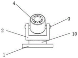
FIG. 1 is a perspective view of an LED lamp with a long service life according to the present invention;
FIG. 2 is a front view of an LED lamp with a long service life according to the present invention;
FIG. 3 is a schematic view of an internal structure of a housing of an LED lamp with a long service life according to the present invention;
fig. 4 is a side view of an LED lamp with a long service life according to the present invention.
Illustration of the drawings:
1. mounting a plate; 2. a support frame; 3. a damping rotating shaft; 4. a housing; 5. a support block; 6. a lamp body; 7. a lamp shade; 8. a heat sink; 9. a groove; 10. a bearing; 11. a through hole; 12. a fan blade; 13. moving the plate; 14. a rear cover; 15. a damping pad; 16. positioning a groove; 17. a motor.
Detailed Description
The technical solutions in the embodiments of the present invention will be clearly and completely described below with reference to the drawings in the embodiments of the present invention, and it is obvious that the described embodiments are only a part of the embodiments of the present invention, and not all of the embodiments. All other embodiments, which can be derived by a person skilled in the art from the embodiments given herein without making any creative effort, shall fall within the protection scope of the present invention.
In the description of the present invention, it should be noted that the terms "center", "upper", "lower", "left", "right", "vertical", "horizontal", "inner", "outer", etc., indicate orientations or positional relationships based on the orientations or positional relationships shown in the drawings, and are only for convenience of description and simplicity of description, but do not indicate or imply that the device or element being referred to must have a particular orientation, be constructed and operated in a particular orientation, and thus, should not be construed as limiting the present invention; the terms "first," "second," and "third" are used for descriptive purposes only and are not to be construed as indicating or implying relative importance, and furthermore, unless otherwise explicitly stated or limited, the terms "mounted," "connected," and "connected" are to be construed broadly and may be, for example, fixedly connected, detachably connected, or integrally connected; can be mechanically or electrically connected; they may be connected directly or indirectly through intervening media, or they may be interconnected between two elements. The specific meanings of the above terms in the present invention can be understood in specific cases to those skilled in the art.
Referring to fig. 1-4, one embodiment of the present invention is provided: an LED lamp with long service life comprises a shell 4 and a support frame 2, wherein the left and right ends of the inner diameter of the shell 4 are fixedly connected with support blocks 5, the inner sides of the support blocks 5 are respectively and fixedly connected with the left and right ends of a lamp body 6, the bottom end of the shell 4 is in threaded connection with a rear cover 14, the inner diameter of the bottom end of the shell 4 is in sliding connection with a movable plate 13, the middle part of the top end of the movable plate 13 is fixedly connected with a motor 17, the middle part of the bottom end of the support frame 2 is fixedly connected with the top end of an inner ring of a bearing 10, the top part of the inner side of the support frame 2 is rotatably connected with a damping rotating shaft 3, the inner sides of the damping rotating shaft 3 are fixedly connected with the bottoms of the left and right ends of the shell 4, the device is arranged on a target place through a through hole 11 on a mounting plate 1 by using a screw, the bearing 10 is arranged, the support frame 2 can be rotated to adjust the illumination direction of the lamp, the shell 4 can be rotated through the damping rotating shaft 3, and the horizontal angle of the support frame 2 can be adjusted, through the structure, the multi-angle adjustment of the lighting position of the lamp is realized, the installation position does not need to be replaced, and the lighting range can be enlarged.
The front end and the rear end of the lamp body 6 are fixedly connected with a plurality of radiating fins 8, the top end of the lamp body 6 is fixedly connected with a lampshade 7, the middle part of a rear cover 14 is fixedly connected with a damping pad 15, the damping pad 15 absorbs the vibration generated by the work of a motor 17, the service life of the motor 17 is prolonged, the inner wall of the shell 4 is provided with positioning grooves 16 corresponding to the left end and the right end of a movable plate 13, a fan blade 12 is fixedly connected on a shaft body of a driving end of the motor 17, the bottom end of an outer ring of a bearing 10 is fixedly connected at the middle part of the top end of a mounting plate 1, four corners of the top end of the mounting plate 1 are provided with through holes 11, the middle part of the top end of a support frame 2 is provided with a groove 9, the lamp body 6 is protected by the lampshade 7, the damage to electric elements inside the lamp body 6 is avoided, the motor 17 drives the fan blade 12 to rotate, the heat generated by the lamp body 6 is discharged through holes at the top end of the shell 4, the radiating fins 8 arranged on the lamp body 6, the radiating area of the lamp body 6 is increased, the heat dissipation efficiency of the lamp body 6 is improved, electrical components inside the lamp body 6 are protected, the service life of the device is prolonged, the lamp body 6 is supported by the supporting blocks 5, the rear cover 14 can be taken down from the shell 4 by rotating the rear cover 14, the movable plate 13 is downwards pulled, and the motor 17 on the movable plate 13 can be maintained or replaced.
The working principle is as follows: firstly, the device is arranged on a target ground through a through hole 11 on an installation plate 1 by using a screw, a support frame 2 can be rotated through an arranged bearing 10 to adjust the illumination direction of the lamp, a shell 4 can be rotated through an arranged damping rotating shaft 3 to adjust the horizontal angle between the shell 4 and the support frame 2, through the structure, the multi-angle adjustment of the illumination position of the lamp is realized, the illumination range can be expanded without changing the installation position, the lamp body 6 is protected by a lampshade 7 to avoid the damage of electrical components inside the lamp body 6, a motor 17 drives a fan blade 12 to rotate, the heat generated by the lamp body 6 is discharged through a hole at the top end of the shell 4, the heat radiation area of the lamp body 6 is increased through a heat radiation fin 8 arranged on the lamp body 6, the heat radiation efficiency of the lamp body 6 is improved, the electrical components inside the lamp body 6 are protected, and the service life of the device is prolonged, the lamp body 6 is supported by the supporting block 5, the rear cover 14 can be taken down from the shell 4 by rotating the rear cover 14, the movable plate 13 is pulled downwards, the motor 17 on the movable plate 13 can be maintained or replaced, the vibration generated by the work of the motor 17 is absorbed by the damping pad 15, and the service life of the motor 17 is prolonged.
Finally, it should be noted that: although the present invention has been described in detail with reference to the foregoing embodiments, it will be apparent to those skilled in the art that modifications may be made to the embodiments or portions thereof without departing from the spirit and scope of the utility model.
Claims (8)
1. The utility model provides a long service life's LED lamp, includes casing (4) and support frame (2), its characterized in that: equal fixedly connected with supporting shoe (5) in both ends about casing (4) internal diameter, both ends are controlled at lamp body (6) respectively to supporting shoe (5) inboard fixed connection, casing (4) bottom threaded connection has back lid (14), casing (4) bottom internal diameter department sliding connection has movable plate (13), movable plate (13) top middle part fixedly connected with motor (17), support frame (2) bottom middle part fixed connection is on the inner circle top of bearing (10), support frame (2) inboard top all rotates and is connected with damping pivot (3), both ends bottom is controlled at casing (4) to the equal fixed connection in damping pivot (3) inboard.
2. The LED lamp of claim 1, wherein: the front end and the rear end of the lamp body (6) are fixedly connected with a plurality of radiating fins (8).
3. The LED lamp of claim 1, wherein: the lamp body (6) top fixedly connected with lamp shade (7).
4. The LED lamp of claim 1, wherein: the middle part of the rear cover (14) is fixedly connected with a damping pad (15).
5. The LED lamp of claim 1, wherein: and positioning grooves (16) are formed in the inner wall of the shell (4) corresponding to the left end and the right end of the moving plate (13).
6. The LED lamp of claim 1, wherein: and the shaft body of the driving end of the motor (17) is fixedly connected with fan blades (12).
7. The LED lamp of claim 1, wherein: the bearing is characterized in that the bottom end of the outer ring of the bearing (10) is fixedly connected to the middle of the top end of the mounting plate (1), and through holes (11) are formed in four corners of the top end of the mounting plate (1).
8. The LED lamp of claim 1, wherein: the middle of the top end of the support frame (2) is provided with a groove (9).
Priority Applications (1)
| Application Number | Priority Date | Filing Date | Title |
|---|---|---|---|
| CN202122112326.1U CN215675104U (en) | 2021-09-03 | 2021-09-03 | LED lamp with long service life |
Applications Claiming Priority (1)
| Application Number | Priority Date | Filing Date | Title |
|---|---|---|---|
| CN202122112326.1U CN215675104U (en) | 2021-09-03 | 2021-09-03 | LED lamp with long service life |
Publications (1)
| Publication Number | Publication Date |
|---|---|
| CN215675104U true CN215675104U (en) | 2022-01-28 |
Family
ID=79959081
Family Applications (1)
| Application Number | Title | Priority Date | Filing Date |
|---|---|---|---|
| CN202122112326.1U Active CN215675104U (en) | 2021-09-03 | 2021-09-03 | LED lamp with long service life |
Country Status (1)
| Country | Link |
|---|---|
| CN (1) | CN215675104U (en) |
-
2021
- 2021-09-03 CN CN202122112326.1U patent/CN215675104U/en active Active
Similar Documents
| Publication | Publication Date | Title |
|---|---|---|
| CN111878731A (en) | High-efficient radiating LED lamp | |
| CN215675104U (en) | LED lamp with long service life | |
| CN218153836U (en) | LED lamp with ventilation and heat dissipation functions | |
| CN213362132U (en) | LED factory building lamp easily dispels heat | |
| CN210532329U (en) | LED heat dissipation lamp body structure | |
| CN210485415U (en) | High-power flexible LED wall washer lamp with adjustable light emitting angle | |
| CN209782256U (en) | Circulated heat dissipation formula LED lamp | |
| CN212776879U (en) | LED lamp with heat radiation structure | |
| CN213019405U (en) | Energy-saving environment-friendly LED lighting device | |
| CN206786368U (en) | A kind of rotating illuminating LED electricity-saving lamps | |
| CN218095854U (en) | LED lamp heat radiation structure | |
| CN111380003A (en) | LED heat dissipation support | |
| CN216383956U (en) | LED lamp with heat radiation structure | |
| CN111520691A (en) | Heat dissipation device of LED lamp | |
| CN210771855U (en) | Solar LED lamp capable of improving heat dissipation performance | |
| CN215061879U (en) | Wide board lamp of can adjusting luminance convenient to installation | |
| CN220911399U (en) | Novel LED display lamp | |
| CN210662464U (en) | LED light projecting lamp group | |
| CN219160156U (en) | LED lamp with automatic cooling device | |
| CN210462728U (en) | Plant illumination LED lamp with change light source structure | |
| CN214222870U (en) | LED lamp structure | |
| CN215259377U (en) | Heat dissipation device in LED lamp body | |
| CN213207507U (en) | LED lamp with good heat dissipation effect | |
| CN217643780U (en) | LED power of mixing of colors temperature can adjust luminance | |
| CN220436270U (en) | Mosquito-proof ball lamp bubble |
Legal Events
| Date | Code | Title | Description |
|---|---|---|---|
| GR01 | Patent grant | ||
| GR01 | Patent grant |