CN214595424U - Novel L-shaped curtain box - Google Patents
Novel L-shaped curtain box Download PDFInfo
- Publication number
- CN214595424U CN214595424U CN202022916465.5U CN202022916465U CN214595424U CN 214595424 U CN214595424 U CN 214595424U CN 202022916465 U CN202022916465 U CN 202022916465U CN 214595424 U CN214595424 U CN 214595424U
- Authority
- CN
- China
- Prior art keywords
- plate
- vertical plate
- transverse plate
- shaped
- transverse
- Prior art date
- Legal status (The legal status is an assumption and is not a legal conclusion. Google has not performed a legal analysis and makes no representation as to the accuracy of the status listed.)
- Active
Links
Images


Landscapes
- Curtains And Furnishings For Windows Or Doors (AREA)
Abstract
The utility model discloses a novel L-shaped curtain box, which comprises an internal corner connecting line and an L-shaped plate; the internal corner connecting line comprises a transverse plate, a first vertical plate and a second vertical plate, one end of the first vertical plate is fixedly connected with the lower end face of the transverse plate, one end of the second vertical plate is fixedly connected with the lower end face of the transverse plate, and the first vertical plate and the second vertical plate are arranged in parallel; a first clamping groove is formed among the first vertical plate, the transverse plate and the second vertical plate; the distance between the first vertical plate and the second vertical plate is less than the length of the transverse plate; the L-shaped plate comprises a vertical plate and a transverse plate which are connected into a whole, the upper end of the vertical plate is connected in a first clamping groove in a clamping mode, the lower end of the vertical plate is fixedly connected with one end of the transverse plate, and the length of the vertical plate is larger than that of the transverse plate. The utility model discloses a novel L shape curtain box simple structure, the equipment is convenient, has reduced material cost and cost of labor, has improved the installation effectiveness.
Description
Technical Field
The utility model belongs to the technical field of interior decoration technique and specifically relates to a novel L shape curtain box.
Background
The curtain box is an important part in indoor decoration and is an important facility for hiding curtain heads of the curtain. Curtain holders generally have two forms: one is that the room has a suspended ceiling, the curtain box should be hidden in the suspended ceiling, and the curtain box and the suspended ceiling are completed together when the suspended ceiling is made on the top; the other type is that the room is not provided with a suspended ceiling, and the curtain box is fixed on the wall and is integrated with the window frame sleeve. The traditional decoration method is generally a structure that a notch is reserved on a ceiling to accommodate a curtain, a plywood base layer is usually adopted at the periphery of the notch, a gypsum board is pasted outside, the latex paint is brushed on the surface, the construction and installation space is limited, the materials are not only complicated but also wasted, and the energy conservation and the environmental protection are insufficient. On the other hand, the width and the height of the notch are mostly about 150mm multiplied by 200mm, the notch is directly exposed, and the structures such as a roller shutter bracket, hardware fittings and the like can be clearly seen, so that the integral decorative effect of the ceiling is influenced. In addition, the plywood base layer has poor fire resistance and is easy to deform and crack when meeting damp, and some synthetic wood boards can release harmful gases such as formaldehyde, TOVC and the like, so that the indoor environment quality is not facilitated.
Traditional curtain box's mounting means is more complicated, and the way of curtain box among the present assembled type glazed brilliant furred ceiling system is milling the V groove in the mill, bend at the scene with the organic board and take shape, the workman need install a row of angle sign indicating number to the elbow, and consolidate with wood-plastic panel in the curtain box intracavity, prevent that the curtain box warp, still need install the shrouding at last and cover the inner chamber, through several processes with the inside reinforcement equipment of curtain box, just can install the curtain box at last, the curtain box consumes more angle sign indicating number, the screw, organic plate, the workman also need pay attention to control the roughness of curtain box and top panel department of meeting strictly when the installation, so the field erection is loaded down with trivial details, consume more man-hour, lead to the cost of labor higher, in the built-in field market of well low-end, do not possess the competitive advantage in the price.
Chinese patent CN201811419225.5 discloses a curtain box structure, a curtain box system and an assembling method thereof, wherein the curtain box structure comprises a curtain box main body and a curtain box partition; the curtain box main body comprises a curtain box top plate and an L-shaped side plate; the curtain box partition comprises a first side plate and a second side plate; the first side plate is connected with the second side plate through a connecting bottom plate; the top end of the second side plate is connected with the top plate of the curtain box; the L-shaped side plate comprises a side plate vertical plate and a side plate flat plate, the top end of the side plate vertical plate is connected with the curtain box top plate, and the side plate flat plate is connected to the bottom end of the side plate vertical plate; in the vertical direction, the side plate flat plate is positioned above the connecting bottom plate. According to the curtain box structure, the curtain box system and the assembling method thereof, the curtain box main body and the curtain box partition are designed in a modularized mode and then assembled, so that the rapid assembly can be realized, the installation efficiency is greatly improved, the modularized production can be realized, and the production cost is reduced. However, the curtain box main body and the curtain box partition in the patent are still respectively formed by connecting a plurality of small parts through connecting pieces, the structure is complex, the assembly is not simple and convenient enough, and the price still has no competitive advantage.
SUMMERY OF THE UTILITY MODEL
In order to overcome the defects of the prior art, the utility model aims to provide a novel L-shaped curtain box.
In order to solve the above problem, the utility model adopts the following technical scheme:
a novel L-shaped curtain box comprises an internal corner connecting line and an L-shaped plate;
the internal corner connecting line comprises a transverse plate, a first vertical plate and a second vertical plate, one end of the first vertical plate is fixedly connected with the lower end face of the transverse plate, one end of the second vertical plate is fixedly connected with the lower end face of the transverse plate, and the first vertical plate and the second vertical plate are arranged in parallel; a first clamping groove is formed among the first vertical plate, the transverse plate and the second vertical plate; the distance between the first vertical plate and the second vertical plate is smaller than the length of the transverse plate;
the L-shaped plate comprises a vertical plate and a transverse plate which are connected into a whole, the upper end of the vertical plate is clamped in the first clamping groove, the lower end of the vertical plate is fixedly connected with one end of the transverse plate, and the length of the vertical plate is greater than that of the transverse plate.
Preferably, a first screw positioning groove is formed in the side face of the upper portion of the second vertical plate, and the second vertical plate is connected with the vertical plate into a whole through screws driven into the first screw positioning groove.
Preferably, the corner connector further comprises a corner connector, a second screw positioning groove is formed in the side face of the lower portion of the vertical plate, and the vertical plate is connected with a side wall body through the corner connector and screws driven into the second screw positioning groove.
Preferably, a third screw positioning groove is formed in the lower end face of the transverse plate, and the transverse plate is connected with the top ceiling through screws screwed into the third screw positioning groove.
Preferably, the second vertical plate and the transverse plate are connected through an inclined reinforcing plate.
Preferably, one end of the upper end surface of the transverse plate is provided with a notch groove.
Preferably, the length of the first riser is less than the length of the second riser.
Preferably, the L-shaped plate is a hollow structure.
Preferably, the decorative molding also comprises an F-shaped decorative molding, the F-shaped decorative molding comprises a first transverse plate, a second transverse plate and a third vertical plate, one end of the first transverse plate is connected to the third vertical plate, one end of the second transverse plate is connected to the third vertical plate, the first transverse plate and the second transverse plate are positioned on the same side of the third vertical plate, and the first transverse plate and the second transverse plate are arranged in parallel; the first transverse plate, the second transverse plate and the third vertical plate form a second clamping groove, and the other end of the transverse plate is clamped in the second clamping groove.
The utility model also provides a novel L-shaped curtain box installation method, which comprises the following steps:
the internal corner connecting line and the L-shaped plate are connected into a whole through the first clamping groove;
fixing the upper end surface of the transverse plate of the internal corner connecting line to a top ceiling through a screw;
and fixing the vertical plate of the L-shaped plate on a side wall.
Compared with the prior art, the utility model discloses a technical effect embodies:
the utility model discloses a novel L shape curtain box is whole to be connected lines and L shaped plate by the reentrant corner and constitutes, simple structure, and the equipment is convenient, compares in the curtain box structure of the tradition technology of bending, the utility model discloses a consumption of angle sign indicating number, screw when novel L shape curtain box significantly reduces the assembly has reduced material cost and cost of labor, has improved the installation effectiveness, has promoted the competitive advantage of assembled glazed brilliant furred ceiling in the built-in field of middle and low end. In addition, the internal corner connecting lines avoid the problem that a gap exists between the curtain box adopting the bending process and the ceiling at the top, improve the appearance effect of the internal corner gap, and make the whole body more attractive.
The utility model discloses a novel installation method of L shape curtain box easy operation installs easily reliably, and the installation effectiveness is high.
Additional advantages, objects, and features of the invention will be set forth in part in the description which follows and in part will become apparent to those having ordinary skill in the art upon examination of the following or may be learned from practice of the invention. The objectives and other advantages of the invention will be realized and attained by the structure particularly pointed out in the written description and claims hereof as well as the appended drawings.
It will be appreciated by those skilled in the art that the objects and advantages that can be achieved with the present invention are not limited to the details set forth above, and that these and other objects that can be achieved with the present invention will be more clearly understood from the following detailed description.
Drawings
The accompanying drawings, which are included to provide a further understanding of the invention and are incorporated in and constitute a part of this application, illustrate embodiment(s) of the invention and together with the description serve to explain the principles of the invention. Many aspects of the invention will be better understood with reference to the following drawings. The components in the drawings are not necessarily to scale, emphasis instead being placed upon clearly illustrating the principles of the present invention. In the drawings:
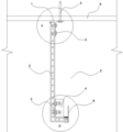
fig. 1 is a schematic structural view of a novel L-shaped curtain rail provided in embodiment 1 of the present invention;
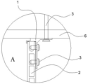
FIG. 2 is an enlarged view of a portion of FIG. 1 at A;
FIG. 3 is an enlarged view of a portion of FIG. 1 at B;
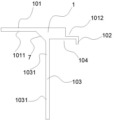
fig. 4 is a schematic structural diagram of a cross section of an internal corner connecting line provided in embodiment 1 of the present invention;
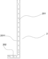
fig. 5 is a schematic structural view of an L-shaped plate provided in embodiment 1 of the present invention;
fig. 6 is a schematic structural view of an F-shaped molding provided in embodiment 1 of the present invention.
In the figure, 1, a female corner connecting line, 2, an L-shaped plate, 3, a screw, 4, an angle code, 5, a wall body, 6, a ceiling, 7, a reinforcing plate, 8, an F-shaped decorative line, 101, a transverse plate, 102, a first vertical plate, 103, a second vertical plate, 104, a first clamping groove, 201, a vertical plate, 202, a transverse plate, 801, a first transverse plate, 802, a second transverse plate, 803, a third vertical plate, 804, a second clamping groove, 1011, a third screw positioning groove, 1012, a notch groove, 1031, a first screw positioning groove, 2011 and a second screw positioning groove.
Detailed Description
In order to make the objects, technical solutions and advantages of the present invention more clearly understood, the present invention is further described in detail below with reference to the accompanying drawings and embodiments. It should be understood that the specific embodiments described herein are for purposes of illustration only and are not intended to limit the invention.
Furthermore, it should be noted that the present invention is not obscured by unnecessary details, and only the structures and/or processing steps closely related to the solution according to the present invention are shown in the drawings, while other details not relevant to the present invention are omitted.
In addition, it should be noted that, in the embodiments of the present invention, the term "connected" may be a straight connection or an indirect connection with an additional connecting member in the middle, unless otherwise specified.
Hereinafter, embodiments of the present invention will be described with reference to the accompanying drawings. In the drawings, the same reference numerals denote the same or similar parts, or the same or similar steps.
Example 1
The embodiment 1 of the utility model provides a novel L-shaped curtain box, the structure of which is shown in figures 1-6. A novel L-shaped curtain box comprises an internal corner connecting line 1 and an L-shaped plate 2; the internal corner connecting line 1 comprises a transverse plate 101, a first vertical plate 102 and a second vertical plate 103, one end of the first vertical plate 102 is fixedly connected with the lower end face of the transverse plate 101, one end of the second vertical plate 103 is fixedly connected with the lower end face of the transverse plate 101, and the first vertical plate 102 and the second vertical plate 103 are arranged in parallel; a first clamping groove 104 is formed among the first vertical plate 102, the transverse plate 101 and the second vertical plate 103; the distance between the first vertical plate 102 and the second vertical plate 103 is smaller than the length of the transverse plate 101, that is, the first vertical plate 102 and the second vertical plate 103 cannot be located at two ends of the lower end surface of the transverse plate 101 at the same time, so that a plate surface with a certain length can be reserved on the lower end surface of the transverse plate 101 for being connected with the top ceiling 6;
l shaped plate 2 is including linking into an organic whole vertical board 201 and horizontal board 202, and the upper end joint of vertical board 201 is in first joint recess 104, the lower extreme of vertical board 201 and the one end fixed connection of horizontal board 202, and the length of vertical board 201 is greater than the length of horizontal board 202.
The utility model discloses a novel L shape curtain box is when using, connects into an integrated entity earlier reentrant corner connecting lines 1 and L shaped plate through reentrant corner connecting lines 1 on first joint recess 104, then with reentrant corner connecting lines 1 through its diaphragm 101 under the terminal surface reserve for the face screw 3 fixed connection to top surface ceiling 6 on, just so accomplished novel L shape curtain box's installation. After the installation, the vertical plate 201 of the L-shaped plate can hide the curtain head at the inner side of the vertical plate 201, so as to play a role of beautiful decoration.
The utility model discloses a novel L shape curtain box is whole to be connected lines 1 and L shaped plate 2 by the reentrant corner and constitutes, simple structure, and the equipment is convenient, compares in the curtain box structure of traditional technology of bending, the utility model discloses a consumption of angle sign indicating number, screw when novel L shape curtain box significantly reduces the assembly has reduced material cost and cost of labor, has improved the installation effectiveness, has promoted the competitive advantage of assembled luck brilliant furred ceiling in the built-in field of middle and low end. In addition, the internal corner connecting lines 1 avoid the problem that a gap exists between the curtain box adopting the bending process and the top ceiling 6, improve the appearance effect of the internal corner gap, and are more attractive integrally.
Preferably, a first screw positioning groove 1031 is formed on the upper side surface of the second vertical plate 103, and the second vertical plate 103 is integrally connected with the vertical plate 201 through a screw 3 screwed into the first screw positioning groove 1031. Under the condition that reentrant corner moulding 1 and L shaped plate 2 pass through first joint recess 104 and connect, through addding first screw location recess 1031 in the upper portion side of second riser 103, can consolidate the joint strength between reentrant corner moulding 1 and the L shaped plate 2 through driving in screw 3, make the connection between them more firm. The first screw positioning recesses 1031 may be provided in at least two rows in the height direction of the second riser 103, as shown in fig. 1, 2, and 4. In addition, the first screw positioning recess 1031 is arranged to fix all the screws 3 nailed on the second vertical plate 103 at specific positions, that is, the positions of the first screw positioning recesses 1031, so that the nailed screws 3 are arranged orderly and visually, disorder feeling caused by the nailing positions at will can be avoided, and the attractiveness of the curtain box is improved.
Preferably, the utility model discloses a novel L shape curtain box still includes angle sign indicating number 4, has seted up second screw positioning groove 2011 on the lower part side of vertical board 201, and vertical board 201 is connected with side wall body through the screw 3 of nailing in angle sign indicating number 4 and second screw positioning groove 2011. Because the whole curtain box is hung below the top ceiling 6, the vertical plate 201 can be fixed on the side wall 5 connected with the top ceiling 6 through the screws 3 by the corner connectors 4, so that the connection firmness of the curtain box with the top ceiling 6 and the side wall 5 is enhanced, the curtain box is prevented from falling due to the loosening of the screws 3 in long-time use, and the use safety of the curtain box is improved.
Preferably, a third screw positioning groove 1011 is formed on the lower end surface of the horizontal plate 101, and the horizontal plate 101 is connected to the top ceiling 6 through a screw 3 screwed into the third screw positioning groove 1011. When the curtain box is used, the internal corner connecting line 1 is fixedly connected with the top ceiling 6 through the screw 3 which is screwed into the lower end face of the transverse plate 101, and the upper end face of the transverse plate 101 is attached to the top ceiling 6, so that the problem that a gap exists between the curtain box adopting a bending process and the top face can be avoided, and the appearance effect of the internal corner gap is improved; on the other hand, the third screw positioning groove 1011 is arranged so that all the screws 3 nailed on the lower end surface of the transverse plate 101 are located at specific positions, namely the positions of the third screw positioning grooves 1011, so that the nailed screws 3 are arranged orderly and integrally, the visual appearance is more attractive, the disordered feeling caused by the random nailing positions can be avoided, and the attractiveness of the curtain box is improved.
Preferably, the second vertical plate 103 is connected with the transverse plate 101 through an inclined reinforcing plate 7, and compared with a right-angle connection mode between the second vertical plate 103 and the transverse plate 101, the connection mode with a certain inclined angle can enable the internal corner connecting line 1 to have higher structural strength and better bearing and deformation resistance; on the other hand, the inclination angle between the second vertical plate 103 and the horizontal plate 101 is designed to facilitate the nailing operation in the first screw positioning recess 1031 and the third screw positioning recess 1011. In addition, the second vertical plate 103 and the horizontal plate 101 can also be connected in an arc angle connection mode.
Preferably, a notch 1012 is formed at one end of the upper end surface of the horizontal plate 101. The notch groove 1012 can reduce the structural weight of the internal corner connecting line 1, so that the structure is lighter, the installation of a curtain box is convenient, and the material consumption cost is reduced; on the other hand, the notch groove 1012 can make the internal corner connecting line 1 more modeling, giving people different visual experiences.
Preferably, the length of the first riser 102 is less than the length of the second riser 103. The first riser 102 only needs to protrude the lower terminal surface of the transverse plate 101, can with the second riser 103, the first joint recess 104 that forms joint L shaped plate 2 between the transverse plate 101 can, be equipped with on the lateral surface of the vertical board 201 of L shaped plate 2 and decorate the tectorial membrane, can play the effect of pleasing to the eye curtain head of curtain, if the length overlength of first riser 102, can cover the decoration tectorial membrane face of partial vertical board 201, influence the holistic aesthetic property of curtain box.
Preferably, the L-shaped plate 2 is a hollow structure, such as a honeycomb structure, so that the overall weight of the L-shaped plate 2 can be reduced, and the L-shaped plate is lighter and more convenient to mount; on the other hand, the cost of material consumption can be reduced, so that the curtain box has price competitive advantage.
Preferably, the novel L-shaped curtain rail of the present invention further includes an F-shaped molding 8, as shown in fig. 1, 3, and 6. The F-shaped decorative molding 8 comprises a first transverse plate 801, a second transverse plate 802 and a third vertical plate 803, wherein one end of the first transverse plate 801 is connected to the third vertical plate 803, one end of the second transverse plate 802 is connected to the third vertical plate 803, the first transverse plate 801 and the second transverse plate 802 are positioned on the same side of the third vertical plate 803, and the first transverse plate 801 and the second transverse plate 802 are arranged in parallel; a second clamping groove 804 is formed among the first transverse plate 801, the second transverse plate 802 and the third vertical plate 803, and the other end of the transverse plate 202 is clamped in the second clamping groove 804. The F-shaped decorative lines 8 can cover the lower end face of the L-shaped plate 2, so that the overall appearance effect of the curtain box is better, and the visual aesthetic feeling is improved. In order to strengthen the firmness of the connection between the F-shaped moulding 8 and the L-shaped plate 2, the F-shaped moulding 8 can be reinforced and connected by nail-free glue.
The utility model discloses an reentrant corner connecting lines 1, L shaped plate 2 and F shape moulding 8 all can be made at the mill die sinking, compare in the curtain box structure of the technology of bending, the utility model discloses a novel L shape curtain box has simplified curtain box's whole molding, has guaranteed the technology homogeneity of curtain box when batch production, has avoided the good of the technology of bending to be uneven, and the installation is also more simple and convenient, has reduced the curtain box cost on the whole.
Example 2
The embodiment 2 of the utility model provides a novel mounting method of L shape curtain box, including the following steps:
(1) the internal corner connecting line 1 and the L-shaped plate 2 are connected into a whole through a first clamping groove 104;
(2) fixing the upper end surface of the transverse plate 101 of the internal corner connecting line 1 on the top ceiling 6 through a screw 3;
(3) the vertical plates 201 of the L-shaped plate 2 are fixed on the side wall 5, specifically, the angle connectors 4 can be installed on two sides of the L-shaped plate 2, and the L-shaped plate 2 is fixed on the side wall 5 by the cooperation of the angle connectors 4 and the screws 3.
Under the condition that the novel L-shaped curtain box comprises the F-shaped decorative molding 8, further comprising the following steps:
(4) the L-shaped plate 2 and the F-shaped decorative moulding 8 are clamped into a whole through the second clamping groove 804 and are reinforced by nail-free glue.
The utility model discloses a novel installation method of L shape curtain box only need on the spot with reentrant corner connecting lines 1, L shaped plate 2 and F shape moulding 8 carry out simple equipment can, installation method easy operation, the installation is light reliable, the installation effectiveness is high.
The present invention is not limited to the above-described specific embodiments, and various modifications and changes are possible. Any modification, equivalent replacement, improvement and the like of the above embodiments according to the technical spirit of the present invention should be included in the scope of the present invention.
Claims (9)
1. A novel L-shaped curtain box is characterized by comprising an internal corner connecting line and an L-shaped plate;
the internal corner connecting line comprises a transverse plate, a first vertical plate and a second vertical plate, one end of the first vertical plate is fixedly connected with the lower end face of the transverse plate, one end of the second vertical plate is fixedly connected with the lower end face of the transverse plate, and the first vertical plate and the second vertical plate are arranged in parallel; a first clamping groove is formed among the first vertical plate, the transverse plate and the second vertical plate; the distance between the first vertical plate and the second vertical plate is smaller than the length of the transverse plate;
the L-shaped plate comprises a vertical plate and a transverse plate which are connected into a whole, the upper end of the vertical plate is clamped in the first clamping groove, the lower end of the vertical plate is fixedly connected with one end of the transverse plate, and the length of the vertical plate is greater than that of the transverse plate.
2. The novel L-shaped curtain box as claimed in claim 1, wherein the second vertical plate is provided with a first screw positioning groove on the upper side surface, and the second vertical plate is connected with the vertical plate into a whole through a screw driven into the first screw positioning groove.
3. The novel L-shaped curtain rail as claimed in claim 2, further comprising an angle bracket, wherein a second screw positioning groove is formed in the lower side surface of the vertical plate, and the vertical plate is connected with the side wall through the angle bracket and a screw screwed into the second screw positioning groove.
4. The novel L-shaped curtain box as claimed in claim 3, wherein a third screw positioning groove is formed in the lower end face of the transverse plate, and the transverse plate is connected with the top ceiling through a screw screwed into the third screw positioning groove.
5. The novel L-shaped curtain rail as claimed in any one of claims 1 to 4, wherein the second vertical plate and the transverse plate are connected by an inclined reinforcing plate.
6. The novel L-shaped curtain rail as claimed in claim 5, wherein a notch groove is formed at one end of the upper end surface of the transverse plate.
7. The novel L-shaped headrail of claim 6, wherein the first riser has a length less than the length of the second riser.
8. The novel L-shaped curtain rail as claimed in claim 7, wherein the L-shaped plate is a hollow structure.
9. The novel L-shaped curtain box as claimed in claim 8, further comprising an F-shaped molding, wherein the F-shaped molding comprises a first transverse plate, a second transverse plate and a third vertical plate, one end of the first transverse plate is connected to the third vertical plate, one end of the second transverse plate is connected to the third vertical plate, the first transverse plate and the second transverse plate are located on the same side of the third vertical plate, and the first transverse plate and the second transverse plate are arranged in parallel; the first transverse plate, the second transverse plate and the third vertical plate form a second clamping groove, and the other end of the transverse plate is clamped in the second clamping groove.
Priority Applications (1)
| Application Number | Priority Date | Filing Date | Title |
|---|---|---|---|
| CN202022916465.5U CN214595424U (en) | 2020-12-08 | 2020-12-08 | Novel L-shaped curtain box |
Applications Claiming Priority (1)
| Application Number | Priority Date | Filing Date | Title |
|---|---|---|---|
| CN202022916465.5U CN214595424U (en) | 2020-12-08 | 2020-12-08 | Novel L-shaped curtain box |
Publications (1)
| Publication Number | Publication Date |
|---|---|
| CN214595424U true CN214595424U (en) | 2021-11-05 |
Family
ID=78429366
Family Applications (1)
| Application Number | Title | Priority Date | Filing Date |
|---|---|---|---|
| CN202022916465.5U Active CN214595424U (en) | 2020-12-08 | 2020-12-08 | Novel L-shaped curtain box |
Country Status (1)
| Country | Link |
|---|---|
| CN (1) | CN214595424U (en) |
-
2020
- 2020-12-08 CN CN202022916465.5U patent/CN214595424U/en active Active
Similar Documents
| Publication | Publication Date | Title |
|---|---|---|
| CN205712903U (en) | A kind of indoor facing wall mounting decoration panel and decoration panel hanging device | |
| CN210177866U (en) | Wall keel | |
| CN214614935U (en) | Can install fast and fall level furred ceiling connecting piece and furred ceiling system | |
| CN214595424U (en) | Novel L-shaped curtain box | |
| CN209277487U (en) | A kind of cellular system of overlength overhanging vertical decorative strip | |
| CN209958579U (en) | Assembled curtain mounting structure | |
| CN112450706A (en) | Novel L-shaped curtain box and installation method | |
| CN115075454A (en) | Integrated closing-in piece for suspended ceiling | |
| CN210177868U (en) | Open-word type wall fossil fragments | |
| CN112554425A (en) | Fall-level ceiling connecting piece capable of being installed rapidly, ceiling system and installation method | |
| CN112443068A (en) | Ceiling access hole structure and mounting method | |
| CN210563149U (en) | Wall keel shaped like Chinese character' wang | |
| CN210177867U (en) | Soil style of calligraphy wall fossil fragments | |
| CN204804139U (en) | Brand -new compound furred ceiling | |
| CN216075843U (en) | Eye-splice drop-level ceiling module and ceiling assembly | |
| CN212336485U (en) | Cellular board staggered-layer lap-joint section bar | |
| CN215442556U (en) | Frame type curtain wall connecting system with transverse large lines | |
| CN219699537U (en) | Fish scale screen | |
| CN220014155U (en) | Aluminum-plastic plate system for large ribbon of unit curtain wall | |
| CN204804136U (en) | Mounting structure of inclined plane buckle and compound furred ceiling medium dip face | |
| CN214498193U (en) | Indoor decoration wallboard system of assembled installation | |
| CN218405969U (en) | Changeable vertical stile | |
| CN212405819U (en) | Connection structure for assembled building wall decoration panel | |
| CN215292089U (en) | Glass mounting structure | |
| CN201326257Y (en) | Plastic-aluminum decorative buckle plate |
Legal Events
| Date | Code | Title | Description |
|---|---|---|---|
| GR01 | Patent grant | ||
| GR01 | Patent grant |