CN212306604U - But gardens are with height-adjusting's laxative machine - Google Patents
But gardens are with height-adjusting's laxative machine Download PDFInfo
- Publication number
- CN212306604U CN212306604U CN202020715968.3U CN202020715968U CN212306604U CN 212306604 U CN212306604 U CN 212306604U CN 202020715968 U CN202020715968 U CN 202020715968U CN 212306604 U CN212306604 U CN 212306604U
- Authority
- CN
- China
- Prior art keywords
- bottom plate
- backup pad
- vertical
- lift
- lift backup
- Prior art date
- Legal status (The legal status is an assumption and is not a legal conclusion. Google has not performed a legal analysis and makes no representation as to the accuracy of the status listed.)
- Active
Links
Images

Abstract
The utility model discloses a gardens are with laxative machine of adjustable height, comprising a base plate, the top of bottom plate is provided with the lift backup pad, the top of lift backup pad is provided with spouts the medicine subassembly, the bottom plate with be provided with the elevating system who adjusts lift backup pad height between the lift backup pad, elevating system includes and rotates the vertical threaded rod of being connected, sets firmly in the elevator of lift backup pad lateral wall, drive vertical threaded rod pivoted drive assembly and set up the flexible supporting component between bottom plate and lift backup pad with the bottom plate, the lift screw hole has been seted up to the elevator, vertical threaded rod wear to locate lift screw hole and with elevator threaded connection, flexible supporting component's lower extreme and bottom plate fixed connection, flexible supporting component's upper end and lift backup pad fixed connection. It is labour saving and time saving not only, and can carry out nimble regulation to the height of laxative.
Description
Technical Field
The utility model relates to a gardens technical field, in particular to but gardens are with height-adjusting's laxative machine.
Background
Gardens need to carry out laxative to vegetation in the gardens in the maintenance process, and laxative has a range of benefits for vegetation in the gardens.
Firstly, the prevention and treatment cost by using pesticides is lower; and secondly, the prevention and control effect is quick, the efficiency is high, the spreading of plant diseases and insect pests can be quickly and effectively controlled, the instant effect is achieved, the application range of prevention and control objects is wide, most of the pests, and a plurality of diseases and weeds can be prevented and controlled by chemical pesticides, which are difficult to achieve by other prevention and control methods.
At present, the pesticide spraying method commonly used by workers still adopts a manual sprayer to spray pesticide, the pesticide spraying rod needs to be held by hands to move back and forth to spray pesticide in the traditional method, the method is not only very labor-consuming, but also has uneven height due to different plant types, when the plants with higher growth are sprayed, the hands need to be inclined upwards all the time, and the trouble is brought to the workers.
SUMMERY OF THE UTILITY MODEL
Not enough to prior art exists, the utility model aims to provide a but gardens are with height-adjusting's laxative machine, its labour saving and time saving not only, and can adjust in a flexible way the height of laxative.
The above technical purpose of the present invention can be achieved by the following technical solutions:
the utility model provides a height-adjustable laxative machine is used in gardens, includes the bottom plate, the top of bottom plate is provided with the lift backup pad, the top of lift backup pad is provided with spouts the medicine subassembly, the bottom plate with be provided with the elevating system who adjusts lift backup pad height between the lift backup pad, elevating system includes the vertical threaded rod of being connected with the bottom plate rotation, set firmly in the elevator of lift backup pad lateral wall, drive vertical threaded rod pivoted drive assembly and set up the flexible supporting component between bottom plate and lift backup pad, the elevator has seted up the lift screw hole, vertical threaded rod wear to locate the lift screw hole and with elevator threaded connection, the lower extreme and the bottom plate fixed connection of flexible supporting component, the upper end and the lift backup pad fixed connection of flexible supporting component.
Through adopting above-mentioned technical scheme, drive assembly, drive assembly drives vertical threaded rod and rotates, and vertical threaded rod drives the elevator and reciprocates, and the elevator drives the lift backup pad and reciprocates, and the lift backup pad drives spouts the medicine subassembly and reciprocates to, realize the control to spouting the medicine subassembly and go up and down, and then, realize carrying out the operation of laxative to the uneven plant of different kinds, it is labour saving and time saving not only, and can carry out nimble regulation to the height of laxative.
The utility model discloses further set up to: the driving assembly comprises a driving motor fixedly arranged on the bottom plate, a driving gear arranged on an output shaft of the driving motor and a driven gear arranged on the vertical threaded rod, and the driving gear is meshed with the driven gear.
Through adopting above-mentioned technical scheme, start driving motor, driving motor drives the driving gear and rotates, and the driving gear drives driven gear and rotates, and driven gear drives vertical threaded rod and rotates, and vertical threaded rod drives the lift backup pad and reciprocates to the realization makes things convenient for staff's laxative operation to the regulation of laxative subassembly height.
The utility model discloses further set up to: the telescopic supporting component comprises a vertical outer pipe, a vertical inner rod and a positioning bolt, the lower end of the vertical outer pipe is fixedly connected to the bottom plate, the upper end of the vertical inner rod is fixedly connected to the lifting supporting plate, the vertical outer pipe and the vertical inner rod are sleeved, the vertical outer pipe is provided with a positioning threaded hole, the positioning bolt is in threaded connection with the positioning threaded hole, and the end portion of the positioning bolt abuts against the outer peripheral face of the vertical inner rod.
Through adopting above-mentioned technical scheme, the mode that flexible supporting component adopted vertical outer tube and vertical interior pole to cup joint mutually makes flexible component's length become very nimble, and vertical interior pole can follow the motion of vertical threaded rod and slide from top to bottom, treats the rigidity of lift backup pad, adopts the mode of set nut butt to vertical interior pole, realizes the fixed to vertical interior pole to the realization is to the fixed of lift backup pad height.
The utility model discloses further set up to: the telescopic supporting components are four groups, and the four groups of telescopic components are positioned at four end corners of the lifting supporting plate.
Through adopting above-mentioned technical scheme, flexible subassembly sets up to four groups, strengthens the supporting role of bottom plate and lift backup pad and strengthens the stability between bottom plate and the lift backup pad.
The utility model discloses further set up to: spout the medicine subassembly including set up in the medical kit of lift backup pad upper surface, set up in the water pump of medical kit, communicate in the water pump import and arrange the inside inhaling pencil of medical kit in, communicate in the water pump export and arrange the play pencil of water pump top in and set up in the sprinkler head of a pencil top.
By adopting the technical scheme, the water pump is started, and the medicine in the water tank is sprayed on the plants through the medicine suction pipe, the water pump, the medicine outlet pipe and the spraying head in sequence, so that the medicine spraying operation on the plants is completed; simple structure and convenient operation.
The utility model discloses further set up to: the sprinkler head is provided in plurality.
By adopting the technical scheme, the contact area of the medicine and the vegetation is increased, and the working efficiency is improved.
The utility model discloses further set up to: the upper end of medical kit is provided with the top cap, the top cap sets firmly in the first apron of medical kit upper end and articulated the second apron that sets up in first apron including setting firmly, the one end that first apron was kept away from to the second apron is fixed in the medical kit lateral wall through hasp locking.
Through adopting above-mentioned technical scheme, the medicine is poured into to the medical kit to the staff to the setting of second apron, and the setting of hasp prevents that the second apron from opening, the entering of pollutant.
The utility model discloses further set up to: and a U-shaped pushing frame is fixedly arranged on the side wall of the bottom plate.
Through adopting above-mentioned technical scheme, the setting of U type propelling movement frame makes things convenient for the staff to promote whole laxative machine device.
The utility model discloses further set up to: and the lower surface of the bottom plate is respectively provided with a brake universal wheel at the positions of four end angles.
Through adopting above-mentioned technical scheme, the setting of brake universal wheel makes things convenient for the removal of whole laxative machine device.
To sum up, the utility model discloses following beneficial effect has: drive assembly, drive assembly drives vertical threaded rod and rotates, and vertical threaded rod drives the elevator and reciprocates, and the elevator drives the lift backup pad and reciprocates, and the lift backup pad drives spouts the medicine subassembly and reciprocates to, realize the control to spouting the medicine subassembly and go up and down, and then, realize carrying out the operation of laxative to the uneven plant of different kinds, its labour saving and time saving not only, and can carry out nimble regulation to the height of laxative.
Drawings
FIG. 1 is a schematic view of the overall structure of the present invention;
fig. 2 is a schematic sectional structure of the present invention.
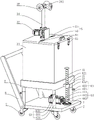
In the figure, 1, a bottom plate; 2. lifting the supporting plate; 21. a limiting frame; 3. a pesticide spraying component; 31. a medicine chest; 32. a water pump; 33. a drug suction tube; 34. a medicine outlet pipe; 341. a connector; 35. a sprinkler head; 41. a vertical threaded rod; 42. a lifting block; 421. a lifting threaded hole; 43. a telescopic support assembly; 431. a vertical outer tube; 432. a vertical inner rod; 433. positioning the bolt; 44. a drive assembly; 441. a drive motor; 442. a driving gear; 443. a driven gear; 5. a top cover; 51. a first cover plate; 52. a second cover plate; 521. a handle; 53. locking; 54. a hinge; 6. a U-shaped pushing frame; 7. and (5) braking the universal wheel.
Detailed Description
The present invention will be described in further detail with reference to the accompanying drawings.
Referring to fig. 1, the height-adjustable pesticide sprayer for gardens disclosed by the utility model comprises a bottom plate 1, wherein the bottom plate 1 is rectangular, and the lower surface of the bottom plate 1 is respectively provided with brake universal wheels 7 at four end angles thereof, so that the movement of the whole pesticide sprayer device is facilitated; a lifting support plate 2 is arranged above the bottom plate 1, and a lifting mechanism for adjusting the height of the lifting support plate 2 is arranged between the bottom plate 1 and the lifting support plate 2; the lifting mechanism comprises a vertical threaded rod 41, a lifting block 42, four groups of telescopic supporting components 43 and a driving component 44, the four groups of telescopic supporting components 43 are respectively positioned at four end angles of the lifting supporting plate 2, the vertical threaded rod 41 is positioned between the two adjacent groups of telescopic supporting components 43, each group of telescopic supporting components 43 comprises a vertical outer pipe 431, a vertical inner rod 432 and a positioning bolt 433, the lower end of the vertical outer pipe 431 is welded on the upper surface of the bottom plate 1, the lower end of the vertical inner rod 432 is sleeved on the upper end of the vertical outer pipe 431, and the upper end of the vertical inner rod 432 is welded on the lower bottom surface of the; the vertical outer pipe 431 is provided with a positioning threaded hole, the positioning bolt 433 is in threaded connection with the positioning threaded hole, and the end of the positioning bolt 433 abuts against the outer peripheral surface of the vertical inner rod 432.
The lifting block 42 is welded on the side surface of the lifting support plate 2, the lifting block 42 is provided with a lifting threaded hole 421, and the vertical threaded rod 41 penetrates through the lifting threaded hole 421 and is in threaded connection with the lifting block 42; the bottom end of the vertical threaded rod 41 is rotatably connected to the upper surface of the bottom plate 1.
The driving assembly 44 includes a driving motor 441, a driving gear 442 and a driven gear 443, the driving motor 441 is mounted on the upper surface of the bottom plate 1, the driving gear 442 is welded to the output shaft of the driving motor 441, the driven gear 443 is welded to the outer peripheral surface of the vertical threaded rod 41, and the driving gear 442 is engaged with the driven gear 443.
The driving motor 441 is started, the driving motor 441 drives the driving gear 442 to rotate, the driving gear 442 drives the driven gear 443 to rotate, the driven gear 443 drives the vertical threaded rod 41 to rotate, the vertical threaded rod 41 drives the lifting block 42 to move, and the lifting block 42 drives the lifting support plate 2 to move up and down, so that the lifting operation of the lifting support plate 2 is realized.
Referring to fig. 1 and 2, a medicine spraying assembly 3 is arranged above a lifting support plate 2, the medicine spraying assembly 3 comprises a medicine box 31, a water pump 32, a medicine suction pipe 33, a medicine outlet pipe 34 and a spraying head 35, a limit frame 21 extends upwards from the periphery of the lifting support plate 2, the lower part of the medicine box 31 is embedded in the limit frame 21, the bottom surface of the medicine box 31 is attached to the upper surface of the lifting support plate 2, and the side wall of the medicine box 31 embedded in the limit frame 21 is attached to the inner wall of the limit frame 21; the top of medical kit 31 is equipped with the opening, medical kit 31 is provided with top cap 5 in its opening part, top cap 5 includes first apron 51 and second apron 52, one side of first apron 51 welds in the upper end of medical kit 31, another and second apron 52 are articulated through hinge 54, the one side that first apron 51 was kept away from to second apron 52 is fixed in the lateral wall of medical kit 31 through hasp 53 locking, it is favorable to placing the medicine and can prevent the entering of polluting the object in to medical kit 31, and the last fixed surface of second apron 52 is connected with handle 521, make things convenient for the staff to open second apron 52.
The water pump 32 is mounted on the upper surface of the first cover plate 51, the lower end of the medicine suction pipe 33 is placed at the bottom of the medicine box 31, the upper end of the medicine suction pipe is communicated with the inlet of the water pump 32, the lower end of the medicine outlet pipe 34 is communicated with the outlet of the water pump 32, the upper end of the medicine outlet pipe is communicated with the connecting head 341, and the other three sides of the connecting head 341 except the side facing the person are communicated with the spraying heads 35, so that medicine spraying on the plants in multiple directions is realized.
The water pump 32 is started, and the medicines in the medicine box 31 are sprayed on the plants through the medicine suction pipe 33, the water pump 32, the medicine outlet pipe 34 and the spraying head 35 in sequence, so that the spraying operation on the plants is completed.
The side wall welding of bottom plate 1 has U type to promote frame 6, makes things convenient for the staff to promote this laxative machine device and gos forward.
The implementation principle of the embodiment is as follows: firstly, before the device is pushed to a plant to be sprayed, then, according to the height of the plant to be sprayed, the driving motor 441 is started, the driving gear 442 is driven by the driving motor 441 to rotate, the driven gear 443 is driven by the driving gear 442 to rotate, the driven gear 443 is driven by the driven gear 443 to move up and down the lifting support plate 2, the medicine box 31 is driven by the lifting support plate 2 to move up and down, the medicine box 31 drives the spraying head 35 to move up and down, the spraying head 35 is adjusted to the proper height, finally, the water pump 32 is started, the medicine in the medicine box 31 is sprayed on the plant through the medicine suction pipe 33, the water pump 32, the medicine outlet pipe 34 and the spraying head 35 in sequence, and. It is labour saving and time saving not only, and can carry out nimble regulation to the height of laxative.
The embodiment of this specific implementation mode is the preferred embodiment of the present invention, not limit according to this the utility model discloses a protection scope, so: all equivalent changes made according to the structure, shape and principle of the utility model are covered within the protection scope of the utility model.
Claims (9)
1. The utility model provides a but gardens are with height-adjusting's laxative machine, includes bottom plate (1), the top of bottom plate (1) is provided with lift backup pad (2), the top of lift backup pad (2) is provided with spouts medicine subassembly (3), its characterized in that: bottom plate (1) with be provided with the elevating system who adjusts lift backup pad (2) height between lift backup pad (2), elevating system includes and rotates vertical threaded rod (41) of being connected with bottom plate (1), sets firmly in lifting block (42), the drive vertical threaded rod (41) pivoted drive assembly (44) of lift backup pad (2) lateral wall and sets up flexible supporting component (43) between bottom plate (1) and lift backup pad (2), lift screw hole (421) have been seted up to lifting block (42), vertical threaded rod (41) are worn to locate lift screw hole (421) and with lifting block (42) threaded connection, the lower extreme of flexible supporting component (43) and the upper end and lift backup pad (2) fixed connection of bottom plate (1) fixed connection, flexible supporting component (43).
2. The garden insecticide sprayer with adjustable height according to claim 1, wherein: the driving assembly (44) comprises a driving motor (441) fixedly arranged on the bottom plate (1), a driving gear (442) arranged on an output shaft of the driving motor (441), and a driven gear (443) arranged on the vertical threaded rod (41), wherein the driving gear (442) is meshed with the driven gear (443).
3. The garden insecticide sprayer with adjustable height according to claim 1, wherein: the telescopic supporting component (43) comprises a vertical outer tube (431), a vertical inner rod (432) and a positioning bolt (433), the lower end of the vertical outer tube (431) is fixedly connected to the bottom plate (1), the upper end of the vertical inner rod (432) is fixedly connected to the lifting supporting plate (2), the vertical outer tube (431) is sleeved with the vertical inner rod (432), a positioning threaded hole is formed in the vertical outer tube (431), the positioning bolt (433) is in threaded connection with the positioning threaded hole, and the end portion of the positioning bolt (433) abuts against the outer peripheral surface of the vertical inner rod (432).
4. The garden insecticide sprayer with adjustable height according to claim 1, wherein: the telescopic supporting components (43) are four groups, and the four groups of telescopic supporting components (43) are positioned at four end corners of the lifting supporting plate (2).
5. The garden insecticide sprayer with adjustable height according to claim 1, wherein: the pesticide spraying assembly (3) comprises a pesticide box (31) arranged on the upper surface of the lifting support plate (2), a water pump (32) arranged on the pesticide box (31), a pesticide suction pipe (33) communicated with the inlet of the water pump (32) and arranged in the pesticide box (31), a pesticide outlet pipe (34) communicated with the outlet of the water pump (32) and arranged above the water pump (32), and a spraying head (35) arranged above the pesticide outlet pipe (34).
6. The garden insecticide sprayer with adjustable height according to claim 5, wherein: the sprinkler head (35) is provided in plurality.
7. The garden insecticide sprayer with adjustable height according to claim 5, wherein: the upper end of medical kit (31) is provided with top cap (5), top cap (5) including set firmly first apron (51) and the articulated second apron (52) that set up in first apron (51) in medical kit (31) upper end, the one end that first apron (51) were kept away from in second apron (52) is fixed in medical kit (31) lateral wall through hasp (53) locking.
8. The garden insecticide sprayer with adjustable height according to claim 1, wherein: the side wall of the bottom plate (1) is fixedly provided with a U-shaped pushing frame (6).
9. The garden insecticide sprayer with adjustable height according to claim 1, wherein: the lower surface of the bottom plate (1) is provided with brake universal wheels (7) at the positions of four end angles of the bottom plate respectively.
Priority Applications (1)
| Application Number | Priority Date | Filing Date | Title |
|---|---|---|---|
| CN202020715968.3U CN212306604U (en) | 2020-04-30 | 2020-04-30 | But gardens are with height-adjusting's laxative machine |
Applications Claiming Priority (1)
| Application Number | Priority Date | Filing Date | Title |
|---|---|---|---|
| CN202020715968.3U CN212306604U (en) | 2020-04-30 | 2020-04-30 | But gardens are with height-adjusting's laxative machine |
Publications (1)
| Publication Number | Publication Date |
|---|---|
| CN212306604U true CN212306604U (en) | 2021-01-08 |
Family
ID=74023015
Family Applications (1)
| Application Number | Title | Priority Date | Filing Date |
|---|---|---|---|
| CN202020715968.3U Active CN212306604U (en) | 2020-04-30 | 2020-04-30 | But gardens are with height-adjusting's laxative machine |
Country Status (1)
| Country | Link |
|---|---|
| CN (1) | CN212306604U (en) |
Cited By (1)
| Publication number | Priority date | Publication date | Assignee | Title |
|---|---|---|---|---|
| CN114208803A (en) * | 2021-12-15 | 2022-03-22 | 安徽省农业科学院作物研究所 | Novel wheat is laxative for laxative device |
-
2020
- 2020-04-30 CN CN202020715968.3U patent/CN212306604U/en active Active
Cited By (1)
| Publication number | Priority date | Publication date | Assignee | Title |
|---|---|---|---|---|
| CN114208803A (en) * | 2021-12-15 | 2022-03-22 | 安徽省农业科学院作物研究所 | Novel wheat is laxative for laxative device |
Similar Documents
| Publication | Publication Date | Title |
|---|---|---|
| CN108605918A (en) | A kind of adjustable vehicle-mounted sprayer | |
| CN212306604U (en) | But gardens are with height-adjusting's laxative machine | |
| CN213523562U (en) | Agricultural machine laxative device | |
| CN210695663U (en) | Pesticide spraying device for forestry disease and pest control | |
| CN112425596A (en) | Pesticide spraying device and method for rice crop cultivation | |
| CN211430731U (en) | Pesticide sprays with spouting medicine machine | |
| CN110915790A (en) | Afforestation curing means | |
| CN110679581A (en) | Expelling parasite device for farming | |
| CN215819724U (en) | Citrus planting insect pest prevention device | |
| CN214546786U (en) | Agricultural intelligent soybean planting and pesticide spraying device | |
| CN213785026U (en) | Sesame laxative car | |
| CN211064783U (en) | Regular automatic pesticide spraying equipment for hickory nut cultivation | |
| CN213095687U (en) | Multi-pipeline spraying device for agricultural planting | |
| CN218007479U (en) | Sprayer for garden green plants | |
| CN217851005U (en) | Atomizing machine for pest control capable of uniformly pressurizing | |
| CN219288556U (en) | Atomizing medicine spraying device capable of being adjusted at multiple angles | |
| CN218184877U (en) | Deinsectization device convenient to remove and used for gardens | |
| CN220088383U (en) | Garden engineering deinsectization device | |
| CN219248990U (en) | Pesticide spraying machine for treating garden diseases and insect pests | |
| CN214413907U (en) | High-efficient atomizer for farming | |
| CN219373602U (en) | Pesticide spraying device for pest control | |
| CN218959889U (en) | Plant protection is with spouting medicine equipment | |
| CN213246550U (en) | Gardens pesticide sprinkler | |
| CN218007355U (en) | Green plant pesticide spraying device | |
| CN209931307U (en) | Pesticide spraying device for preventing diseases and insect pests of wheat |
Legal Events
| Date | Code | Title | Description |
|---|---|---|---|
| GR01 | Patent grant | ||
| GR01 | Patent grant |