CN211983205U - Fodder feeding device - Google Patents
Fodder feeding device Download PDFInfo
- Publication number
- CN211983205U CN211983205U CN202020224610.0U CN202020224610U CN211983205U CN 211983205 U CN211983205 U CN 211983205U CN 202020224610 U CN202020224610 U CN 202020224610U CN 211983205 U CN211983205 U CN 211983205U
- Authority
- CN
- China
- Prior art keywords
- feed
- driving
- conveying mechanism
- belt
- matched
- Prior art date
- Legal status (The legal status is an assumption and is not a legal conclusion. Google has not performed a legal analysis and makes no representation as to the accuracy of the status listed.)
- Expired - Fee Related
Links
Images

Abstract
The utility model discloses a feed feeding device, which belongs to the technical field of feed feeding, and comprises a hollow groove body, one side of the hollow groove body is provided with a control box, a feed notch is arranged on the hollow groove body, a baffle is fixedly arranged around the feed notch, a conveying mechanism matched with the feed notch is arranged below the baffle, one end of the hollow groove body is connected with a storage mechanism, a transmission mechanism is arranged between the storage mechanism and the conveying mechanism for connection, a feed pipe is arranged between the storage mechanism and the feed notch for communication, one end in the hollow groove body far away from the storage mechanism is provided with a recovery box matched with the conveying mechanism, the hollow groove body above the recovery box is provided with a scraper matched with the conveying mechanism, the baffle close to one end of the feed notch of the recovery box is provided with a detection camera matched with the conveying mechanism, the control box is respectively electrically connected with the material storage mechanism, the conveying mechanism and the detection camera.
Description
Technical Field
The utility model relates to a fodder technical field of throwing something and feeding, concretely relates to fodder device of throwing something and feeding.
Background
The raising of present livestock has gradually become the scale, individual family of loosing has gradually moved back the market, the livestock feeding area of scale is big, generally can construct there is a plurality of livestock feeding room, construct the livestock circle of mutual symmetry in the livestock feeding room, with the livestock captive breeding inside, when needs provide food for the livestock, general staff stirs the fodder with the feed cylinder in advance, then utilize the shallow to remove the feed cylinder to corresponding position, pour the food of feed cylinder into the feed inlet again, the process is loaded down with trivial details, because the livestock encloses a lot, not only need consume workman's a large amount of physical power, also can waste a lot of time simultaneously.
SUMMERY OF THE UTILITY MODEL
To the problem that exists among the prior art, the utility model provides a pair of fodder feeding device realizes fodder automatic distribution in the hopper through the removal of conveyer belt in the silo, and the whole heavy burden of device is lighter, the energy consumption is low, and remaining fodder in the conveyer belt can remove the feed notch at the cloth in-process in addition can ensure the healthy growth of livestock, can adjust the unloading speed according to the kind of fodder through the cooperation of action wheel and different drive wheels simultaneously, guarantees the accurate feed of the different fodder of livestock feeding process.
In order to realize the purpose, the utility model discloses a technical scheme as follows:
the utility model provides a fodder feeding device, includes the cavity cell body, cavity cell body one side is equipped with the control box, be equipped with the notch on the cavity cell body, fixed mounting has the baffle around the notch, install the baffle below with notch matched with conveying mechanism, cavity cell body one end is connected with storage mechanism, be equipped with drive mechanism between storage mechanism and the conveying mechanism and be connected, be equipped with the unloading pipe intercommunication between storage mechanism and the notch, keep away from in the cavity cell body storage mechanism's one end be equipped with conveying mechanism matched with collection box, the collection box top be equipped with on the cavity cell body with conveying mechanism matched with scraper blade is close to the collection box material notch one end be equipped with on the baffle with conveying mechanism matched with detects the camera, the control box respectively with storage mechanism, conveyer constructs, The conveying mechanism is electrically connected with the detection camera.
Preferably, conveying mechanism includes that a plurality of linear array that are distribute to rotate and installs roller in the cavity cell body is close to the collection box roller one end is passed the cavity cell body is connected with driving motor, in the cavity cell body the roller both ends are connected with the gear, be equipped with the chain between the gear and connect, be equipped with the conveyer belt cladding between the roller and connect, driving motor with the control box electricity is connected.
Preferably, the conveyer belt include with roller matched with bottom band, perpendicular to conveyer belt direction of motion the bottom band both sides are equipped with the corrugate fender area, fender area and bottom band are all established to be by compound rubber material one-time processing shaping.
Preferably, an installation groove matched with the blocking belt is formed in one end, close to the conveying belt, of the blocking plate, which is arranged in the material groove along the direction parallel to the moving direction of the conveying belt.
Preferably, storage mechanism includes the support, support one side fixed mounting has the hopper, unloading pipe fixed mounting is in the hopper below, the hopper bottom is equipped with the drive shaft, be equipped with a plurality of evenly distributed's the piece that drives in the drive shaft, it cooperatees with the unloading pipe to drive the piece, drive shaft one end is passed the hopper with drive mechanism connects, the support opposite side is equipped with the slide rail, be equipped with the platform that can freely slide on the slide rail, the platform is connected with and drives actuating cylinder, it installs to drive actuating cylinder fixed mounting on the support, drive actuating cylinder with the control box electricity is connected.
Preferably, the transmission mechanism comprises a driving wheel fixedly mounted on the driving motor and a driving wheel set fixedly mounted at one end of a driving shaft penetrating through the hopper, and the driving wheel set are in transmission connection.
Preferably, the driving wheel set comprises a plurality of driving wheels with different diameters, and belts with different diameters are arranged between the driving wheels and connected with the driving wheels.
Preferably, a belt cassette for placing the belts with different diameters is arranged on one side of the bracket.
The utility model has the advantages of that:
1. the utility model realizes the purpose of changing the dropping speed of the feed in the hopper by adjusting the matching of the driving wheel and different driving wheels when the conveyer belt moves at the same speed through the matching of the driving wheel and the driving wheel set, thereby ensuring the accurate feeding of different feeds in the feeding process of livestock;
2. when the feed is required to be added into the feed trough, an operator can firstly uniformly add the feed into the storage hopper, the feed is controlled to be fed in a timing mode through the control box, the feeding motor is utilized to drive the driving shaft to rotate so as to achieve automatic feeding of the feed, the labor intensity of workers is greatly reduced, meanwhile, the vibration generated in the rotating process of the driving shaft can prevent the feed in the hopper from generating an arch bridge structure in the falling process and can achieve uniform feeding of feed particles by matching with the driving sheets which are uniformly distributed;
3. the utility model discloses in cooperate with the conveyer belt through intraoral baffle of silo and can realize the storage of hopper blanking, wherein through the removal of control box control conveyer belt, the fodder evenly distributed of new whereabouts both can realize in the hopper in the silo, make things convenient for removing of remaining fodder in the original silo again, can effectively solve the problem that remains fodder and fresh feed mix, scraper blade and collection box cooperation avoid the fodder to glue even on the conveyer belt simultaneously, the convenience carries out centralized processing to remaining fodder.
Drawings
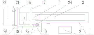
Fig. 1 is a front view of a feed feeding device of the present invention;
fig. 2 is a top view of the feed feeding device of the present invention;
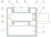
fig. 3 is a sectional view of the internal structure of the hollow trough body of the feed feeding device of the present invention.
In the figure: 1-hollow groove body, 2-control box, 3-material groove opening, 4-baffle, 5-blanking pipe, 6-recovery box, 7-scraper, 8-detection camera, 9-roller shaft, 10-driving motor, 11-gear, 12-chain, 13-bottom belt, 14-baffle belt, 15-mounting groove, 16-bracket, 17-hopper, 18-driving shaft, 19-driving wheel group, 20-driving sheet, 21-sliding rail, 22-platform, 23-driving cylinder, 24-driving wheel, 25-belt and 26-belt box.
Detailed Description
In order to facilitate understanding for those skilled in the art, the present invention will be further described with reference to the accompanying drawings.
A feed feeding device as shown in fig. 1-3, comprising a hollow trough body 1, wherein a control box 2 is arranged on one side of the hollow trough body 1, a material slot 3 is arranged on the hollow trough body 1, a baffle 4 is fixedly arranged around the material slot 3, a conveying mechanism matched with the material slot 3 is arranged below the baffle 4, one end of the hollow trough body 1 is connected with a material storage mechanism, a transmission mechanism is arranged between the material storage mechanism and the conveying mechanism for connection, a blanking pipe 5 is arranged between the material storage mechanism and the material slot 3 for communication, a recovery box 6 matched with the conveying mechanism is arranged at one end of the hollow trough body 1 far away from the material storage mechanism, a scraper 7 matched with the conveying mechanism is arranged on the hollow trough body 1 above the recovery box 6, a detection camera 8 matched with the conveying mechanism is arranged on the baffle 4 close to one end of the material slot 3 of the recovery box 6, the control box 2 is respectively electrically connected with the material storage mechanism, the conveying mechanism and the detection camera 8.
The conveying mechanism comprises a plurality of roller shafts 9 which are distributed in a linear array manner and are rotatably installed in the hollow groove body 1, one end, close to the recovery box 6, of each roller shaft 9 penetrates through the hollow groove body 1 and is connected with a driving motor 10, two ends of each roller shaft 9 in the hollow groove body 1 are connected with gears 11, the gears 11 are connected through chains 12, the roller shafts 9 are connected through a conveying belt in a wrapping manner, and the driving motors 10 are electrically connected with the control box 2; the conveying belt comprises a bottom belt 13 matched with the roller shaft 9, corrugated baffle belts 14 are arranged on two sides of the bottom belt 13 perpendicular to the moving direction of the conveying belt, and the baffle belts 14 and the bottom belt 13 are both made of composite rubber materials and are formed in a one-step processing mode; one end, close to the conveying belt, of the baffle 4 arranged in the material slot opening 3 along the direction parallel to the moving direction of the conveying belt is provided with an installation groove 15 matched with the baffle belt 14; the material storage mechanism comprises a support 16, a hopper 17 is fixedly mounted on one side of the support 16, the blanking pipe 5 is fixedly mounted below the hopper 17, a driving shaft 18 is arranged at the bottom of the hopper 17, a plurality of driving pieces 20 which are uniformly distributed are arranged on the driving shaft 18, the driving pieces 20 are matched with the blanking pipe 5, one end of the driving shaft 18 penetrates through the hopper 17 and is connected with the transmission mechanism, a sliding rail 21 is arranged on the other side of the support 16, a platform 22 capable of sliding freely is arranged on the sliding rail 21, the platform 22 is connected with a driving cylinder 23, the driving cylinder 23 is fixedly mounted on the support 16, and the driving cylinder 23 and a blanking motor are both electrically connected with the control box 2; the transmission mechanism comprises a driving wheel 24 fixedly arranged on the driving motor 10 and a driving wheel set 19 fixedly arranged at one end of a driving shaft 18 penetrating through the hopper 17, and the driving wheel 24 is in transmission connection with the driving wheel set 19; the driving wheel set 19 comprises a plurality of driving wheels with different diameters, and belts 25 with different diameters are arranged between the driving wheels and the driving wheel 24 for connection; the bracket 16 is provided at one side thereof with a belt case 26 for receiving the belts 25 of different diameters.
When the utility model works, firstly, the control box 2 is used for setting the feed adding time, then the worker pours the stirred feed into the storage box, then the storage box is moved to the feed feeding device, then the worker places the storage box on the platform 22, then the control box 2 is used for controlling the driving cylinder 23 to work, the driving cylinder 23 is used for pushing the platform 22 to move upwards along the slide rail 21 so as to lift the height of the storage box, when the storage box reaches the designated height, the worker pours the feed in the storage box into the hopper 17, then the control box 2 is used for controlling the driving cylinder 23 to reset so as to finish the feed feeding, when the time reaches the feed feeding time set by the control box 2, the control box 2 is used for controlling the driving motor 10 to work, and the driving wheel 24 and the driving wheel set 19 are connected through the belt 25, the driving motor 10 drives the driving shaft 18 to rotate, the driving shaft 18 drives the driving sheet 20 to rotate, the driving sheet 20 pushes the feed in the hopper 17 to be injected into the feed slot opening 3 of the hollow trough body 1 through the discharging pipe 5, meanwhile, under the cooperation of the chain 12 and the gear 11, the driving motor 10 drives the roller shaft 9 to rotate, the rotating roller shaft 9 drives the conveying belt to rotate, the feed remained in the feed slot opening 3 enters the hollow trough body 1 under the driving of the conveying belt and is gathered in the recycling box 6 under the action of self gravity and the scraper 7, meanwhile, the feed falling from the discharging pipe 5 can be uniformly distributed on the conveying belt in the feed slot opening 3, so that the residual feed and the newly fed feed are separated, and the feeding of the feed is completed, the detection camera 8 transmits the position information of the feed on the conveying belt to the control box 2, so that the newly thrown feed is prevented from being directly guided into the recovery box 6 by the conveying belt; according to different types of feed put into the hopper 17, different belts 25 in the belt box 26 are selected to connect the driving wheel 24 with corresponding driving wheels in the driving wheel set 19, so that the purpose of adjusting the feeding speed of the hopper 17 is achieved.
The foregoing is merely exemplary and illustrative of the structure of the invention, and various modifications, additions and substitutions as described in the detailed description may be made by those skilled in the art without departing from the structure or exceeding the scope of the invention as defined in the claims.
Claims (8)
1. The utility model provides a fodder feeding device, characterized by, includes the cavity cell body, cavity cell body one side is equipped with the control box, be equipped with the notch on the cavity cell body, fixed mounting has the baffle all around the notch, the baffle below install with notch matched with conveying mechanism, cavity cell body one end is connected with storage mechanism, be equipped with drive mechanism between storage mechanism and the conveying mechanism and be connected, be equipped with the unloading pipe intercommunication between storage mechanism and the notch, keep away from in the cavity cell body the one end of storage mechanism be equipped with conveying mechanism matched with collection box, the collection box top be equipped with on the cavity cell body with conveying mechanism matched with scraper blade, be close to the collection box material notch one end be equipped with on the baffle with conveying mechanism matched with detects the camera, the control box respectively with storage mechanism, conveyer, the control box, The conveying mechanism is electrically connected with the detection camera.
2. A fodder feeding device according to claim 1, characterized in that the conveying mechanism includes a plurality of rollers rotatably mounted in the hollow tank in a linear array distribution, one end of the roller near the recycling bin passes through the hollow tank and is connected with a driving motor, two ends of the roller in the hollow tank are connected with gears, a chain is arranged between the gears for connection, a conveying belt is arranged between the rollers for cladding connection, and the driving motor is electrically connected with the control box.
3. The feed feeding device as claimed in claim 2, wherein the conveyor includes a bottom belt engaged with the roller shaft, wherein corrugated blocking belts are provided on both sides of the bottom belt perpendicular to the moving direction of the conveyor, and the blocking belts and the bottom belt are formed by one-time processing of a composite rubber material.
4. A feed delivery device as claimed in claim 3 wherein the end of the said retaining plate adjacent the said conveyor belt and parallel to the direction of movement of the said conveyor belt within the said chute opening is provided with an attachment slot for engagement with the said retaining belt.
5. The feed feeding device according to claim 2, wherein the storage mechanism comprises a support, a hopper is fixedly mounted on one side of the support, the feeding pipe is fixedly mounted below the hopper, a driving shaft is arranged at the bottom of the hopper, a plurality of driving pieces are uniformly distributed on the driving shaft, the driving pieces are matched with the feeding pipe, one end of the driving shaft penetrates through the hopper and is connected with the transmission mechanism, a sliding rail is arranged on the other side of the support, a platform capable of freely sliding is arranged on the sliding rail, a driving cylinder is connected with the platform, the driving cylinder is fixedly mounted on the support, and the driving cylinder is electrically connected with the control box.
6. A feed delivery apparatus as claimed in claim 5 wherein the drive means comprises a drive wheel fixedly mounted on the drive motor and a drive wheel assembly fixedly mounted on one end of a drive shaft passing through the hopper, the drive wheel and drive wheel assembly being in driving connection.
7. A feed delivery device as claimed in claim 6 wherein the drive wheel assembly includes a plurality of drive wheels of different diameters, the drive wheels being connected to the drive wheels by belts of different diameters.
8. A feed delivery device as claimed in claim 7 wherein a belt cassette for receiving belts of different diameters is provided on one side of the support.
Priority Applications (1)
| Application Number | Priority Date | Filing Date | Title |
|---|---|---|---|
| CN202020224610.0U CN211983205U (en) | 2020-02-28 | 2020-02-28 | Fodder feeding device |
Applications Claiming Priority (1)
| Application Number | Priority Date | Filing Date | Title |
|---|---|---|---|
| CN202020224610.0U CN211983205U (en) | 2020-02-28 | 2020-02-28 | Fodder feeding device |
Publications (1)
| Publication Number | Publication Date |
|---|---|
| CN211983205U true CN211983205U (en) | 2020-11-24 |
Family
ID=73424614
Family Applications (1)
| Application Number | Title | Priority Date | Filing Date |
|---|---|---|---|
| CN202020224610.0U Expired - Fee Related CN211983205U (en) | 2020-02-28 | 2020-02-28 | Fodder feeding device |
Country Status (1)
| Country | Link |
|---|---|
| CN (1) | CN211983205U (en) |
Cited By (1)
| Publication number | Priority date | Publication date | Assignee | Title |
|---|---|---|---|---|
| CN115530084A (en) * | 2022-08-29 | 2022-12-30 | 宁夏众虎科技股份有限公司 | Pasture intelligent feeding system and control method |
-
2020
- 2020-02-28 CN CN202020224610.0U patent/CN211983205U/en not_active Expired - Fee Related
Cited By (1)
| Publication number | Priority date | Publication date | Assignee | Title |
|---|---|---|---|---|
| CN115530084A (en) * | 2022-08-29 | 2022-12-30 | 宁夏众虎科技股份有限公司 | Pasture intelligent feeding system and control method |
Similar Documents
| Publication | Publication Date | Title |
|---|---|---|
| CN209814936U (en) | High temperature stirred tank furnace material feeding unit | |
| CN211983205U (en) | Fodder feeding device | |
| CN206720163U (en) | It is a kind of to circulate swing feeder and use its apparatus for drying | |
| CN112246335A (en) | Fertilizer is made and is retrieved crushing screening granulation all-in-one with rubbish | |
| CN211139709U (en) | Intelligent coiling line for traditional Chinese medicine decoction pieces | |
| CN108609405A (en) | A kind of charging device for coating material production | |
| CN211607813U (en) | Fodder feeding device | |
| CN106943910B (en) | Fertilizer distributor | |
| CN210202910U (en) | Automatic feeding and feeding system for chicken farm | |
| CN213848179U (en) | Cattle feed delivery device | |
| CN202738590U (en) | Feed delivery trough | |
| CN211590721U (en) | Self-control concrete conveying and processing device | |
| CN211379266U (en) | Chicken farm feeds and eats device | |
| CN202481740U (en) | Automatic feeding machine of tea leaves | |
| CN211005173U (en) | Fertilizer production is with fermentation distributing device | |
| CN113758173A (en) | Grain tedder | |
| CN112848088A (en) | Raw material conveying device for production of vacuum heat insulation boards | |
| CN220733938U (en) | Sheep hurdle is with clearance car | |
| CN219620211U (en) | Waste battery treatment feeding equipment | |
| CN211482373U (en) | Hand-held cow house manure cleaning machine | |
| CN212299869U (en) | A safe automatic feeding device for drying-machine | |
| CN219205611U (en) | Black soldier fly modularization breeding equipment | |
| CN217837083U (en) | Automatic feeding device | |
| CN214191486U (en) | Feeding device suitable for breeding big silkworms | |
| CN219669327U (en) | Fertilizer conveyer |
Legal Events
| Date | Code | Title | Description |
|---|---|---|---|
| GR01 | Patent grant | ||
| GR01 | Patent grant | ||
| CF01 | Termination of patent right due to non-payment of annual fee | ||
| CF01 | Termination of patent right due to non-payment of annual fee |
Granted publication date: 20201124 |