CN211524389U - Novel structure of lock tongue - Google Patents
Novel structure of lock tongue Download PDFInfo
- Publication number
- CN211524389U CN211524389U CN201921421014.5U CN201921421014U CN211524389U CN 211524389 U CN211524389 U CN 211524389U CN 201921421014 U CN201921421014 U CN 201921421014U CN 211524389 U CN211524389 U CN 211524389U
- Authority
- CN
- China
- Prior art keywords
- lock
- bolt
- main
- assembly
- latch
- Prior art date
- Legal status (The legal status is an assumption and is not a legal conclusion. Google has not performed a legal analysis and makes no representation as to the accuracy of the status listed.)
- Active
Links
Images


Landscapes
- Lock And Its Accessories (AREA)
Abstract
The utility model discloses a novel structure of a lock tongue, which comprises a main lock component and a latch bolt component; the primary lock assembly comprises a first moving member, at least one primary lock tongue and a connecting plate, and the latch bolt assembly can move to the first moving member; the latch bolt component comprises a second moving part and a latch bolt; the latch bolt component is movably arranged on the first moving part through the second moving part. Through the arrangement of the main lock assembly and the oblique bolt assembly, the main lock assembly comprises a first moving member, at least one main lock bolt and a connecting plate, and the oblique bolt assembly comprises a second moving member and an oblique bolt; the second moving piece is movably arranged on the first moving piece, and when the lock is opened and closed, the first moving piece is moved to simultaneously extend or retract the main lock tongue and the latch bolt; compared with the prior structure that the main bolt and the latch bolt cannot be extended out or retracted back simultaneously, the time for opening and closing the lock can be further reduced, the waiting time of a user is shortened, and the experience of the user is improved.
Description
Technical Field
The utility model belongs to the technical field of the tool to lock structure technique and specifically relates to indicate a novel structure of spring bolt.
Background
With the development of society, the requirements of door locks on safety and convenience are increasing day by day. The door lock generally has two opening modes, namely an electric unlocking mode; a mechanical unlocking mode. The electric unlocking mode mainly comprises an electronic lock head, a magnetic card, a TM card (button key), an ID induction card, a wireless remote control, a computer door lock control system, a fingerprint, a biological identification technology that a clutch is usually arranged between the lock part and the electric unlocking part and then an eye mask is connected with an unlocking gear, and the like. The mechanical unlocking mode is that a mechanical key matched with the anti-theft lock head is inserted into the exposed or hidden anti-theft lock head to unlock the lockset. The mechanical opening mode can be used in case of electrical failure or emergency special condition.
In the prior art, a main bolt and an oblique bolt of the electromechanical lock capable of integrating an electrical switch lock and a mechanical switch lock are respectively connected with a motor and a lock cylinder through connecting parts, and the main bolt and the oblique bolt cannot be extended out or retracted into the main bolt and the oblique bolt simultaneously no matter the electromechanical switch lock or the mechanical switch lock; therefore, the locking and unlocking time is caused, and the user often needs to wait for a long time when using the lock, so that the user experience is poor.
SUMMERY OF THE UTILITY MODEL
In view of the above, the present invention provides a novel structure of a lock tongue, which is reasonable in structure arrangement, improves the structure of a main lock tongue and a latch bolt, and can simultaneously extend or retract the main lock tongue and the latch bolt when the lock is opened or closed; therefore, the waiting time is reduced, and the user experience is improved.
In order to achieve the above purpose, the utility model adopts the following technical scheme:
a novel structure of a lock bolt comprises a main lock component and a latch bolt component; the primary lock assembly comprises a first moving member, at least one primary lock tongue and a connecting plate, and the latch bolt assembly can move to the first moving member; the latch bolt component comprises a second moving part and a latch bolt; the latch bolt component is movably arranged on the first moving part through the second moving part.
As a preferred embodiment: the main bolt comprises a middle bolt group, an upper end bolt group and a lower end bolt group, and the middle bolt group, the upper end bolt group and the lower end bolt group are all integrally formed on the side surface of the first moving member.
As a preferred embodiment: the first moving piece is provided with a window which is positioned between the middle bolt group and the upper end bolt group; the second moving part is movably arranged in the window.
As a preferred embodiment: the lifting device further comprises a top and bottom rod which is arranged at two ends of the first moving piece.
As a preferred embodiment: the connecting plate is provided with a concave position for shifting and an elastic block; the bullet piece is movably arranged in the connecting plate, and the tail end of the bullet piece extends into the concave position.
As a preferred embodiment: the lock shell is internally provided with an assembly space and at least provided with a main lock hole and an inclined tongue hole; the moving piece moves the main lock tongue to extend out of the main lock hole to close the lock or retract to open the lock; the latch bolt is moved by the second moving piece or the first moving piece and extends out of the latch bolt hole to close the lock or retracts to open the lock.
As a preferred embodiment: the main lock assembly is also provided with a movable connecting rod, and the connecting rod is provided with a limited end and a first poking end;
the second moving part is provided with a limited end, and the limited end can be selectively limited in the limited position;
the latch bolt shifting plate is provided with a first shifting part which can be selectively connected with a first shifting end.
Compared with the prior art, the utility model obvious advantage and beneficial effect have, particularly, can know by above-mentioned technical scheme: through the arrangement of the main lock assembly and the oblique bolt assembly, the main lock assembly comprises a first moving member, at least one main lock bolt and a connecting plate, and the oblique bolt assembly comprises a second moving member and an oblique bolt; the second moving piece is movably arranged on the first moving piece, and when the lock is opened and closed, the first moving piece is moved to simultaneously extend or retract the main lock tongue and the latch bolt; compared with the prior structure that the main bolt and the latch bolt cannot be extended out or retracted back simultaneously, the time for opening and closing the lock can be further reduced, the waiting time of a user is shortened, and the experience of the user is improved.
To illustrate the structural features and functions of the present invention more clearly, the present invention will be described in detail with reference to the accompanying drawings and specific embodiments.
Drawings
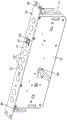
Fig. 1 is a schematic view of an electromechanical lock according to a preferred embodiment of the present invention.
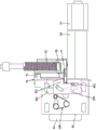
Fig. 2 is a schematic diagram of an internal structure of an electromechanical lock according to a preferred embodiment of the present invention.
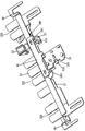
Fig. 3 is a perspective view of the main lock assembly and the latch member of the preferred embodiment of the present invention.
Fig. 4 is a front view of the main lock assembly and the latch member of the preferred embodiment of the present invention.
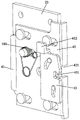
Fig. 5 is a schematic perspective view of a clutch assembly according to a preferred embodiment of the present invention.
Fig. 6 is another angular schematic of fig. 5.
Fig. 7 is an exploded view of fig. 5.
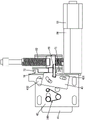
Fig. 8 is a schematic view of the clutch assembly and the driving assembly according to the preferred embodiment of the present invention.
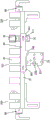
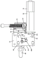
Fig. 9 is a schematic structural diagram of the main bolt assembly, the latch bolt assembly and the lock cylinder according to the preferred embodiment of the present invention.
Fig. 10 is a schematic view of the driving assembly toggle clutch assembly according to the preferred embodiment of the present invention.
Fig. 11 is a schematic view of the lock cylinder shifting clutch assembly of the preferred embodiment of the present invention being disengaged from the driving assembly.
The attached drawings indicate the following:
10. lock shell 11 and bottom shell
12. Face shell 13, lock panel
131. Main lock hole 132, oblique tongue hole
14. Assembly space 20, primary lock assembly
21. First moving part 211, window
22. Main bolt 221 and middle bolt set
222. Upper end bolt group 223 and lower end bolt group
23. Connection plate 231, concave position
232. Bullet 2321, sixth cylinder
233. First column 234, second column
235. Third cylinder 236, eighth hole
24. Connecting rod 241, constrained end
242. A first toggle end 243 and a second toggle end
30. Latch bolt assembly 31 and second moving part
311. Limited 32, oblique tongue
40. Clutch assembly 41 and clutch plate
411. First hole 42, main lock dial plate
422. Second hole 423 and third hole
424. Fourth hole 425 and fifth hole
426. Fifth column 43, inclined tongue pulling plate
431. Second gap 432 and first toggle part
433. Sixth hole 434, seventh hole
44. Swing arm 441, circular hole
442. Fourth cylinder 50, drive assembly
51. Motor 52 and screw rod
53. Shifting block 60 and lock cylinder
61. Shifting fork 70 and inductive switch
71. First sensing point 72 and second sensing point
80. Control unit 90, world pole
100. A torsion spring.
Detailed Description
Please refer to fig. 1 to 11, which show the specific structure of the preferred embodiment of the present invention, which is a novel structure of a lock tongue, and the novel structure of the lock tongue is applied to a mechanical lock or an electromechanical lock mainly through a main lock component and a latch bolt component movably disposed on the main lock component, and the main lock tongue and the latch bolt can be simultaneously extended or retracted to realize the on-off lock, thereby improving the efficiency of the on-off lock and reducing the waiting time of a user; in this document, an electromechanical lock is taken as an example, but not limited thereto.
The electromechanical lock comprises a lock housing 10, a main lock assembly 20, a latch assembly 30, a clutch assembly 40, a drive assembly 50 and a lock cylinder 60.
The lock case comprises a bottom shell 11, a face shell 12 and a lock panel 13, the bottom shell 11, the face shell 12 and the lock panel 13 surround to form an assembly space 14, and the lock panel 13 is at least provided with a main lock hole 131 and a latch hole 132. In the present embodiment, the main lock assembly 20 is mounted to the fitting space 14; the main lock assembly 20 comprises a first moving member 21, at least one main bolt 22 and a connecting plate 23, wherein the moving member 21 moves the main bolt 22 to extend out of the main lock hole 131 for locking or retract back for unlocking; the main bolt 22 includes a middle bolt group 221, an upper bolt group 222 and a lower bolt group 223, and the middle bolt group 221, the upper bolt group 222 and the lower bolt group 223 are integrally formed on the side surface of the first moving member 21. The safety factor of the electromechanical lock can be enhanced by the three sets of lock tongues; and integrated into one piece locates first moving member 21, and, by first moving member 21 removal, can make spring bolt 22 stretch out or retract more steadily, stability is good. The connecting plate 23 is provided with a concave position 231 for shifting the shifting fork 61 and an elastic block 232 for preventing the shifting fork 61 from being clamped on the connecting plate 23; the elastic block 232 is movably arranged on the connecting plate 23, and the tail end of the elastic block 232 extends into the concave position 231. And, a top and bottom rod 90 is provided at both ends of the first moving member.
The latch bolt assembly 30 is movably arranged on the first moving part 21; the latch bolt assembly 30 comprises a second moving member 31 and a latch bolt 32, wherein the latch bolt 32 is moved by the second moving member 31 or the first moving member 21 to extend out of the latch bolt hole 132 to close the lock or retract to open the lock. In this embodiment, the first moving member 21 has a window 211, the window 211 is located between the middle latch tongue set 221 and the upper latch tongue set 222, and the second moving member 31 is movably disposed in the window 211. The bolt assembly 30 is arranged on the main lock assembly 20, so that the synchronous extension or retraction of the main bolt 22 and the bolt 23 can be realized; compared with the prior electromechanical lock which can not synchronously extend or retract the main bolt 22 and the latch bolt 23, the time control of the locking and unlocking can be made shorter, and the working efficiency of the locking and unlocking is improved; the user can reduce the time of waiting for opening and closing the lock when using, and the use is convenient.
The clutch assembly 40 is arranged on the connecting plate 23; the clutch assembly 40 comprises a clutch plate 41, a main lock dialing plate 42 and a latch dialing plate 43, wherein the clutch plate 41 can drive the main lock dialing plate 42 and the latch dialing plate 43 to move. In this embodiment, the clutch plate 41 is movably mounted to the connecting plate 23, and the main latch dial 42 and the latch dial 43 are sequentially movably stacked on the clutch plate 41. The clutch assembly 40 further comprises a swing arm 44, and the swing arm 44 is rotatably mounted on the connecting plate 23; one end of the swing arm 44 is connected with the clutch plate 41, the other end is connected with the main lock dialing plate 42, and the clutch plate 41 moves to enable the swing arm 44 to swing so as to drive the main lock dialing plate 42 and the latch bolt dialing plate 43 to be disconnected with the dialing block 53.
Referring to fig. 5, 6 and 7, in the present embodiment, the connecting plate 23 is provided with a first column 233, a second column 234 and a third column 235; the clutch plate 41 is provided with a first hole 411, and the clutch plate 41 is movably arranged on the connecting plate 23 through the first hole 411 and the first column 233. The main lock dialing plate 42 is provided with a plurality of second holes 422, the number of the second columns 234 of the connecting plate 23 is the same as that of the second holes 422, and the second holes 422 and the second columns 234 correspond to each other one by one, and the main lock dialing plate 42 is movably assembled on the connecting plate 23 through the second holes 422 and the second columns 234; and, the main striking plate 42 is further provided with a third hole 423, a fourth hole 424 and a fifth hole 425, the third hole 423 corresponding to the first hole 411, and the first cylinder 233 can be extended to the front of the third hole 423. The swing arm 44 has a circular hole 441 at the center, and the swing arm 44 is swingably mounted in the third cylinder 235 through the circular hole 441; the end of the swing arm 44 connected to the main striking plate 42 is provided with a fourth cylinder 442, the fourth cylinder 442 is inserted into the fifth hole 425, and the third cylinder 235 is confined in the fourth hole 424. The latch pulling plate 43 is provided with a sixth hole 433 and a seventh hole 434, and the seventh hole 434 is an arc-shaped guide hole; main deadbolt dialing plate 42 has two fifth posts 426 with sixth aperture 433 and seventh aperture 434 being confined within respective fifth posts 426. The bullet block 232 is provided with a sixth cylinder 2321, an eighth hole 236 is formed on the connecting plate 23, and the bullet block 232 is movably assembled to the connecting plate 23 through the sixth cylinder 2321 and the eighth hole 236. Further, a torsion spring 100 is provided between the spring block 232 and the connecting plate 23 and between the main lock dial plate 42 and the clutch plate 41, and elastic potential energy is provided by the torsion spring 100 to provide an elastic force therebetween.
The driving assembly 50 includes a motor 51, a lead screw 52 and a shifting block 53 movably sleeved on the lead screw 52, and the main lock shifting plate 42 and the latch shifting plate 43 can be selectively connected with the shifting block 53. Specifically, the main latch pulling plate 42 has a first notch 421, the latch pulling plate 43 has a second notch 431, and the width of the first notch 421 is greater than that of the second notch 431; the shifting block 53 can selectively extend into the first notch 421 and the second notch 431. Because the width of the first notch 421 is greater than that of the second notch 431, when the shifting block 53 moves to abut against the same side face of the first notch 421 and the second notch 431, the main lock shifting plate 42 and the latch shifting plate 43 can be shifted simultaneously; or the moving block 53 moves to abut against the second gap 431 and only moves the latch poking plate 43 when not abutting against the first gap 421. For example, if the shifting block 53 moves by one centimeter until the latch plate 43 is shifted to eject the latch 32, only the latch 32 is shifted each time, and only the shifting block 53 moves by one centimeter to shift the latch plate 43, but not the main latch plate 42. The motor 51 is connected with the screw rod 52 through a reduction gearbox 54, and the reduction gearbox 54 is provided with an input end and an output end; the motor 51 is connected to the input end, and one end of the screw rod 52 is vertically connected to the output end.
Illustratively, as shown in fig. 3 and 4, the main lock assembly 20 is further provided with a movable connecting rod 24, the connecting rod 24 having a restricted end 241, a first dial end 242 and a second dial end 243. The second moving member 31 has a restricted portion 311, and the restricted end 241 can be selectively restricted in the restricted portion 311. The latch pulling plate 43 has a first pulling portion 432, and the first pulling portion 432 is selectively connected to the first pulling end 242; the shifting fork 61 can be selectively connected with the second shifting end 243; when the latch bolt dialing plate 43 dials the first dialing end 242 or the shifting fork 61 dials the second dialing end 243, the connecting rod 24 can move, and then the limited end 242 is separated from the limited position 311, and the second moving member 31 moves to extend the latch bolt 32. Here, it should be noted that a torsion spring 100 is also installed beside the second moving member 31, and the second moving member 31 can be moved by the elastic potential energy of the torsion spring 100.
The lock core 60 has a shift fork 61, and when the shift fork 61 is shifted, both the main lock shifting plate 42 and the latch bolt shifting plate 43 can be disconnected from the shifting block 53, and simultaneously shift the main lock bolt 22, the latch bolt 32 or only the latch bolt 32. In the present embodiment, the key cylinder 60 is disposed on the left side of the clutch assembly 40, and the driving assembly 50 is disposed on the right side of the clutch assembly 40.
Further comprises an inductive switch 70 and a control unit 80, wherein the inductive switch 70 is arranged in the assembly space 14 and is positioned beside the screw rod 52; the inductive switch 70 has a first inductive point 71 and a second inductive point 72; the control unit comprises a control circuit board and a chip arranged on the control circuit board. The control unit 80 is respectively connected to the inductive switch 70 and the motor 51 to control the operating states of the corresponding components.
Detailed description the working principle of the utility model is as follows: the electromechanical lock has two working modes; the first is an electric switch lock, which is powered by the driving assembly 50; the second is a mechanical switch lock, which is a mode of manually shifting a lock core; it is explained here that in the normal state of the electromechanical lock, both the main bolt and the latch bolt are retracted into the corresponding lock holes.
Referring to fig. 8 and 10, in a first mode, firstly, the motor 51 of the driving assembly 50 works to rotate the screw rod 52, the shifting block 53 moves along with the rotation of the screw rod 52 and shifts the latch lifting plate 43, and the latch lifting plate 43 shifts the connecting rod 24 to be separated from the second moving member 31, so that the latch 32 is ejected; then, after the movable door is closed, the shifting block 53 continues to move to shift the main lock shifting plate 42 so as to drive the first movable 21 to move and extend out of the main lock tongue 22, the shifting block 53 stops moving after moving to the second induction point 72 to complete locking, and at this time, the main lock tongue 22 is in a completely extended state; finally, the motor rotates reversely to drive the shifting block 53 to move back, so as to drive the main bolt 22 and the latch bolt 32 to retract simultaneously to complete unlocking, and the shifting block 53 stops moving after moving to the first sensing point 71.
Referring to fig. 9 and 11, in the second mode, first, the shifting fork 61 is reversely pressed against the clutch plate 41 and is moved to simultaneously disengage the main lock shifting plate 42 and the latch shifting plate 43 from the block 53; then, the shifting fork 61 is further shifted to enable the connecting plate 23 to simultaneously extend out of the main bolt 22 and the latch bolt 32 to close the lock; the forward rotation fork 61 can simultaneously pull the link plate 23 while retracting the main bolt 22 and the latch bolt 32 to unlock. Of course, when both the main bolt 22 and the latch tongue 32 are retracted, the forward rotation fork 61 can also be used to pull only the latch tongue 32 to eject.
The utility model discloses a design focus lies in: through the arrangement of the main lock assembly 20 and the latch bolt assembly 30, the main lock assembly 20 comprises a first moving part 21, at least one main latch bolt 22 and a connecting plate 23, and the latch bolt assembly 30 comprises a second moving part 31 and a latch bolt 32; the second moving part 31 can be movably arranged on the first moving part 21, and when the lock is opened and closed, the first moving part 21 is moved to simultaneously extend or retract the main bolt 22 and the latch bolt 32; compared with the prior structure that the main bolt and the latch bolt cannot be extended out or retracted back simultaneously, the time for opening and closing the lock can be further reduced, the waiting time of a user is shortened, and the experience of the user is improved.
The above description is only a preferred embodiment of the present invention, and is not intended to limit the technical scope of the present invention, so that any slight modifications, equivalent changes and modifications made by the technical spirit of the present invention to the above embodiments are all within the scope of the technical solution of the present invention.
Claims (7)
1. The utility model provides a novel structure of spring bolt which characterized in that: comprises a main lock assembly (20) and a latch bolt assembly (30); the master lock assembly (20) comprises a first moving member (21), at least one master bolt (22) and a connecting plate (23), and the latch bolt assembly (30) can move to the first moving member (21); the latch bolt component (30) comprises a second moving part (31) and a latch bolt (32); the latch tongue assembly (30) is movably arranged on the first moving part (21) through a second moving part (31).
2. The novel structure of a lock tongue of claim 1, characterized in that: the main bolt (22) comprises a middle bolt group (221), an upper end bolt group (222) and a lower end bolt group (223), and the middle bolt group (221), the upper end bolt group (222) and the lower end bolt group (223) are all integrally formed on the side face of the first moving member (21).
3. The novel structure of a lock tongue of claim 1, characterized in that: the first moving part (21) is provided with a window (211), and the window (211) is positioned between the middle bolt group (221) and the upper bolt group (222); the second moving part (31) is movably arranged in the window (211).
4. The novel structure of a lock tongue of claim 1, characterized in that: further comprises a top and bottom rod (90), and the top and bottom rod (90) is arranged at two ends of the first moving part (21).
5. The novel structure of a lock tongue of claim 1, characterized in that: the connecting plate (23) is provided with a concave position (231) for shifting and an elastic block (232); the elastic block (232) is movably arranged on the connecting plate (23), and the tail end of the elastic block (232) extends into the concave position (231).
6. The novel structure of a lock tongue of claim 1, characterized in that: also includes: a lock shell (10), an assembly space (14) is arranged in the lock shell (10), and at least a main lock hole (131) and an oblique tongue hole (132) are arranged on the lock shell (10); the moving piece (21) moves the main bolt (22) to extend out of the main lock hole (131) to close the lock or retract to open the lock; the latch bolt (32) is moved by the second moving part (31) or the first moving part (21) to extend out of the latch bolt hole (132) to close the lock or retract to open the lock.
7. The novel structure of a lock tongue of claim 6, characterized in that: the main lock assembly (20) is further provided with a movable connecting rod (24), and the connecting rod (24) is provided with a limited end (241) and a first poking end (242);
the second moving part (31) is provided with a limited end (311), and the limited end (241) can be selectively limited in the limited end (311).
Priority Applications (1)
| Application Number | Priority Date | Filing Date | Title |
|---|---|---|---|
| CN201921421014.5U CN211524389U (en) | 2019-08-29 | 2019-08-29 | Novel structure of lock tongue |
Applications Claiming Priority (1)
| Application Number | Priority Date | Filing Date | Title |
|---|---|---|---|
| CN201921421014.5U CN211524389U (en) | 2019-08-29 | 2019-08-29 | Novel structure of lock tongue |
Publications (1)
| Publication Number | Publication Date |
|---|---|
| CN211524389U true CN211524389U (en) | 2020-09-18 |
Family
ID=72439458
Family Applications (1)
| Application Number | Title | Priority Date | Filing Date |
|---|---|---|---|
| CN201921421014.5U Active CN211524389U (en) | 2019-08-29 | 2019-08-29 | Novel structure of lock tongue |
Country Status (1)
| Country | Link |
|---|---|
| CN (1) | CN211524389U (en) |
Cited By (1)
| Publication number | Priority date | Publication date | Assignee | Title |
|---|---|---|---|---|
| CN110388136A (en) * | 2019-08-29 | 2019-10-29 | 金华市博弘汇智能科技有限公司 | Screw rod shifting block drive-type lock construction |
-
2019
- 2019-08-29 CN CN201921421014.5U patent/CN211524389U/en active Active
Cited By (2)
| Publication number | Priority date | Publication date | Assignee | Title |
|---|---|---|---|---|
| CN110388136A (en) * | 2019-08-29 | 2019-10-29 | 金华市博弘汇智能科技有限公司 | Screw rod shifting block drive-type lock construction |
| CN110388136B (en) * | 2019-08-29 | 2024-05-10 | 深圳市弘博汇科技有限公司 | Screw rod shifting block driving type lock structure |
Similar Documents
| Publication | Publication Date | Title |
|---|---|---|
| CN108756471B (en) | High-strength safe intelligent lock cylinder | |
| CN211058490U (en) | Electromechanical lock convenient for switching bolt driving mode | |
| CN211058492U (en) | Electromechanical lock | |
| CN110359776B (en) | Electromechanical lock | |
| CN211524389U (en) | Novel structure of lock tongue | |
| CN200985682Y (en) | Electric intelligent cabinet door lock | |
| CN201763077U (en) | Humanized counter locking intelligent lock | |
| CN106948671A (en) | A kind of intelligent case and bag fingerprint electronic lock | |
| CN211058474U (en) | Anti-locking structure of lock cylinder and lock tongue | |
| CN211058491U (en) | Screw rod shifting block driving type lock structure | |
| CN211058469U (en) | Improved clutch assembly of lock | |
| CN209761052U (en) | Electromechanical lock body | |
| CN110388136B (en) | Screw rod shifting block driving type lock structure | |
| CN102086718B (en) | Electronic lock hole protective device with electromagnetic clutch | |
| CN201065680Y (en) | Electronic key | |
| CN110219520B (en) | Intelligent lock double-insurance door opening structure | |
| CN212317676U (en) | Clutch device of motor lock body and motor lock body | |
| CN113202352A (en) | Full-automatic lock body | |
| CN209837953U (en) | Mechanical electronic fingerprint lock cylinder | |
| CN219281485U (en) | Full-automatic lock body | |
| CN220955098U (en) | Driving structure of full-automatic electronic lock body | |
| CN216866295U (en) | One-step electronic quick-unlocking lock | |
| CN218375875U (en) | Mute electric control lock body | |
| CN212002726U (en) | Automatic lock convenient to unlock | |
| CN210563850U (en) | Electronic lock with main lock tongue |
Legal Events
| Date | Code | Title | Description |
|---|---|---|---|
| GR01 | Patent grant | ||
| GR01 | Patent grant | ||
| TR01 | Transfer of patent right | ||
| TR01 | Transfer of patent right |
Effective date of registration: 20220815 Address after: 518000 East, 5th floor, building 501, xujingchang Industrial Park, No. 39, Haoye Road, Xinhe community, Fuhai street, Bao'an District, Shenzhen City, Guangdong Province Patentee after: SHENZHEN HOBERE TECHNOLOGY CO.,LTD. Address before: Wangda Road Industrial Zone, Baiyang Street, Wuyi County, Jinhua City, Zhejiang Province, 321000 Patentee before: Jinhua bohonghui Intelligent Technology Co.,Ltd. |