CN211427190U - Server circuit and mainboard based on Feiteng treater 2000+ - Google Patents
Server circuit and mainboard based on Feiteng treater 2000+ Download PDFInfo
- Publication number
- CN211427190U CN211427190U CN201921716732.5U CN201921716732U CN211427190U CN 211427190 U CN211427190 U CN 211427190U CN 201921716732 U CN201921716732 U CN 201921716732U CN 211427190 U CN211427190 U CN 211427190U
- Authority
- CN
- China
- Prior art keywords
- bmc
- signal
- rtc
- cpu
- sys
- Prior art date
- Legal status (The legal status is an assumption and is not a legal conclusion. Google has not performed a legal analysis and makes no representation as to the accuracy of the status listed.)
- Active
Links
- 238000006243 chemical reaction Methods 0.000 claims abstract description 28
- 230000008054 signal transmission Effects 0.000 claims abstract description 4
- 230000001133 acceleration Effects 0.000 abstract 1
- 238000010586 diagram Methods 0.000 description 8
- 238000004891 communication Methods 0.000 description 4
- 238000001514 detection method Methods 0.000 description 4
- 230000000694 effects Effects 0.000 description 4
- 230000006870 function Effects 0.000 description 4
- 238000000034 method Methods 0.000 description 4
- 230000001360 synchronised effect Effects 0.000 description 4
- 101100498818 Arabidopsis thaliana DDR4 gene Proteins 0.000 description 2
- 238000005034 decoration Methods 0.000 description 2
- 238000012986 modification Methods 0.000 description 2
- 230000004048 modification Effects 0.000 description 2
- 238000012545 processing Methods 0.000 description 2
- 239000000969 carrier Substances 0.000 description 1
- 238000013461 design Methods 0.000 description 1
- 238000011161 development Methods 0.000 description 1
- 230000002093 peripheral effect Effects 0.000 description 1
Images


Landscapes
- Power Sources (AREA)
Abstract
The embodiment of the utility model discloses 2000+ server circuit and mainboard based on Feiteng treater, including first control module, second control module, switching module, SYS _ RTC and BMC _ RTC; the first control module is used for reading the system hardware time of the SYS _ RTC, the second control module is also used for writing the system hardware time into the BMC _ RTC, the switching module is used for switching a first control module channel and a second control module channel, and the switching module is also used for level conversion in circuit signal transmission. When the circuit is plugged in a power supply and a power line, the BMC reads the system hardware time from the SYS _ RTC and uses the system hardware time as the BMS hardware time, and when a set-up key is pressed down and the circuit is started, the CPU reads the SYS _ RTC system hardware time so as to realize the synchronization of the system hardware time and the BMC hardware time. The embodiment of the utility model provides a problem that the PCIE resource can't support external equipment such as RAID card, HCA card, HBA card, FPGA acceleration card of a greater amount has still been solved.
Description
Technical Field
The utility model relates to a server mainboard technical field, concretely relates to server circuit and mainboard based on treater 2000+ soars.
Background
With the increasingly fierce competition in China and America, in order to reduce or even get rid of the dependence on processors of Intel, AMD and other American companies in China, the state pays more and more attention to the development of domestic CPUs, Feiteng is taken as one of the domestic processors, the latest processors of the Feiteng reach the leading level in the industry, and the Feiteng is widely applied to various industries such as storage, Internet and the like. At present, a Feiteng 2000+64 core processor (FT2000+ CPU) based on an ARM64 platform, which is proposed by Feiteng, can already support an 8-channel DDR4 memory, integrates two sets of PCIE X16 resources and one set of PCIE X1 resources, greatly improves the CPU operation performance, and simultaneously, Feiteng also issues a FT2000+ CPU male server mainboard based on the processor.
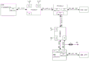
As shown in fig. 1, the server motherboard design scheme of the FT2000+ CPU male version mainly includes some external interfaces such as FT2000+ CPU, DDR4 memory, pex8632pcie2.0switch, BMC AST2300, CPLD, USB, and internet access.
The FT2000+ CPU and the BMC are respectively provided with independent clocks, and the time between the FT2000+ CPU and the BMC cannot be calibrated and unified, so that the problem that the system hardware time and the BMC hardware time are not synchronous is caused; the server motherboard of FT2000+ CPU has limited resources of PCIE X8, PCIE X16, and PCIE X1, and cannot support a large number of external devices such as RAID cards, HCA cards, HBA cards, and FPGA accelerator cards.
SUMMERY OF THE UTILITY MODEL
The embodiment of the utility model provides an in provide a server circuit and mainboard based on processor 2000+ soars to solve the asynchronous problem of system hardware time and BMC hardware time among the prior art, and the problem of external equipment such as RAID card, HCA card, HBA card, FPGA accelerator card that the PCIE resource can't support more.
The embodiment of the utility model discloses following technical scheme:
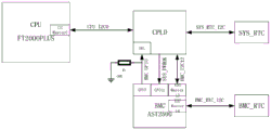
the utility model discloses a first aspect provides a 2000+ server circuit based on processor of soaring, including first control module, second control module, switching module, SYS _ RTC and BMC _ RTC, first control module connects the switching module, the second control module connects the switching module, the switching module is connected SYS _ RTC and BMC _ RTC;
the first control module is used for reading the system hardware time of the SYS _ RTC, the second control module is also used for writing the system hardware time into the BMC _ RTC, the switching module is used for switching a first control module channel and a second control module channel, and the switching module is also used for level conversion in the circuit signal transmission.
Further, the first control module comprises a CPU, a CPU _ I2C0 signal of the CPU is connected to the switching module, the second control module comprises a BMC, a BMC _ I2C12 signal, a BMC _ GPIO signal, and a SYS _ PWROK signal of the BMC are connected to the switching module, a BMC _ GPIO signal of the BMC is grounded through a resistor R1, and a BMC _ RTC _ I2C12 signal of the BMC is connected to the BMC _ RTC.
Further, the switching module comprises a CPLD, an input end of the CPLD is connected with a CPU _ I2C0 signal, a BMC _ I2C12 signal, a BMC _ GPIO signal and an SYS _ PWROK signal, and an output end of the CPLD is connected with the SYS _ RTC through an SYS _ RTC _ I2C signal.
Further, the switching module includes a first voltage conversion chip, a second voltage conversion chip and an I2C switching chip, an input end of the first voltage conversion chip is connected with a CPU _ I2C0 signal, an output end of the first voltage conversion chip is connected with a CPU _ I2C0_3.3V signal, an input end of the second voltage conversion chip is connected with a BMC _ I2C12 signal and a BMC _ GPIO signal, an output end of the second voltage conversion chip is connected with a BMC _ I2C12_3.3V signal, an input end of the I2C switching chip is connected with a CPU _ I2C0_3.3V signal and a BMC _ I2C12_3.3V signal, and an output end of the I2C switching chip is connected with the SYS _ RTC through a SYS _ RTC _ I2C signal.
Further, the circuit further comprises a PCIE expansion module, where the PCIE expansion module includes a first expansion chip and a second expansion chip, the first expansion chip is connected to the CPU, and the second expansion chip is connected to the CPU.
Further, the input end of the first expansion chip is connected with lane0-lane7 of the CPU PCIE0 controller, the output end of the first expansion chip is connected with a PCIE X8SLOT connector and/or a Slimline connector, the PCIE X8SLOT connector externally inserts a RAID card, an HCA card or an HBA card, and the Slimline connector is connected with an NVME hard disk.
Furthermore, the number of the PCIE X8SLOT connectors is 1-5, and the number of the Slimline connectors is 1-2.
Further, the input end of the second expansion chip is connected to lane8-lane15 of the CPU PCIE0 controller, the output end of the second expansion chip is connected to the gigabit network card through a PCIE2.0X8 bus, the output end of the second expansion chip is connected to the gigabit network card through a PCIE2.0X4 bus, the output end of the second expansion chip is connected to the USB controller or the BMC through a PCIE2.0X1 bus, and the output end of the second expansion chip is connected to the RAID controller through a PCIE2.0X2 bus.
The utility model discloses the second aspect provides a server mainboard based on treater 2000+ soars, the mainboard basis the circuit is realized.
The effects provided in the contents of the present invention are only the effects of the embodiments, not all the effects of the present invention, and one of the above technical solutions has the following advantages or advantageous effects:
1) the utility model discloses the switching module of circuit is used for the switching of first control module route and second control module route, and when circuit insert power and power cord, BMC reads system hardware time and as BMS hardware time from SYS _ RTC, when pressing the machine key down, after the circuit was started, CPU read SYS _ RTC system hardware time to this synchronization of realizing system hardware time and BMC hardware time.
2) The utility model discloses the extension of circuit through first extension chip makes the circuit support 6 board carriers PCIE trench at most to support functions such as RAID card, HCA card, HBA card, NVME hard disk interface, the circuit passes through the extension of second extension chip, makes the circuit support functions such as giga network card, ten gigabit network card, USB, SATA, has greatly expanded the PCIE resource of the 2000+ CPU that soaks, richenes the application of circuit.
3) According to the utility model discloses the server mainboard that the circuit realized, integrated the utility model discloses all advantages of circuit can satisfy the diversified demand of market to the server interface.
Drawings
In order to more clearly illustrate the embodiments of the present invention or the technical solutions in the prior art, the drawings used in the description of the embodiments or the prior art will be briefly described below, and it is obvious for those skilled in the art that other drawings can be obtained according to the drawings without creative efforts.
Fig. 1 is a block diagram of the circuit structure of the present invention;
fig. 2 is a block diagram of a circuit structure of a FT2000+ CPU public server motherboard according to the present invention;
fig. 3 is a block diagram of a circuit according to an embodiment of the present invention;
fig. 4 is another block diagram of the circuit according to the embodiment of the present invention;
fig. 5 is a block diagram of a circuit structure of a PCIE expansion module according to the embodiment of the present invention;
fig. 6 is a block diagram of a server motherboard according to an embodiment of the present invention.
Detailed Description
In order to clearly illustrate the technical features of the present invention, the present invention is explained in detail by the following embodiments in combination with the accompanying drawings. The following disclosure provides many different embodiments, or examples, for implementing different features of the invention. In order to simplify the disclosure of the present invention, the components and arrangements of specific examples are described below. Furthermore, the present invention may repeat reference numerals and/or letters in the various examples. This repetition is for the purpose of simplicity and clarity and does not in itself dictate a relationship between the various embodiments and/or configurations discussed. It should be noted that the components illustrated in the figures are not necessarily drawn to scale. Descriptions of well-known components and processing techniques and processes are omitted so as to not unnecessarily limit the invention.
As shown in fig. 1, the embodiment of the utility model provides a server circuit realizes based on the public version circuit of Feiteng 2000+ CPU, and the circuit includes first control module, second control module, switches module, SYS _ RTC and BMC _ RTC (RTC, Real-time clock, the RTC model is DS3232 in this embodiment), and first control module connects and switches the module, and second control module connects and switches the module, switches the module and connects SYS _ RTC and BMC _ RTC.
The first control module is used for reading the system hardware time of the SYS _ RTC, the second control module is also used for writing the system hardware time into the BMC _ RTC, the switching module is used for switching a first control module channel and a second control module channel, and the switching module is also used for level conversion in circuit signal transmission.
The first control module includes a CPU (Central Processing Unit, in this embodiment, the CPU model is FT2000+), a CPU _ I2C0 signal connection switching module of the CPU, the second control module includes a BMC (BMC, Baseboard Management Controller), a BMC _ I2C12 signal (I2C, Inter-Integrated Circuit, a two-wire communication bus), a BMC _ GPIO signal (GPIO, General-purpose input/output interface), and a SYS _ PWROK signal connection switching module, the BMC _ GPIO signal of the BMC is grounded through a resistor R1, and the BMC _ RTC _ I2C12 signal of the BMC is connected to the BMC _ RTC.
As shown in fig. 3, the switching module includes a CPLD (Complex Programmable Logic Device) in this connection manner, an input end of the CPLD is connected to the CPU _ I2C0 signal, the BMC _ I2C12 signal, the BMC _ GPIO signal, and the SYS _ PWROK signal, and an output end of the CPLD is connected to the SYS _ RTC through the SYS _ RTC _ I2C signal.
The output level of the CPU _ I2C0 signal is 1.8V, and the interface level of the SYS _ RTC _ I2C signal is 3.3V, so CPLD is required for CPU and SYS _ RTC communication for level conversion. The utility model discloses the CPLD model that the embodiment adopted is LCMXO2-2000HC-4FTG256I, and its IO can divide into 5 banks, and every Bank has a VCCIO input voltage pin, sets up Bank3 in this circuit to 1.8V Bank (namely the VCCIO of Bank3 receives 1.8V voltage on), and CPU _ I2C0 signal that CPU came out is received on 1.8V Bank; other banks are set as 3.3V banks (namely VCCIO of other banks is connected to 3.3V voltage), and SYS _ RTC _ I2C is connected to 3.3V banks in a signal mode, so that level conversion between 1.8V and 3.3V can be realized.
Under normal conditions, the CPU reads the system hardware time of the SYS _ RTC, and at the moment, the CPLD can realize the communication between the I2C Master0 port of the CPU and the SYS _ RTC only by switching the output SYS _ RTC _ I2C signal to a CPU channel; when the BMC acquires the system hardware time, the CPLD switches the SYS _ RTC _ I2C signal to the BMC channel, and communication between the I2C Master12 port of the BMC and the SYS _ RTC can be realized.
The embodiment of the utility model provides a receive CPLD with a GPIO port of BMC as selecting pin to add a pull-down resistance R1 to GND, be used for distinguishing that CPLD switches to the judgement signal of CPU route or BMC route.
The default BMC _ GPIO signal is low, at which time the CPLD switches the SYS _ RTC _ I2C signal to the CPU path.
When the BMC needs to read the system hardware time of the SYS _ RTC, the BMC pulls the BMC _ GPIO signal high, the CPLD detects that the BMC _ GPIO signal is high level, the CPLD switches the SYS _ RTC _ I2C signal to the BMC channel, and the BMC can acquire the system hardware time.
The BMC mounts a BMC _ RTC through an I2C Master14 port, and writes the system hardware time into the BMC _ RTC after acquiring the system hardware time, so that the BMC hardware time and the system hardware time are synchronous.
The embodiment of the utility model provides a regard as the detection port of SYS _ PWROK signal with BMC's GPIO 0 port, after BMCGPIO 0 port detected the SYS _ PWROK signal that CPLD sent, BMC establishes BMC _ GPIO signal into the low level, and BMC can't read system hardware time, and this mode is guaranteed that the system start operation does not read SYS _ RTC's influence by BMC's I2C Master12 port.
As shown in fig. 3, the specific process of synchronizing the CPU system hardware time and the BMC hardware time is as follows:
s11, when the circuit is plugged into a power supply and a power line, the BMC detects that the SYS _ PWROK signal sent by the CPLD is low level, and pulls up the BMC _ GPIO signal sent to the CPLD;
s12, after the BMC-GPIO signal received by the CPLD is high level, the CPLD switches the SYS-RTC-I2C signal to a BMC channel, and the BMC acquires the system hardware time of the SYS-RTC through an I2C Master12 port;
s13, the BMC writes the acquired system hardware time into the BMC _ RTC through an I2C Master14 port, and the BMC hardware time and the system hardware time are synchronous at the moment;
s14, when a power-on key is pressed down, after the circuit is powered on, the BMC detects that an SYS _ PWROK signal sent by the CPLD is changed into a high level, releases the BMC _ GPIO signal, and changes the BMC _ GPIO signal into a low level;
s15, after the CPLD detects that the BMC _ GPIO signal is low level, the CPLD switches the SYS _ RTC _ I2C signal to the CPU channel, and the CPU reads the system hardware time of the SYS _ RTC through the I2C Master0 port.
Through the above-mentioned step S11 ~ S15, the utility model discloses the CPU system hardware time and the BMC hardware time of circuit realize the synchronization.
As shown in fig. 4, the switching module includes a first voltage conversion chip (PCA9617), a second voltage conversion chip (PCA9617), and an I2C switching chip (PCA9541), an input terminal of the first voltage conversion chip is connected to the CPU _ I2C0 signal, an output terminal of the first voltage conversion chip is connected to the CPU _ I2C0_3.3V signal, an input terminal of the second voltage conversion chip is connected to the BMC _ I2C12 signal and the BMC _ GPIO signal, an output terminal of the second voltage conversion chip is connected to the BMC _ I2C12_3.3V signal, an input terminal of the I2C switching chip is connected to the CPU _ I2C0_3.3V signal and the BMC _ I2C12_3.3V signal, and an output terminal of the I2C switching chip is connected to the SYS _ RTC _ I2C signal.
An ADC voltage detection port is arranged in the BMC and can detect the starting state of the circuit, and the BMC _ GPIO signal is connected with an EN pin of the second voltage conversion chip.
As shown in fig. 4, the specific process of synchronizing the CPU system hardware time and the BMC hardware time is as follows:
s21, when the circuit is plugged in a power supply and a power line, the ADC voltage detection port detects that the 12V voltage of the system is 0, the system is not started, the BMC pulls high the BMC _ GPIO signal, and the second voltage conversion chip outputs a BMC _ I2C12_3.3V signal;
s22, reading the system hardware time by the I2C Master12 port of the BMC through the I2C switching chip I2C Master1 port, wherein the CPU can not read the system hardware time through the I2C Master0 port because the CPU does not work under the non-power-on state;
s23, the BMC writes the acquired system hardware time into the BMC _ RTC through an I2C Master14 port, and the BMC hardware time and the system hardware time are synchronous at the moment;
s24, when a power-on key is pressed down and the circuit is started, the first voltage conversion chip outputs a CPU _ I2C0_3.3V signal, the ADC voltage detection port detects that the voltage of the system 12V is 12V, the BMC releases the BMC _ GPIO signal, the BMC _ GPIO signal is changed into low level, the second voltage conversion chip does not output a signal at the moment, and the BMC cannot read the system hardware time;
s25, the I2C Master0 port of the CPU reads the system hardware time of the SYS _ RTC through the I2C switching chip I2C Master0 port.
Through the above-mentioned step S21 ~ S25, the utility model discloses the CPU system hardware time and the BMC hardware time of circuit realize the synchronization.
In fig. 3 and 4, the connection mode circuit of the switching module and other modules can synchronize the system hardware time and the BMS hardware time, and the switching module in fig. 3 and the switching module in fig. 4 can be used alternatively.
As shown in fig. 5, the block diagram is a structural diagram of a PCIE expansion module (Peripheral Component interconnect express) of a circuit, where the PCIE expansion module includes a first expansion chip and a second expansion chip, the first expansion chip is connected to a CPU, and the second expansion chip is connected to the CPU.
The input end of a first expansion chip (PEX8764) is connected with lane0-lane7 of a CPU PCIE0 controller, the output end of the first expansion chip is connected with a PCIE X8SLOT connector and/or a Slimline connector, the number of the PCIE X8SLOT connectors is 1-5, and the number of the Slimline connectors is 1-2.
The connection mode of the first expansion chip and lane0-lane7 under the CPU PCIE0 controller supports the expansion of PCIE3.0, and the first expansion chip has 64 lanes in total. A PCIE X8SLOT connector external RAID card (RAID, Redundant array of Independent Disks, disk array), HCA card (HCA, Host Channel Adapter), or HBA card (HBA, Host Bus Adapter) to implement storage and network expansion of the system; the Slim line connector is connected to an NVME (Non-Volatile Memory) hard disk (NVME) for improving the Memory interface rate of the system.
The input end of the second expansion chip (PEX8733) is connected with lane8-lane15 of the CPU PCIE0 controller, the connection mode supports the expansion of PCIE3.0, and the second expansion chip has 33 lanes in total. The output of second extension chip passes through PCIE2.0X8 Bus connection ten gigabit network card (Intel 82599), and the output of second extension chip passes through PCIE2.0X4 Bus connection giga net card (Intel NHI350AM2), and the output of second extension chip passes through PCIE2.0X1 Bus connection USB controller (USB, Universal Serial Bus, the utility model discloses used chip model is TUSB7340B) or BMC, and the output of second extension chip passes through PCIE2.0X2 Bus connection RAID controller (Marvell 88SE 9230).
The BMC switches and supports the sharelink function through NCSI (Network Controller Sideband Interface), the RAID Controller provides 4 SATA hard disk interfaces externally, the USB Controller provides 4 USB interfaces externally, and the BMC provides VGA Interface display function externally through an integrated display card (ISL 59833).
The lane0-lane15 under the CPU PCIE1 controller is directly connected with a PCIE X16SLOT, the PCIE X16SLOT can externally insert high-power-consumption and high-bandwidth equipment such as a GPU card or an FPGA accelerator card, the PCIE X16SLOT can also externally connect a RAID card or a network card through the PCIE Riser adapter card, and the configuration is flexible so as to meet the requirements of different customers.
As shown in fig. 6, based on the utility model discloses the server mainboard that the circuit realized, the mainboard contains the circuit and specific theory of operation no longer redundantly describes.
The above description is only a preferred embodiment of the present invention, and it will be apparent to those skilled in the art that a plurality of modifications and decorations can be made without departing from the principle of the present invention, and these modifications and decorations are also considered as the protection scope of the present invention.
Claims (9)
1. A server circuit based on a Feiteng processor 2000+, which is characterized in that the circuit comprises a first control module, a second control module, a switching module, an SYS _ RTC and a BMC _ RTC, wherein the first control module is connected with the switching module, the second control module is connected with the switching module, and the switching module is connected with the SYS _ RTC and the BMC _ RTC;
the first control module is used for reading the system hardware time of the SYS _ RTC, the second control module is also used for writing the system hardware time into the BMC _ RTC, the switching module is used for switching a first control module channel and a second control module channel, and the switching module is also used for level conversion in the circuit signal transmission.
2. The Feiteng processor 2000+ based server circuit according to claim 1, wherein the first control module comprises a CPU, a CPU _ I2C0 signal of the CPU is connected to the switching module, the second control module comprises a BMC, a BMC _ I2C12 signal, a BMC _ GPIO signal and a SYS _ PWROK signal of the BMC are connected to the switching module, a BMC _ GPIO signal of the BMC is grounded through a resistor R1, and a BMC _ I2C12 signal of the BMC is connected to the BMC _ RTC.
3. The soar processor 2000+ based server circuit of claim 1, wherein the switching module comprises a CPLD, an input terminal of the CPLD is connected to a CPU _ I2C0 signal, a BMC _ I2C12 signal, a BMC _ GPIO signal and a SYS _ PWROK signal, and an output terminal of the CPLD is connected to the SYS _ RTC through a SYS _ RTC _ I2C signal.
4. The Feiteng processor 2000+ based server circuit according to claim 1, wherein the switching module includes a first voltage conversion chip, a second voltage conversion chip and an I2C switching chip, an input terminal of the first voltage conversion chip is connected to a CPU _ I2C0 signal, an output terminal of the first voltage conversion chip is connected to a CPU _ I2C0_3.3V signal, an input terminal of the second voltage conversion chip is connected to a BMC _ I2C12 signal and a BMC _ GPIO signal, an output terminal of the second voltage conversion chip is connected to a BMC _ I2C12_3.3V signal, an input terminal of the I2C switching chip is connected to a CPU _ I2C0_3.3V signal and a BMC _ I2C12_3.3V signal, and an output terminal of the I2C switching chip is connected to the SYS _ RTC through a SYS _ RTC _ I2C signal.
5. The Feiteng processor 2000+ based server circuit according to claim 2, wherein the circuit further includes a PCIE expansion module, and the PCIE expansion module includes a first expansion chip and a second expansion chip, the first expansion chip is connected to the CPU, and the second expansion chip is connected to the CPU.
6. The Feiteng processor 2000+ based server circuit according to claim 5, wherein an input end of the first expansion chip is connected to a lane0-lane7 of the CPU PCIE0 controller, an output end of the first expansion chip is connected to a PCIE X8SLOT connector and/or a Slimline connector, the PCIE X8SLOT connector externally plugs a RAID card, an HCA card or an HBA card, and the Slimline connector is connected to an NVME hard disk.
7. The Feiteng processor 2000+ based server circuit according to claim 6, wherein the number of PCIE X8SLOT connectors is 1-5, and the number of Slimline connectors is 1-2.
8. The Feiteng processor 2000+ based server circuit according to claim 5, wherein an input end of the second expansion chip is connected to a lane8-lane15 of the CPU PCIE0 controller, an output end of the second expansion chip is connected to a gigabit network card through a PCIE2.0X8 bus, an output end of the second expansion chip is connected to a gigabit network card through a PCIE2.0X4 bus, an output end of the second expansion chip is connected to a USB controller or the BMC through a PCIE2.0X1 bus, and an output end of the second expansion chip is connected to a RAID controller through a PCIE2.0X2 bus.
9. A femtocells 2000+ based server motherboard, comprising the femtocells 2000+ based server circuit of any of claims 1-8.
Priority Applications (1)
| Application Number | Priority Date | Filing Date | Title |
|---|---|---|---|
| CN201921716732.5U CN211427190U (en) | 2019-10-14 | 2019-10-14 | Server circuit and mainboard based on Feiteng treater 2000+ |
Applications Claiming Priority (1)
| Application Number | Priority Date | Filing Date | Title |
|---|---|---|---|
| CN201921716732.5U CN211427190U (en) | 2019-10-14 | 2019-10-14 | Server circuit and mainboard based on Feiteng treater 2000+ |
Publications (1)
| Publication Number | Publication Date |
|---|---|
| CN211427190U true CN211427190U (en) | 2020-09-04 |
Family
ID=72251865
Family Applications (1)
| Application Number | Title | Priority Date | Filing Date |
|---|---|---|---|
| CN201921716732.5U Active CN211427190U (en) | 2019-10-14 | 2019-10-14 | Server circuit and mainboard based on Feiteng treater 2000+ |
Country Status (1)
| Country | Link |
|---|---|
| CN (1) | CN211427190U (en) |
Cited By (6)
| Publication number | Priority date | Publication date | Assignee | Title |
|---|---|---|---|---|
| CN112231145A (en) * | 2020-10-10 | 2021-01-15 | 苏州浪潮智能科技有限公司 | CPLD (Complex programmable logic device) -based switching structure and method for controlling BMC (baseboard management controller) restart |
| CN113504877A (en) * | 2021-07-15 | 2021-10-15 | 中国兵器装备集团自动化研究所有限公司 | NVME hard disk drive method based on FT6678 controller |
| CN113867648A (en) * | 2021-10-14 | 2021-12-31 | 浪潮商用机器有限公司 | Server storage subsystem and control method thereof |
| CN113886290A (en) * | 2021-09-26 | 2022-01-04 | 苏州浪潮智能科技有限公司 | Device and server for preventing line fault caused by hot plug of external plug-in card |
| CN114063726A (en) * | 2021-10-15 | 2022-02-18 | 深圳市日海飞信信息系统技术有限公司 | 5G base station server based on Feiteng CPU platform and performance improvement method |
| CN114900914A (en) * | 2022-06-01 | 2022-08-12 | 北京华电众信技术股份有限公司 | LED lamp starting control system of Feiteng mainboard and control method thereof |
-
2019
- 2019-10-14 CN CN201921716732.5U patent/CN211427190U/en active Active
Cited By (10)
| Publication number | Priority date | Publication date | Assignee | Title |
|---|---|---|---|---|
| CN112231145A (en) * | 2020-10-10 | 2021-01-15 | 苏州浪潮智能科技有限公司 | CPLD (Complex programmable logic device) -based switching structure and method for controlling BMC (baseboard management controller) restart |
| CN112231145B (en) * | 2020-10-10 | 2022-05-31 | 苏州浪潮智能科技有限公司 | CPLD (Complex programmable logic device) -based switching structure and method for controlling BMC (baseboard management controller) restart |
| CN113504877A (en) * | 2021-07-15 | 2021-10-15 | 中国兵器装备集团自动化研究所有限公司 | NVME hard disk drive method based on FT6678 controller |
| CN113886290A (en) * | 2021-09-26 | 2022-01-04 | 苏州浪潮智能科技有限公司 | Device and server for preventing line fault caused by hot plug of external plug-in card |
| CN113886290B (en) * | 2021-09-26 | 2023-07-14 | 苏州浪潮智能科技有限公司 | Device and server for preventing circuit fault caused by hot plug of external plug card |
| CN113867648A (en) * | 2021-10-14 | 2021-12-31 | 浪潮商用机器有限公司 | Server storage subsystem and control method thereof |
| CN113867648B (en) * | 2021-10-14 | 2023-12-29 | 浪潮商用机器有限公司 | Server storage subsystem and control method thereof |
| CN114063726A (en) * | 2021-10-15 | 2022-02-18 | 深圳市日海飞信信息系统技术有限公司 | 5G base station server based on Feiteng CPU platform and performance improvement method |
| CN114063726B (en) * | 2021-10-15 | 2023-07-18 | 成都坦达飞信科技有限公司 | 5G base station server based on Feiteng CPU platform and performance improvement method |
| CN114900914A (en) * | 2022-06-01 | 2022-08-12 | 北京华电众信技术股份有限公司 | LED lamp starting control system of Feiteng mainboard and control method thereof |
Similar Documents
| Publication | Publication Date | Title |
|---|---|---|
| CN211427190U (en) | Server circuit and mainboard based on Feiteng treater 2000+ | |
| CN207367115U (en) | A kind of server master board and server based on Feiteng processor | |
| WO2019062218A1 (en) | Design method for implementing backplane lighting for multiple nvme hard disks | |
| CN101470584A (en) | Hard disk expansion apparatus | |
| CN107038139A (en) | A kind of implementation method of the domestic server master board based on FT1500A | |
| CN109947682B (en) | Server mainboard and server | |
| CN213365380U (en) | Server mainboard and server | |
| CN110908475A (en) | Shenwei 1621CPU ICH-free 2 suite server mainboard | |
| CN110362511B (en) | PCIE equipment | |
| CN211427337U (en) | Computer mainboard based on explain majestic treaters | |
| CN205485799U (en) | Can multiplexing SAS, hard disk backplate of SATA signal | |
| CN211427338U (en) | Server mainboard based on explain majestic treaters | |
| WO2023016379A1 (en) | Computer system, control method based on pcie device, and related device | |
| CN116501678A (en) | Topological board card and on-board system | |
| CN101853232B (en) | Extensible adapter | |
| CN213276462U (en) | Two-way server mainboard and two-way server | |
| CN213365381U (en) | Main board | |
| CN211149439U (en) | OCP keysets and support NVME's OCP switching system | |
| CN213365379U (en) | Server mainboard and one-way server | |
| CN204189089U (en) | A kind of server | |
| CN213581897U (en) | Novel display control calculation module | |
| CN101387966A (en) | Computer equipment with BIOS selection function | |
| CN203673396U (en) | Multifunctional master board with OPS interface | |
| CN209132718U (en) | A kind of power supply jig of standard PCIE subcard and OCP subcard | |
| CN112000189A (en) | Server mainboard based on S2500 processor |
Legal Events
| Date | Code | Title | Description |
|---|---|---|---|
| GR01 | Patent grant | ||
| GR01 | Patent grant |