CN211010560U - Double-screen display support frame for electric power customer service field service - Google Patents
Double-screen display support frame for electric power customer service field service Download PDFInfo
- Publication number
- CN211010560U CN211010560U CN201922300373.1U CN201922300373U CN211010560U CN 211010560 U CN211010560 U CN 211010560U CN 201922300373 U CN201922300373 U CN 201922300373U CN 211010560 U CN211010560 U CN 211010560U
- Authority
- CN
- China
- Prior art keywords
- supporting
- support
- rod
- shaft
- connecting rod
- Prior art date
- Legal status (The legal status is an assumption and is not a legal conclusion. Google has not performed a legal analysis and makes no representation as to the accuracy of the status listed.)
- Active
Links
- 238000009434 installation Methods 0.000 claims description 2
- 230000009977 dual effect Effects 0.000 claims 9
- 230000001174 ascending effect Effects 0.000 abstract description 2
- 230000006978 adaptation Effects 0.000 abstract 1
- 238000010586 diagram Methods 0.000 description 2
- 206010052904 Musculoskeletal stiffness Diseases 0.000 description 1
- 208000028571 Occupational disease Diseases 0.000 description 1
- 230000002411 adverse Effects 0.000 description 1
- 208000002173 dizziness Diseases 0.000 description 1
- 230000000694 effects Effects 0.000 description 1
- 238000012986 modification Methods 0.000 description 1
- 230000004048 modification Effects 0.000 description 1
- 230000008092 positive effect Effects 0.000 description 1
- 230000003014 reinforcing effect Effects 0.000 description 1
- 208000026843 stiff neck Diseases 0.000 description 1
- 238000006467 substitution reaction Methods 0.000 description 1
- 238000013024 troubleshooting Methods 0.000 description 1
Images


Landscapes
- Devices For Indicating Variable Information By Combining Individual Elements (AREA)
Abstract
The utility model discloses a double-screen display support frame for electric power customer service field service, which comprises a support plate, a support shaft and 2 support components; the supporting component comprises a supporting rod, a connecting rod and 2 supporting pieces, one end of the supporting rod is connected with a rotating sleeve of the supporting shaft, the other end of the supporting rod is connected with the connecting rod, one end of the supporting rod, which is close to the connecting rod, is provided with a rotating shaft, 2 supporting pieces are symmetrically arranged at two ends of the connecting rod, each supporting piece comprises 2 clamping blocks and a telescopic shaft arranged between 2 clamping blocks, a groove is formed in each clamping block, and a clamping groove is formed in each clamping block so as to be used for 2 clamping block matching and clamping displays. The supporting component relies on rotating the cover and adjusts the ascending angle of horizontal direction, is equipped with rotation axis and axis of rotation respectively on the bracing piece of being connected with the supporting component in order to adjust the position of supporting component on vertical or horizontal direction respectively, realizes 2 supporting component's position switch to the scalable regulation of supporting component's fixture block is with the size of adaptation multiple display.
Description
Technical Field
The utility model belongs to the technical field of electronic equipment, especially, relate to a two screen display of electric power customer service field service show ware support frame.
Background
With the advent of the information-oriented era, the popularity of computers has increased, and computers and networks have become important components in the work and life of young and middle-aged people. The computer brings convenience to work and life of people, and meanwhile, the computer also poses potential threats to the health of people. With the increasing dependence on computers, people can cause adverse effects on the health of users, such as stiff neck, aching shoulder and arm, numb fingers, dizziness and the like, when using computers for a long time.
In the electric power customer service work, because the base number of service people is huge, and the problem needs to be quickly and accurately determined and a solution needs to be provided in a short time, two or more displays are often needed to complete different display tasks. For example, one side looks for troubleshooting problems for the customer, the other side looks for the closest network site to the customer, etc. Moreover, the electric power customer service needs to be continuously served for 24 hours in the occupation, the working strength of the customer service staff is high, the body of the customer service staff is inevitably damaged when the working state of the plurality of displays is continuously used for keeping a sitting posture for a long time, and the occupational diseases are easily caused.
Therefore, it is desirable to design a monitor fixing frame that can solve the above-mentioned problems.
SUMMERY OF THE UTILITY MODEL
The utility model aims at providing a simple structure, easy operation, area occupation are little, the convenient two screen display of electric power customer service field service show ware support frame of adjusting.
The technical scheme of the utility model as follows:
a double-screen display support frame for electric power customer service field service comprises a support plate, a support shaft arranged on the support plate, a first support assembly and a second support assembly arranged on the support shaft;
the upper part of the supporting shaft is provided with a rotating sleeve, and the first supporting component and the second supporting component are connected with the rotating sleeve so as to be used for adjusting the positions of the first supporting component and the second supporting component in the horizontal direction;
the first support assembly comprises a first support rod, a first connecting rod and 2 first support pieces, one end of the first support rod is connected with the rotating sleeve of the support shaft, the other end of the first support rod is connected with the first connecting rod, a rotating shaft is arranged at one end, close to the first connecting rod, of the first support rod and used for adjusting the angle of the first support piece, a first rotating shaft is arranged on the first support rod and used for adjusting the angle in the vertical direction, the 2 first support pieces are symmetrically arranged at two ends of the first connecting rod, each first support piece comprises 2 first clamping blocks and a first telescopic shaft arranged among the 2 first clamping blocks, a groove is formed in each first clamping block and used for installing the first telescopic shaft, and a clamping groove is formed in each first clamping block and used for clamping the display in a matching mode of the 2 first clamping blocks;
the second supporting component comprises a second supporting rod, a second connecting rod and 2 second supporting pieces, one end of the second supporting rod is connected with the rotating sleeve of the supporting shaft, the other end of the second supporting rod is connected with the second connecting rod, one end, close to the second connecting rod, of the second supporting rod is provided with a rotating shaft for adjusting the angle of the second supporting piece, the second supporting rod is provided with a second rotating shaft for adjusting the angle of the second supporting piece in the vertical direction, the second supporting piece is symmetrically arranged at two ends of the second connecting rod, each second supporting piece comprises 2 second clamping blocks and second telescopic shafts arranged between the 2 second clamping blocks, grooves are formed in each second clamping block for installation, and each second clamping block is provided with a clamping groove for matching with the 2 second clamping blocks to clamp the display.
In the above technical scheme, 2 the first fixture blocks are symmetrically arranged along the vertical direction by taking the first connecting rod as an axis.
In the above technical scheme, 2 the second fixture blocks are symmetrically arranged along the vertical direction by taking the second connecting rod as an axis.
In the above technical scheme, a first hook and a second hook are correspondingly arranged on one side of the first fixture block and one side of the second fixture block respectively for fixing the connecting line of the display.
In the above technical scheme, the inner walls of the clamping grooves formed on the first clamping block and the second clamping block are provided with the anti-slip pads.
In the above technical scheme, the first telescopic shaft and the second telescopic shaft are both provided with positioning holes for adjusting the telescopic lengths of the first telescopic shaft and the second telescopic shaft.
In the above technical scheme, hooks are arranged below the first support rod and the second support rod to fix the connecting line of the display.
In the technical scheme, the edge of the supporting plate is provided with a buckle for being fixed with an external desktop.
In the above technical scheme, the bottom of the supporting plate is provided with a foldable supporting leg.
In the technical scheme, the lower part of the supporting shaft is provided with the telescopic rod for adjusting the telescopic length of the supporting shaft.
The utility model has the advantages and positive effects that:
1. first supporting component relies on the cover to rotate to adjust the ascending angle of horizontal direction with the second supporting component, is equipped with rotation axis and axis of rotation respectively on the bracing piece of being connected with supporting component in order to adjust supporting component position on vertical or horizontal direction respectively, realizes 2 supporting component's position switch to supporting component's fixture block is scalable to be adjusted, in order to adapt to the size of multiple display.
2. The edge of backup pad sets up the buckle, can be fixed with outside office table top, and the stability of reinforcing support frame, perhaps open the foldable supporting leg that the backup pad below set up, can play the supporting role when no desk, enlarge the application range of double-piecing together display support frame.
3. The clamping groove formed on the clamping block is fixed with a display placed in the clamping groove, and the anti-slip pad is arranged in the clamping groove to enhance the friction force between the display and the clamping groove and improve the stability.
Drawings
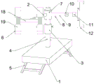
Fig. 1 is a schematic structural diagram of a dual-screen display support frame of the present invention;
fig. 2 is a perspective view of the first support assembly and the second support assembly of the present invention;
fig. 3 is a bottom view of the support plate of the present invention;
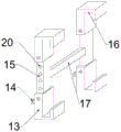
fig. 4 is a schematic structural diagram of the supporting frame of the dual-screen display of this embodiment 2.
In the figure:
1. supporting plate 2, first supporting rod 3 and telescopic shaft
4. Support shaft 5, support leg 6 and first support assembly
7. Rotating sleeve 8, hook 9 and second supporting rod
10. Rotating shaft 11, second rotating shaft 12 and second supporting assembly
13. A second clamping block 14, a second hook 15 and a second telescopic shaft
16. Clamping groove 17, second connecting rod 18 and first connecting rod
19. First block 20, positioning hole
Detailed Description
The present invention will be described in further detail with reference to specific examples. It should be understood that the specific embodiments described herein are for purposes of illustration only and are not intended to limit the scope of the present disclosure, as defined by the following claims.
Example 1
As shown in the figures, the utility model discloses a double screen display ware support frame of electric power customer service field service, including backup pad 1, set up the back shaft 4 on backup pad 1, set up first supporting component 6 and second supporting component 12 on back shaft 4;
the upper part of the supporting shaft 4 is provided with a rotating sleeve 7, and the first supporting component 6 and the second supporting component 12 are connected with the rotating sleeve 7 so as to adjust the positions of the first supporting component 6 and the second supporting component 12 in the horizontal direction;
the first support assembly 6 comprises a first support rod 2, a first connecting rod 18 and 2 first support members, one end of the first support rod 2 is connected with the rotating sleeve 7 of the support shaft 4, the other end of the first support rod is connected with the first connecting rod 18, one end of the first support rod 2 close to the first connecting rod 18 is provided with a rotating shaft 10 for adjusting the angle of the first support member, the first support rod 2 is provided with a first rotating shaft for adjusting the angle in the vertical direction, the 2 first support members are symmetrically arranged at two ends of the first connecting rod 18, each first support member comprises 2 first clamping blocks 19 and a first telescopic shaft arranged between the 2 first clamping blocks 19, each first clamping block 19 is internally provided with a groove for installing the first telescopic shaft, and the 2 first clamping blocks 19 are symmetrically arranged in the vertical direction by taking the first connecting rod 18 as an axis, each first latch 19 is formed with a latch slot 16 for 2 first latches 19 to cooperate with a display.
The second support assembly 12 comprises a second support rod 9, a second connecting rod 17 and 2 second support members, one end of the second support rod 9 is connected with the rotating sleeve 7 of the support shaft 4, the other end of the second support rod is connected with the second connecting rod 17, one end of the second support rod 9 close to the second connecting rod 17 is provided with a rotating shaft 10 for adjusting the angle of the second support member, the second support rod 9 is provided with a second rotating shaft 11 for adjusting the angle of the second support member in the vertical direction, 2 second support members are symmetrically arranged at two ends of the second connecting rod 17, each second support member comprises 2 second fixture blocks 13 and second telescopic shafts 15 arranged between the 2 second fixture blocks 13, a groove is formed in each second fixture block 13 for mounting the second telescopic shafts 15, and the 2 second fixture blocks 13 are symmetrically arranged in the vertical direction by using the second connecting rod 17 as an axis, each second latch 13 is formed with a latch slot 16 for 2 second latches 13 to cooperate with the display.
Furthermore, a first hook 8 and a second hook 148 are respectively and correspondingly arranged on one side of the first latch 19 and one side of the second latch 13 for fixing a connection line of the display.
Furthermore, the first telescopic shaft and the second telescopic shaft 15 are both provided with positioning holes 20 for adjusting the telescopic lengths of the first telescopic shaft and the second telescopic shaft 15.
Further, the edge of the supporting plate 1 is provided with a buckle for fixing with an external desktop.
Further, the bottom of the supporting plate 1 is provided with a foldable supporting leg 5.
Further, a telescopic rod is arranged at the lower part of the supporting shaft 4 for adjusting the telescopic length of the supporting shaft 4.
Example 2
On the basis of embodiment 1, anti-slip pads are arranged on the inner walls of the slots 16 formed on the first latch 19 and the second latch 13.
Further, a hook 8 is arranged below the first support rod 2 and the second support rod 9 for fixing a connection line of the display.
Example 3
As shown in fig. 4, the difference from embodiment 1 is that the supporting plate 1 adopts a supporting platform, and a drawer is provided in the supporting platform for holding articles needed in office work.
Spatially relative terms, such as "upper," "lower," "left," "right," and the like, may be used in the embodiments for ease of description to describe one element or feature's relationship to another element or feature as illustrated in the figures. It will be understood that the spatial terms are intended to encompass different orientations of the device in use or operation in addition to the orientation depicted in the figures. For example, if the device in the figures is turned over, elements described as "below" other elements or features would then be oriented "above" the other elements or features. Thus, the exemplary term "lower" can encompass both an upper and a lower orientation. The device may be otherwise oriented (rotated 90 degrees or at other orientations) and the spatially relative descriptors used herein interpreted accordingly.
Moreover, relational terms such as "first" and "second," and the like, may be used solely to distinguish one element from another element having the same name, without necessarily requiring or implying any actual such relationship or order between such elements.
The invention has been described above by way of example, and it should be noted that any simple variants, modifications or other equivalent substitutions by a person skilled in the art without spending creative effort may fall within the scope of protection of the present invention without departing from the core of the present invention.
Claims (10)
1. The utility model provides a two screen display show ware support frames of electric power customer service field service which characterized in that: the support device comprises a support plate, a support shaft arranged on the support plate, a first support component and a second support component arranged on the support shaft;
the upper part of the supporting shaft is provided with a rotating sleeve, and the first supporting component and the second supporting component are connected with the rotating sleeve so as to be used for adjusting the positions of the first supporting component and the second supporting component in the horizontal direction;
the first support assembly comprises a first support rod, a first connecting rod and 2 first support pieces, one end of the first support rod is connected with the rotating sleeve of the support shaft, the other end of the first support rod is connected with the first connecting rod, a rotating shaft is arranged at one end, close to the first connecting rod, of the first support rod and used for adjusting the angle of the first support piece, a first rotating shaft is arranged on the first support rod and used for adjusting the angle in the vertical direction, the 2 first support pieces are symmetrically arranged at two ends of the first connecting rod, each first support piece comprises 2 first clamping blocks and a first telescopic shaft arranged among the 2 first clamping blocks, a groove is formed in each first clamping block and used for installing the first telescopic shaft, and a clamping groove is formed in each first clamping block and used for clamping the display in a matching mode of the 2 first clamping blocks;
the second supporting component comprises a second supporting rod, a second connecting rod and 2 second supporting pieces, one end of the second supporting rod is connected with the rotating sleeve of the supporting shaft, the other end of the second supporting rod is connected with the second connecting rod, one end, close to the second connecting rod, of the second supporting rod is provided with a rotating shaft for adjusting the angle of the second supporting piece, the second supporting rod is provided with a second rotating shaft for adjusting the angle of the second supporting piece in the vertical direction, the second supporting piece is symmetrically arranged at two ends of the second connecting rod, each second supporting piece comprises 2 second clamping blocks and second telescopic shafts arranged between the 2 second clamping blocks, grooves are formed in each second clamping block for installation, and each second clamping block is provided with a clamping groove for matching with the 2 second clamping blocks to clamp the display.
2. The dual screen display support stand of claim 1, wherein: 2 the first fixture block uses the first connecting rod as an axis and is symmetrically arranged along the vertical direction.
3. The dual screen display support stand of claim 2, wherein: and 2, the second clamping blocks are symmetrically arranged along the vertical direction by taking the second connecting rod as an axis.
4. The dual screen display support stand of claim 3, wherein: and a first hook and a second hook are correspondingly arranged on one side of the first clamping block and one side of the second clamping block respectively and are used for fixing a connecting wire of the display.
5. The dual screen display support stand of claim 4, wherein: and anti-slip pads are arranged on the inner walls of the clamping grooves formed on the first clamping block and the second clamping block.
6. The dual screen display support stand of claim 5, wherein: locating holes are formed in the first telescopic shaft and the second telescopic shaft for adjusting the telescopic lengths of the first telescopic shaft and the second telescopic shaft.
7. The dual screen display support stand of claim 6, wherein: and hooks are arranged below the first supporting rod and the second supporting rod and used for fixing a connecting line of the display.
8. The dual screen display support stand of claim 7, wherein: the edge of the supporting plate is provided with a buckle for fixing with an external desktop.
9. The dual screen display support stand of claim 8, wherein: the bottom of the supporting plate is provided with a foldable supporting leg.
10. The dual screen display support stand of claim 9, wherein: the lower part of the supporting shaft is provided with a telescopic rod for adjusting the telescopic length of the supporting shaft.
Priority Applications (1)
| Application Number | Priority Date | Filing Date | Title |
|---|---|---|---|
| CN201922300373.1U CN211010560U (en) | 2019-12-18 | 2019-12-18 | Double-screen display support frame for electric power customer service field service |
Applications Claiming Priority (1)
| Application Number | Priority Date | Filing Date | Title |
|---|---|---|---|
| CN201922300373.1U CN211010560U (en) | 2019-12-18 | 2019-12-18 | Double-screen display support frame for electric power customer service field service |
Publications (1)
| Publication Number | Publication Date |
|---|---|
| CN211010560U true CN211010560U (en) | 2020-07-14 |
Family
ID=71474261
Family Applications (1)
| Application Number | Title | Priority Date | Filing Date |
|---|---|---|---|
| CN201922300373.1U Active CN211010560U (en) | 2019-12-18 | 2019-12-18 | Double-screen display support frame for electric power customer service field service |
Country Status (1)
| Country | Link |
|---|---|
| CN (1) | CN211010560U (en) |
Cited By (1)
| Publication number | Priority date | Publication date | Assignee | Title |
|---|---|---|---|---|
| CN112600579A (en) * | 2020-12-08 | 2021-04-02 | 深圳市正易电子科技有限公司 | Novel outdoor 4G and 5G wireless data terminal MIFI |
-
2019
- 2019-12-18 CN CN201922300373.1U patent/CN211010560U/en active Active
Cited By (1)
| Publication number | Priority date | Publication date | Assignee | Title |
|---|---|---|---|---|
| CN112600579A (en) * | 2020-12-08 | 2021-04-02 | 深圳市正易电子科技有限公司 | Novel outdoor 4G and 5G wireless data terminal MIFI |
Similar Documents
| Publication | Publication Date | Title |
|---|---|---|
| US9441782B2 (en) | Tablet mounting arm systems and methods | |
| US5362025A (en) | Portable computer support device and means of support | |
| US8605429B2 (en) | All in one computer | |
| WO2005089046A2 (en) | Flat screen display stand | |
| US20080308687A1 (en) | Multi-functional linear utility station | |
| US9250650B2 (en) | Foot support assembly for cantilevered touch screen | |
| CN211010560U (en) | Double-screen display support frame for electric power customer service field service | |
| CN204127590U (en) | Electronic display unit support | |
| US9292043B2 (en) | Flat panel monitor stands | |
| US10791854B2 (en) | Bracket and display device | |
| CN207018789U (en) | Base for display bracket | |
| CN210050545U (en) | Table type round hole fixing display support | |
| CN211096609U (en) | Multifunctional infusion support | |
| CN210954817U (en) | Display screen fixing seat for computer | |
| CN213587708U (en) | Office desk for office building | |
| CN219198632U (en) | Multi-screen display connector | |
| CN213605027U (en) | Teacher of university uses podium | |
| CN214405523U (en) | Supporting component applicable to various occasions and used for electronic product | |
| CN217153712U (en) | Support frame | |
| CN211132919U (en) | Wall pang ball table | |
| CN216590782U (en) | Display support frame of diversified regulation | |
| CN212745612U (en) | Electronic equipment support | |
| CN212657561U (en) | Display screen support | |
| CN216715688U (en) | Multifunctional display support frame | |
| CN216046639U (en) | Portable support |
Legal Events
| Date | Code | Title | Description |
|---|---|---|---|
| GR01 | Patent grant | ||
| GR01 | Patent grant |