CN210780206U - Backup power switching and bus coupling protection measurement and control device - Google Patents
Backup power switching and bus coupling protection measurement and control device Download PDFInfo
- Publication number
- CN210780206U CN210780206U CN201921535678.4U CN201921535678U CN210780206U CN 210780206 U CN210780206 U CN 210780206U CN 201921535678 U CN201921535678 U CN 201921535678U CN 210780206 U CN210780206 U CN 210780206U
- Authority
- CN
- China
- Prior art keywords
- protector
- control device
- protection
- power switching
- control assembly
- Prior art date
- Legal status (The legal status is an assumption and is not a legal conclusion. Google has not performed a legal analysis and makes no representation as to the accuracy of the status listed.)
- Active
Links
Images


Landscapes
- Arrangements For Transmission Of Measured Signals (AREA)
Abstract
The utility model discloses a throw fully and female antithetical couplet protection measurement and control device relates to electrical equipment technical field, for the protection measurement and control device who solves among the prior art operates night or the darker place of light, and the button on the observation device that can't be clear causes the problem that the mistake touched easily. Female antithetical couplet is equipped with one side protector organism of protector, one side of protector organism is provided with the port component board, and the port component board has two, the opposite side of protector organism is provided with outer protection casing, the surface of outer protection casing is provided with outer control assembly, outer control assembly's surface is provided with observes and controls data display screen, observe and control data display screen's below is provided with signal flashing lamp, and signal flashing lamp has a plurality ofly, outer control assembly's below is provided with the upset apron, the surface of upset apron is provided with the protection locked groove, the inboard of upset apron is provided with the combination groove, one side in combination groove is provided with infrared receiver.
Description
Technical Field
The utility model relates to an electrical equipment technical field specifically is a throw fully and female antithetical couplet protection measurement and control device.
Background
The bus coupler is used for connecting buses, and a disconnecting switch and a circuit breaker are generally arranged on the bus coupler, so that the purpose of increasing the power supply reliability is to open the bus coupler at ordinary times. Two sides are generally connected with two different transformers respectively, if one transformer is broken, the other transformer can be used for continuously supplying power to a key load by closing the circuit breaker and the isolating switch, the bus connection is the connection between the buses, and can be a single power supply for double buses. For example, a plurality of workshops are arranged in a factory, each workshop is provided with an independent transformer, if the problem of the transformer in one workshop is solved, the transformer is withdrawn, the other workshop is used for getting electricity to the workshop, the switch closed in the later period is called a bus-tie switch, and different from the dual-power supply, the dual-power supply enters the front end of the transformer in the power supply part and the dual-power supply enters the rear end. The tie switch powered by both sources is called a bridge switch.
However, the existing protection measurement and control device is operated at night or in a place with dark light, so that the keys on the device cannot be clearly observed, and error touch is easily caused; therefore, the existing requirements are not met, and a backup power switching and bus coupler protection measurement and control device is provided for the backup power switching and bus coupler protection measurement and control device.
SUMMERY OF THE UTILITY MODEL
An object of the utility model is to provide a throw fully and female antithetical couplet protection measurement and control device to the protection measurement and control device who proposes in solving above-mentioned background art is operated at night or the darker place of light, and the button on the observation device that can't be clear causes the problem that the mistake touched easily.
In order to achieve the above object, the utility model provides a following technical scheme: a protection measurement and control device for spare power switching and bus coupler comprises a protector body of the spare power switching of the bus coupler, wherein one side of the protector body is provided with two port element plates, the other side of the protector body is provided with an outer protection shell, the outer surface of the outer protection shell is provided with an outer control assembly, the outer surface of the outer control assembly is provided with a measurement and control data display screen, a plurality of signal flashing lamps are arranged below the measurement and control data display screen, a turnover cover plate is arranged below the outer control assembly, the outer surface of the turnover cover plate is provided with a protection locking groove, the inner side of the turnover cover plate is provided with a combination groove, one side of the combination groove is provided with an infrared receiver, the other side of the combination groove is provided with an infrared transmitter, one end of the turnover cover plate is provided with a connection rotating shaft, the top of connecting the pivot is provided with external debugging port, and external debugging port has two, the top of external debugging port is provided with the data control button, and the data control button has a plurality ofly, the top of data control button is provided with response lighting lamp spare.
Preferably, the protector body is connected with the port element plate through a clamping groove, and the protector body is connected with the outer protection shell through a screw.
Preferably, the outer protection shell is fixedly connected with the outer control component, and the induction lighting lamp is connected with the outer control component through a clamping groove.
Preferably, the flip cover is rotatably connected with the outer protective shell through a connecting rotating shaft, the infrared transmitter is FU808L200-BD10, and the infrared receiver is TSOP 31256.
Preferably, the infrared transmitter and the infrared receiver are electrically connected with the induction lighting lamp part, and the external debugging port and the data control key are fixedly connected with the protector body.
Preferably, the bus tie protector comprises a protector wiring circuit.
Compared with the prior art, the beneficial effects of the utility model are that:
1. the utility model discloses an inboard both ends of upset apron are provided with infra-red transmitter and infrared receiver respectively, when the apron is in the closure state, the transmitter and the receiver at both ends will be responded to the separation of illumination lamp spare, so the receiver can't accept the signal from the transmitter, at this moment response illumination lamp spare will be in the outage state, and open the back along the pivot when the apron, infra-red transmitter and infrared receiver also can break away from the separation of light along with the rotation of apron, at this moment the receiver just can receive the signal of transmitter, thereby intercommunication response illumination lamp spare circuit, at this moment response illumination lamp spare will light, throw light on to button operation region.
Drawings
FIG. 1 is an overall front view of the present invention;
FIG. 2 is a diagram of the overall development effect of the present invention;
FIG. 3 is an overall side view of the present invention;
fig. 4 is a wiring circuit diagram of the protector of the present invention.
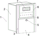
In the figure: 1. a protector is put into the bus tie; 2. a protector body; 3. an outer protective housing; 4. turning over the cover plate; 5. a protection lock slot; 6. an external control assembly; 7. a measurement and control data display screen; 8. a signal flashing light; 9. an infrared receiver; 10. an infrared emitter; 11. a data control key; 12. connecting a debugging port externally; 13. an induction lighting lamp; 14. connecting the rotating shaft; 15. a combination tank; 16. a port plate.
Detailed Description
The technical solutions in the embodiments of the present invention will be described clearly and completely with reference to the accompanying drawings in the embodiments of the present invention, and it is obvious that the described embodiments are only some embodiments of the present invention, not all embodiments.
Referring to fig. 1-4, the present invention provides an embodiment: a protection measurement and control device for backup switching and bus-bar connection comprises a bus-bar connection backup protector 1, a protector body 2 on one side of the bus-bar connection backup protector 1, a port element plate 16 is arranged on one side of the protector body 2, two port element plates 16 are arranged, an outer protection shell 3 is arranged on the other side of the protector body 2 and plays a role in protection, an outer control component 6 is arranged on the outer surface of the outer protection shell 3, a measurement and control data display screen 7 is arranged on the outer surface of the outer control component 6 and is used for displaying measurement and control data in a feedback mode, a signal flashing lamp 8 is arranged below the measurement and control data display screen 7 and is used for displaying the working operation condition of the device, a turnover cover plate 4 is arranged below the outer control component 6, a protection locking groove 5 is arranged on the outer surface of the turnover cover plate 4 and is used for preventing non-workers from operating, a combination groove 15 is arranged on the inner side of the turnover cover plate 4, one side of combination groove 15 is provided with infrared receiver 9, the opposite side of combination groove 15 is provided with the one end of infrared emitter 10 upset apron 4 and is provided with connection pivot 14, the top of connecting pivot 14 is provided with external debugging port 12, and external debugging port 12 has two, the top of external debugging port 12 is provided with data control button 11, and data control button 11 has a plurality ofly, the top of data control button 11 is provided with response light spare 13, can provide lighting service when the operation at night, avoid the staff the condition that the mistake touched to appear and appear.
Further, the protector body 2 is connected with the port element plate 16 through a clamping groove, and the protector body 2 is connected with the outer protection shell 3 through screws, so that stability is enhanced.
Further, outer protection casing 3 and outer control assembly 6 fixed connection, response lighting lamp spare 13 passes through the draw-in groove with outer control assembly 6 and is connected, is convenient for install fixedly.
Further, the flip cover 4 is rotatably connected with the outer protective shell 3 through a connecting rotating shaft 14, the model of the infrared transmitter 10 is FU808L200-BD10, and the model of the infrared receiver 9 is TSOP 31256.
Further, infrared emitter 10 and infrared receiver 9 and response illumination lamp spare 13 electric connection, the cooperation through emitter and receiver comes the opening and closing of control light, external debugging port 12 and data control button 11 and protector organism 2 fixed connection.
Further, the bus tie protector 1 includes a protector wiring circuit, a default breaker jump contact, and a selectable breaker closing contact through a menu control word, and when the device is used to operate a circuit, the signal is not connected, and when the device is not used to operate the circuit, the terminal of the circuit can be disconnected.
The working principle is as follows: when the protector is used, a connector on a port element plate 16 on the back of the device is connected with a corresponding circuit, then the protector body 2 and a corresponding fixing piece are assembled, when the protector body 2 needs to be operated and used, a key is only required to be inserted into a protection locking groove 5 on the outer surface of a turnover cover plate 4, the turnover cover plate 4 is opened through rotation, the bottom of the turnover cover plate 4 is connected with an outer protection shell 3 through a connecting rotating shaft 14 so as to realize the rotary opening and closing of the cover plate, meanwhile, an infrared transmitter 10 and an infrared receiver 9 are respectively arranged at two ends of the inner side of the cover plate, when the cover plate is closed, the receiver cannot receive a signal of the transmitter due to the obstruction of an induction lighting lamp 13, at the moment, the induction lighting lamp 13 is in a power-off state, and after the cover plate is opened, the infrared transmitter 10 and the infrared receiver 9 are separated from the obstruction of a, at this time, the receiver receives the signal from the transmitter to connect the circuit of the induction lighting lamp 13, and the induction lighting lamp 13 is lighted up to illuminate the key operation area.
It is obvious to a person skilled in the art that the invention is not restricted to details of the above-described exemplary embodiments, but that it can be implemented in other specific forms without departing from the spirit or essential characteristics of the invention. The present embodiments are therefore to be considered in all respects as illustrative and not restrictive, the scope of the invention being indicated by the appended claims rather than by the foregoing description, and all changes which come within the meaning and range of equivalency of the claims are therefore intended to be embraced therein. Any reference sign in a claim should not be construed as limiting the claim concerned.
Claims (6)
1. The utility model provides a protection measurement and control device is thrown to spare power supply and mother allies oneself with, includes that the mother allies oneself with and throws protector (1), its characterized in that: the utility model discloses a protector for bus tie is equipped with one side protector organism (2) of protector (1), one side of protector organism (2) is provided with port component board (16), and port component board (16) have two, the opposite side of protector organism (2) is provided with outer protection casing (3), the surface of outer protection casing (3) is provided with outer control assembly (6), the surface of outer control assembly (6) is provided with observes and controls data display screen (7), the below of observing and controlling data display screen (7) is provided with signal flashing lamp (8), and signal flashing lamp (8) have a plurality ofly, the below of outer control assembly (6) is provided with upset apron (4), the surface of upset apron (4) is provided with protection locked groove (5), the inboard of upset apron (4) is provided with combination groove (15), one side of combination groove (15) is provided with infrared receiver (9), the combined type LED lamp is characterized in that an infrared emitter (10) is arranged on the other side of the combined groove (15), a connecting rotating shaft (14) is arranged at one end of the turnover cover plate (4), an external debugging port (12) is arranged above the connecting rotating shaft (14), two external debugging ports (12) are arranged, a data control key (11) is arranged above the external debugging port (12), a plurality of data control keys (11) are arranged, and an induction illuminating lamp piece (13) is arranged above the data control keys (11).
2. The backup power switching and bus coupling protection measurement and control device according to claim 1, wherein: the protector body (2) is connected with the port element plate (16) through a clamping groove, and the protector body (2) is connected with the outer protection shell (3) through a screw.
3. The backup power switching and bus coupling protection measurement and control device according to claim 1, wherein: the outer protection shell (3) is fixedly connected with the outer control assembly (6), and the induction lighting lamp piece (13) is connected with the outer control assembly (6) through a clamping groove.
4. The backup power switching and bus coupling protection measurement and control device according to claim 1, wherein: the turnover cover plate (4) is rotatably connected with the outer protection shell (3) through a connecting rotating shaft (14), the type of the infrared transmitter (10) is FU808L200-BD10, and the type of the infrared receiver (9) is TSOP 31256.
5. The backup power switching and bus coupling protection measurement and control device according to claim 1, wherein: the infrared transmitter (10) and the infrared receiver (9) are electrically connected with the induction lighting lamp piece (13), and the external debugging port (12) and the data control key (11) are fixedly connected with the protector body (2).
6. The backup power switching and bus coupling protection measurement and control device according to claim 1, wherein: the bus tie backup protector (1) comprises a protector wiring circuit.
Priority Applications (1)
| Application Number | Priority Date | Filing Date | Title |
|---|---|---|---|
| CN201921535678.4U CN210780206U (en) | 2019-09-16 | 2019-09-16 | Backup power switching and bus coupling protection measurement and control device |
Applications Claiming Priority (1)
| Application Number | Priority Date | Filing Date | Title |
|---|---|---|---|
| CN201921535678.4U CN210780206U (en) | 2019-09-16 | 2019-09-16 | Backup power switching and bus coupling protection measurement and control device |
Publications (1)
| Publication Number | Publication Date |
|---|---|
| CN210780206U true CN210780206U (en) | 2020-06-16 |
Family
ID=71043343
Family Applications (1)
| Application Number | Title | Priority Date | Filing Date |
|---|---|---|---|
| CN201921535678.4U Active CN210780206U (en) | 2019-09-16 | 2019-09-16 | Backup power switching and bus coupling protection measurement and control device |
Country Status (1)
| Country | Link |
|---|---|
| CN (1) | CN210780206U (en) |
-
2019
- 2019-09-16 CN CN201921535678.4U patent/CN210780206U/en active Active
Similar Documents
| Publication | Publication Date | Title |
|---|---|---|
| WO2021129811A1 (en) | Circuit breaker and power distribution system | |
| CN210780206U (en) | Backup power switching and bus coupling protection measurement and control device | |
| CN203659675U (en) | Modular double-power-supply automatic change-over switch | |
| CN208955743U (en) | A kind of automatic transfer switch controller and its functional module | |
| CN207938569U (en) | A kind of electric cabinet of setting main circuit switch | |
| CN207706129U (en) | Accident indicator for sharing bicycle photovoltaic panel and shared bicycle | |
| CN212433297U (en) | Integrated safety electricity utilization monitoring device | |
| CN205681121U (en) | Formula cut protection device inserted by a kind of wall | |
| CN208299534U (en) | Double power-supply automatic transferring equipment | |
| CN208142054U (en) | A kind of safety device preventing switch on earthing knife-switch by mistake | |
| CN209544183U (en) | A kind of automatic change-over of false-touch prevention | |
| CN207820285U (en) | A kind of novel hotel guest room circuit | |
| CN220285792U (en) | Mining hydraulic support controller with emergency stop lock | |
| CN211655545U (en) | Drawer function locking device | |
| CN215869098U (en) | Isolating switch mechanism | |
| CN219937606U (en) | Intelligent measuring switch | |
| CN208047139U (en) | A kind of fire hydrant control cabinet easy to use | |
| CN214477029U (en) | Switch with full-automatic conversion function | |
| CN211740284U (en) | Intelligent electronic conductive meter | |
| CN209233251U (en) | A kind of novel distribution box of registering one's residence | |
| CN217176261U (en) | Safe electronic panel with external power supply | |
| CN212810868U (en) | Intelligent microcomputer comprehensive protection device | |
| CN214849597U (en) | Distribution box and distribution device | |
| CN214507529U (en) | Intelligent switch | |
| CN220674161U (en) | Push-pull rack-mounted movable ring monitoring host |
Legal Events
| Date | Code | Title | Description |
|---|---|---|---|
| GR01 | Patent grant | ||
| GR01 | Patent grant |