CN210697232U - Milk tea machine - Google Patents
Milk tea machine Download PDFInfo
- Publication number
- CN210697232U CN210697232U CN201921223796.1U CN201921223796U CN210697232U CN 210697232 U CN210697232 U CN 210697232U CN 201921223796 U CN201921223796 U CN 201921223796U CN 210697232 U CN210697232 U CN 210697232U
- Authority
- CN
- China
- Prior art keywords
- liquid
- outer barrel
- spraying
- assembly
- component
- Prior art date
- Legal status (The legal status is an assumption and is not a legal conclusion. Google has not performed a legal analysis and makes no representation as to the accuracy of the status listed.)
- Active
Links
Images


Landscapes
- Apparatus For Making Beverages (AREA)
Abstract
The utility model provides a milk tea machine, which comprises a liquid container, a heating component, an extraction component, a spraying component and a control component, wherein the liquid container is arranged inside the machine body and comprises an outer barrel and an inner barrel nested inside the outer barrel; the heating component is arranged at the lower part of the outer barrel, the spraying component is arranged at the upper part of the outer barrel, and the extraction component is arranged at the lower part of the outer barrel and penetrates through the bottom of the outer barrel to be respectively connected to the spraying component or the inner barrel; the extraction assembly extracts liquid in the outer barrel to the spraying assembly so as to enable the liquid to circulate between the outer barrel and the spraying assembly; or the liquid in the outer barrel is pumped into the inner barrel. The utility model discloses a liquid container has nested bilayer structure, can improve the continuity of tea supply, has improved the homogeneity and the stability of tea temperature, and each part easily dismantles in the container and washs, and the liquid path of parts such as its inside water pump, valve all adopts the silicone tube, is difficult for being blockked up by the tea dirt, is convenient for long-term use and maintenance.
Description
Technical Field
The utility model relates to a preparation facilities of beverage especially relates to a circulating milk tea machine.
Background
Hong Kong milky tea is originated from afternoon tea culture in England, and as early as the middle of the 19 th century, hong Kong people are inexorable with English milky tea. With the continuous exploration and improvement of the formula of the milk tea for many years, Hongkong style milk tea becomes the favorite beverage for Hongkong people, and tea restaurants and ice houses for supplying the milk tea are distributed in the avenue and alleyway of Hongkong. The hong Kong type milk tea is characterized in that the tea brewing mode is named as 'hitting tea', the traditional 'hitting tea' is that tea is placed in a tea bag, tea water is flushed down from a high position to the tea bag by lifting a teapot, the tea bag is circulated and reciprocated for a plurality of times, the tea is brewed in the repeated collision of the tea and the tea water, and more fragrant substances can be absorbed into the tea water. The prepared tea water is put into a heat-preservation container, and when the tea water is drunk, the tea water is fully mixed with seasonings such as milk, sugar and the like, so that the fragrant and delicious Hongkong style milk tea can be obtained.
The process for preparing hong Kong style milky tea by adopting the traditional manual 'hitting tea' mode is more complicated, and a skilled teachers with milky tea can take several minutes to brew a pot of tea water, so that the ever-increasing needs of the catering industry can not be met. In order to solve the defect of slow brewing speed by hand and simultaneously require to furthest reserve the fragrant and thick taste brought by the 'hitting tea' process, the Chinese patent with the publication number of 'CN 108261079A' discloses a spray-type hong Kong milk tea making machine, the milk tea making machine of the invention utilizes a water pump to be matched with a spray pipe to lift hot water from a low position to a high position to carry out spray-type brewing on tea leaves, the tea leaves are automatically refluxed after being made into milk tea, the brewing process is circulated, and the taste of the milk tea is favorably improved. The temperature of the prepared tea water is detected in real time by the temperature monitoring module, and the temperature of the milk tea is kept by the heat preservation sheet.
However, the volume of the inner container of the milk tea machine product adopting the technical scheme is small, after the tea water is used up, the tea water needs to be added manually and then is brewed circularly, the tea water cannot be continuously supplied in the period, and the requirement of the selling peak period cannot be met. Secondly, the tea water after brewing needs to be repeatedly heated by a heat preservation sheet to maintain the temperature, so that the taste of the tea water is influenced. In addition, the inside of the milk tea machine is easy to accumulate tea dirt to cause blockage of pipelines and water paths, is not easy to clean, and is not beneficial to long-term use and maintenance.
SUMMERY OF THE UTILITY MODEL
The utility model provides a milk tea machine, its inside liquid container has nested bilayer structure: tea water is circularly brewed in the outer layer container, the brewed tea water is pumped into the inner layer container to be stored for supply, and then the outer layer container can continuously carry out circular brewing, so that the continuity of tea water supply can be effectively improved. Meanwhile, the tea water stored in the inner container is insulated by the heated liquid in the outer container, so that the uniformity and stability of the temperature of the tea water are ensured. The utility model discloses an each part is easily dismantled and is washd in the container, and the liquid circuit of parts such as its inside water pump, valve all adopts the silicone tube, is difficult for blockking up by the tea dirt, is convenient for long-term use and maintenance.
The utility model adopts the technical scheme as follows:
a milk tea machine comprises a liquid container, a heating component, an extraction component, a spraying component and a control component which are arranged inside a machine body; the liquid container comprises an outer barrel and an inner barrel nested in the outer barrel; the heating component is arranged at the lower part of the outer barrel to heat the liquid in the outer barrel; the spraying component is arranged at the upper part of the outer barrel and is used for brewing the raw materials in a spraying mode; the extraction component is arranged at the lower part of the outer barrel and penetrates through the bottom of the outer barrel to be respectively connected to the spraying component or the inner barrel; the extraction component extracts the liquid in the outer barrel to the spraying component so as to enable the liquid to circulate between the outer barrel and the spraying component; or the liquid in the outer barrel is pumped into the inner barrel.
The utility model discloses a tea milk machine will accomplish in outer bucket that the circulation is steeped tea water of steeping and extract interior bucket and store through the design of above-mentioned double container, can continue to carry out the circulation of next round in the outer bucket and dash and steep, has increased the total supply volume of tea water. Meanwhile, the tea water heated and brewed in the outer barrel is used for heat preservation of the inner barrel, heat loss is small, the temperature is uniform and stable, and the taste of the tea water in the inner barrel can be kept to the maximum extent.
As a specific implementation manner of the utility model, the extraction component comprises an extraction water pipe, a first reversing valve and an extraction water pump; the extraction water pipe penetrates through the bottom of the outer barrel and is connected with the spraying assembly; the first reversing valve can be switched to a liquid path for communicating the outer barrel with the spraying assembly; or, the liquid path is switched to connect the outer barrel and the inner barrel; the extraction water pump extracts liquid from the outer barrel and conveys the liquid to the spraying assembly or the inner barrel.
The utility model discloses an increase by the first switching-over valve of control assembly control, realize very easily from circulating the bubble liquid way to the tea water switching between the liquid way of carrying, not only improved the efficiency of steeping of tea water, still make the structure of product more compact.
As a specific embodiment of the present invention, the control assembly includes a first liquid level sensor and a temperature sensor; the control assembly detects the liquid level in the liquid container and controls the liquid amount pumped by the extraction water pump; the control assembly detects the temperature in the liquid container and adjusts the output power of the heating assembly to control the temperature change in the liquid container, so that the fluctuation of the temperature is limited in a small range, and the temperature shock is prevented.
The utility model discloses utilize temperature sensor to detect the temperature of the inside tea of container, adjust heating element's output through control assembly so that tea keeps at the best temperature of steeping, guarantees the taste of tea. The water level sensor is used for detecting the residual amount of tea water in the container, so that the amount of water for brewing and extracting can be accurately controlled according to actual needs, and the tea water is guaranteed to be supplied uninterruptedly. On the other hand, the heating time can be set according to different water amounts, and the consumption of electric energy can be reduced.
As a specific implementation mode of the utility model, the milk tea machine can also be added with a water inlet component connected with an external water source; the subassembly that intakes includes: the water inlet valve is connected with an external water source and is controlled by the control assembly to adjust the water inflow; the second reversing valve is connected with the water inlet valve and can be switched into a liquid path for communicating the outer barrel with an external water source; or the liquid path is switched to communicate the outer barrel with the extraction assembly.
The utility model discloses an increase the function at the outside water source of lug connection, need not the manual work and add water, effectively improved the preparation efficiency of tea, guaranteed the continuous supply of tea.
As an improvement of the utility model, the control component adjusts the water inflow through the intermittent opening and closing water inlet valve so as to maintain the temperature in the liquid container.
Because the external water source is usually in the room temperature environment and is far lower than the temperature of the tea water in the liquid container, if a large amount of normal temperature water is directly introduced into the outer barrel, the temperature of the tea water stored in the inner barrel can be reduced, and the taste is influenced. Therefore, the utility model discloses an in the improvement, through control water intaking valve intermittent type nature open and close restriction and adjustment inflow, start heating element heating simultaneously and have got into the water in the outer bucket to the temperature in the outer bucket remains throughout at higher temperature, can effectively avoid influencing the tea temperature that is in the heat preservation state in the interior bucket.
As a specific embodiment of the present invention, the spraying assembly includes a spraying device and a filter screen; the spraying device is connected with the extraction component, and the top end of the spraying device is provided with a nozzle for spraying liquid into the filter screen.
In a preferred embodiment, the nozzle is a nozzle disposed on a side wall of the spraying device; the top of the sprinkler is closed. Optionally, the nozzle is more than two nozzles annularly arranged along the side wall of the spraying device.
As an alternative embodiment, the spout top is provided with an umbrella-shaped cover.
The spray assembly for brewing tea leaves requires timely replacement of the tea leaves in the filter screen after completion of a brewing cycle. During the addition of tea leaves to the filter screen, the tea leaf debris easily falls into the nozzle of the sprinkler, causing clogging. The utility model discloses a set up the spout in sprinkler's lateral wall and seal its top, perhaps increase an umbelliform shroud at sprinkler's spout top, can avoid the unexpected jam fault that falls into the spout and lead to of tealeaves piece.
As right the utility model discloses an improvement, the part in the outer bucket, including spray assembly, interior bucket and pass the extraction subassembly of outer bucket bottom and be detachable connection. Meanwhile, a pipeline of a liquid path in the machine body adopts a food-grade silicone tube; the valve in the machine body is a rubber tube extrusion type stop valve, and the opening and the closing are realized by extruding a silicone tube; the water pump in the machine body is a peristaltic pump, and the pumping pressure is provided by forward extruding the silicone tube.
When the milk tea machine is used for a long time, a large amount of tea scale is usually accumulated on the inner wall of a pipeline, the sealing position of a valve, the surface of a water pump impeller and the joint of each part inside the milk tea machine, so that bacteria are easy to breed, and the pipeline is possibly blocked to cause equipment failure and lower the preparation efficiency of tea. The utility model discloses the washing all can be dismantled to the part in the outer bucket, has improved the inside clean efficiency of container, has reduced the routine maintenance and the clear degree of difficulty. In addition, the internal liquid path adopts a silica gel pipeline, so that the number of joints is reduced as much as possible; meanwhile, a valve used by the milk tea machine in the prior art is further replaced by a rubber tube extrusion type stop valve, and a water pump is replaced by a peristaltic pump, so that the problem of tea scale accumulation at positions such as a valve sealing position and the surface of a water pump impeller is solved, and the pipeline can be automatically cleaned in the process of repeatedly extruding a silicone tube.
To sum up, the utility model discloses an milk tea machine has solved among the prior art the container capacity problem less than normal, that the heat preservation effect is relatively poor through the design of double-deck container. And the preparation efficiency of the tea water is further improved by adding a water supply device of an external water source. Simultaneously, through redesigning the spraying device, the blockage of the spray head is avoided. The silica gel pipeline, water valve and the water pump of integration can effectively avoid the tea dirt deposit, and the detachable design of container internals has also promoted abluent facility, makes the utility model discloses the product has higher maintainability.
It should be noted that the technical solution of the present invention is not limited to the preparation of tea, but is also applicable to the preparation of other similar or similar beverages, such as coffee. The description of the present invention in relation to the preparation of tea should not be construed as limiting the scope of the invention.
Drawings
Fig. 1 is a schematic view of an overall structure of a milk tea machine provided by an embodiment of the present invention;
FIG. 2 is a schematic view of the working state of step 1 in the embodiment of the present invention;
FIG. 3 is a schematic diagram of the working state of step 2 in the embodiment of the present invention;
FIG. 4 is a schematic diagram of the working state of step 3 in the embodiment of the present invention;
FIG. 5 is a schematic diagram of the working state of step 4 in the embodiment of the present invention;
FIG. 6 is a schematic diagram of the working status of step 5 in the embodiment of the present invention;
fig. 7 is a schematic structural view of the interior of the container and the spray assembly in an embodiment of the present invention;
fig. 8 is a schematic structural diagram of a spout portion of a spray assembly according to an embodiment of the present invention.
Detailed Description
In order to make the technical solution of the present invention better understood, the technical solution of the embodiments of the present invention will be clearly and completely described below with reference to the accompanying drawings in the embodiments of the present invention, and it is obvious that the described embodiments are only some embodiments of the present invention, not all embodiments. Based on the embodiments in the present invention, all other embodiments obtained by a person skilled in the art without creative efforts shall belong to the protection scope of the present invention.
The terms "first," "second," "third," and the like in the description and in the claims, and in the drawings described above, are used for distinguishing between different objects and not necessarily for describing a particular order. Furthermore, the terms "include" and "have," as well as any variations thereof, are intended to cover non-exclusive inclusions.
The present invention will be described in more detail with reference to the embodiments shown in the drawings.
Referring to fig. 1, an embodiment of the present invention provides a milk tea machine, an inner container of the milk tea machine is a nested double-layer structure, tea water is brewed in an outer container in a circulating manner, the brewed tea water is pumped into an inner container for storage, and the tea water in the outer container is used for heat preservation.
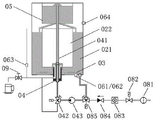
As shown in fig. 1, the milk tea machine of the present invention mainly comprises a machine body 01, a liquid container 02, a heating component 03, an extraction component 04, a spraying component 05 and a control component 06. Specifically, the liquid container 02 includes an outer barrel 021 and an inner barrel 022, and the inner barrel 022 is nested inside the outer barrel 021.
The extracting component 04 is disposed at the lower part of the outer barrel 021, and an extracting water pipe 041 of the extracting component 04 penetrates through the bottom of the outer barrel 021 to be connected with the spraying component 05, and is used for extracting the liquid in the outer barrel 021 to the spraying component 05, so that the liquid circulates between the outer barrel 021 and the spraying component 05.
The heating element 03 is disposed at a lower portion of the outer tub 021, and mainly functions to heat a first liquid, such as drinking water, in the outer tub 021. The heating component 03 can be disposed outside the outer tub 021, or integrated with the bottom of the outer tub 021, or disposed inside the outer tub 021, and can be a heating plate, a heating tube, or other devices capable of achieving similar functions. The heating component 03 is controlled by the control component 06 and is used for heating the first liquid in the outer barrel 021 to a proper brewing temperature. For example, the brewing temperature may be set to 95 ℃ when brewing tea leaves.
The spraying component 05 is arranged on the upper part of the outer barrel 021 and comprises a spraying device 051 and a filter screen 052, and raw materials, such as tea leaves, can be placed in the filter screen 052. The spraying device 051 sprays the heated first liquid to the filter screen 052, and the brewing of the raw materials is completed in a spraying mode. The second liquid formed after brewing flows out of the sieve holes at the bottom of the filter screen 052 and returns to the outer barrel 021. According to the brewing requirements of different raw materials, the extraction component 04 needs to circularly extract the liquid from the outer barrel 021 to the spray component 05 for multiple times so as to enable the second liquid to achieve the optimal taste.
After the circulation brewing process is completed, the extraction assembly 04 completely extracts the second liquid in the outer barrel 021 into the inner barrel 022 for storage. The lid 07 can then be opened to change the feedstock in the spray assembly 05 and the first liquid can be added to the outer barrel 021. Thereafter, the control component 06 controls the heating component 03 again to heat the first liquid in the outer tub 021 for maintaining the temperature of the second liquid in the inner tub 022.
In order to rapidly switch the liquid in the outer barrel 021 from the liquid conveyed to the spraying assembly 05 to the liquid conveyed to the inner barrel 022, the extraction assembly 04 adopts a reversing valve to realize the switching of a liquid passage (hereinafter referred to as a liquid passage).
Referring to fig. 2, the extraction assembly 04 includes an extraction water pipe 041, a first directional valve 042 and an extraction water pump 043, and the extraction water pipe 041 passes through the bottom of the outer tub 021 and is connected to the spray assembly 05. The first reversing valve 042 is controlled by the control component and can be switched to a liquid path for communicating the outer barrel 021 with the spraying component 05; or, the liquid path is switched to connect the outer barrel 021 and the inner barrel 022.
When the first reversing valve 042 is switched to a liquid path for communicating the outer barrel 021 with the spraying assembly 05, the extraction water pump 043 extracts liquid from the outer barrel 021 and conveys the liquid to the spraying assembly 05; when the first direction valve 042 is switched to the liquid path for communicating the outer barrel 021 and the inner barrel 022, the extraction water pump 043 extracts the liquid from the outer barrel 021 and transmits the liquid to the inner barrel 022.
In particular, referring to fig. 2, the control assembly includes a first level sensor 061 and a temperature sensor 062. Wherein, the first liquid level sensor 061 is used for detecting the liquid level in the outer barrel 021, the second liquid level sensor 063 is used for detecting the liquid level in the inner barrel 022, and the temperature sensor 062 is used for detecting the temperature in the outer barrel 021. The third level 064 sensor is a safety protection device for preventing the liquid level in the outer tub 021 from exceeding the maximum for normal operation.
According to the needs of the user, the control component can control the amount of liquid pumped by the extraction water pump 043 according to the detection result of the first liquid level sensor 061. For example, in the circulating brewing process, the total extracted liquid amount is determined according to the liquid amount of the first liquid in the outer barrel 021 so as to meet the brewing time requirement. Alternatively, the remaining liquid amount in the outer barrel 021 is detected at any time while the second liquid is being transferred to the inner barrel 022. The control component can also set the heating time of the heating component 03 according to the liquid allowance in the outer barrel 021, and the consumption of electric energy can be reduced.
On the other hand, the control module detects the temperature in the liquid container through the temperature sensor 062 to adjust the output power of the heat generating module 03 to control the temperature in the liquid container. The temperature change range is controlled in an interval as small as possible near the optimal temperature value, so that the temperature shock is prevented, and the taste of the tea water in the circulating brewing process is ensured.
With continuing reference to fig. 2, the milk tea machine of the present invention has a water inlet assembly connected to an external drinking water source. The water inlet assembly comprises a water inlet filter 081, a water inlet valve 082, a flowmeter 083, a check valve 084, a second reversing valve 085 and the like.
Wherein the inlet filter 081 is directly connected to an external water source. The water inlet valve 082 is connected with the control component, and the water inlet quantity is adjusted by controlling the opening and closing time of the water inlet valve 082, so that the heat preservation temperature of the tea water in the inner barrel is prevented from being influenced by the sudden drop of the water temperature in the container caused by the too fast water inlet. A check valve 084 for preventing backflow of liquid in the container and a flow meter 083 for detecting the flow rate of the inflow water are optionally installed between the inflow valve 082 and the second direction changing valve 085. The second reversing valve 085 is controlled by the control component and can be switched to a liquid path for communicating the outer barrel 021 with an external water source; or, the liquid path is switched to connect the outer barrel 021 and the extraction assembly 04.
Referring to fig. 7, the spraying component 05 of the milk tea machine of the present invention is composed of a spraying device 051 and a filter screen 052. The spraying device 051 is connected with an extraction water pipe 041, and the first liquid extracted from the outer barrel 021 is sent to the spraying device 051 through the extraction water pipe 041 and is sprayed to the raw material placed in the filter screen 052 through a nozzle 053 at the top end of the spraying device. The first liquid and the raw materials are mixed and brewed to form a second liquid, and the second liquid flows downwards through the sieve holes at the bottom of the filter screen 052 and flows back into the outer barrel 021 to form circular brewing.
A water dropping plate 054 is arranged below the nozzle 053 to ensure that the first liquid is fully contacted with the raw material. The dripping plate 054 is uniformly perforated to allow the first liquid to drip onto the surface of the raw material from different locations, so that the brewing is more complete.
When the materials in the filter screen 052 are fully brewed, the spraying assembly 05 needs to be taken down for replacing the materials. Since the raw material is generally made into fine powder particles and easily drops into the spout 053 during the addition and replacement of the raw material to cause clogging, it is possible to prevent the raw material particles from accidentally entering the spout 053 by adding an umbrella-shaped cover over the spout 053.
The spraying component 05, the inner barrel 022 and the extraction component (such as the extraction water pipe 041) penetrating through the bottom of the outer barrel are detachably connected, and can be sequentially detached to be cleaned when being cleaned, so that the daily maintenance is facilitated.
Referring to fig. 8, as an alternative, the top of the spraying device 051 is closed, and the nozzles 053 are disposed on the side wall of the spraying device 051 to form nozzles having a certain angle with the vertical downward direction. The spray orifices 053 may consist of two or more nozzles arranged annularly along the side wall of the spraying device 051. By adopting the scheme, raw material particles can be prevented from entering without adding an umbrella-shaped cover above the nozzle 053, and the structure is more compact.
The utility model discloses in, the valve of first switching-over valve adopts rubber tube extrusion formula stop valve, realizes the switching of liquid route through the extrusion silicone tube. Therefore, for traditional valve, the utility model discloses an among the rubber tube extrusion formula stop valve, the silicone tube through the valve forms integratively with the connecting tube at both ends, need not to increase the attach fitting, has not only simplified the structure, can prevent moreover that valve, joint department from accumulating the tea dirt. The rubber tube extrusion type stop valve is also suitable for other valves such as a second reversing valve, a water inlet valve and the like.
The utility model discloses in, the extraction water pump adopts the peristaltic hose pump, provides the pump pressure through the liquid in the extrusion silicone tube forward. For traditional impeller pump or piston pump, the utility model discloses an among the hose peristaltic pump, the silicone tube through the pump body forms integratively with the connecting tube at both ends, need not to increase attach fitting, has not only simplified the structure, can prevent moreover that the pump body, joint department from accumulating the tea dirt.
For further understanding the utility model discloses, introduce the utility model discloses a milk tea machine's theory of operation below:
before the milk tea machine is used, the water inlet assembly is connected to an external drinking water source, and raw materials are placed in the filter screen. After the power is switched on, a user can select the preparation amount of the tea water according to actual needs, and the milk tea machine automatically enters a brewing procedure for preparing the tea water.
Step 1: referring to fig. 2, after entering the brewing process, the control component switches the second direction valve 085 to a liquid path connecting the outer tub 021 and the water inlet valve 082, and after opening the water inlet valve 082, the first liquid from the external water source sequentially passes through the filter 081, the water inlet valve 082, the flow meter 083, the check valve 084 and the second direction valve 085 and enters the inside of the outer tub 021. When the first liquid entering the outer tub 021 reaches a preset capacity, the first liquid level sensor 061 informs the control assembly to close the water inlet valve 082.
Step 2: referring to fig. 3, the outer tub 021 is filled with the first liquid, the control assembly activates the heating assembly to heat the first liquid, and the temperature sensor 062 monitors the temperature in the outer tub in real time. When the first liquid in the outer barrel 021 reaches the preset brewing temperature, the control assembly switches the second reversing valve 085 to a liquid path communicating the outer barrel 021 with the extraction assembly 04, and simultaneously switches the first reversing valve 042 to a liquid path communicating the outer barrel 021 with the spraying assembly 05. The extraction pump 043 is activated to extract the first liquid from the outer barrel 021 to the spray assembly 05. The first liquid is fully mixed with the raw materials in the spraying component 05 to complete the brewing to form a second liquid, and the second liquid flows back to the outer barrel 021 through a filter screen below the spraying component 05 to form a brewing cycle. The duration of the brewing cycle is determined by the control unit according to the preset amount of tea water to be prepared.
And step 3: referring to fig. 4, after the brewing cycle is completed, the outer barrel 021 is filled with the second liquid, and the control assembly switches the first direction valve 042 to a liquid path connecting the outer barrel 021 and the inner barrel 022. The extraction pump 043 is started to extract the second liquid from the outer barrel 021 into the inner barrel 022. When the first liquid level sensor 061 detects that the outer tub 021 is empty, the control assembly stops drawing liquid.
And 4, step 4: referring to fig. 5, after the brewing process is completed, the tea water prepared in the inner barrel 022 is automatically kept warm by the warm keeping process. At this time, the outlet valve 09 may be opened to pour out the prepared tea water from the inner barrel 022. In the heat preservation procedure, the control component switches the second reversing valve 085 to a liquid path communicating the outer barrel 021 and the water inlet valve 082, opens the water inlet valve 082 to inject the first liquid into the outer barrel and starts the heating component 03, and the heated first liquid in the outer barrel 021 is used as the second liquid in the inner barrel 022 for heat preservation. The mode similar to the water bath heat preservation mode not only has uniform temperature distribution and small heat loss, but also can not generate tea scale deposition in the outer barrel 021 even if the first liquid is repeatedly heated.
In order to prevent the temperature in the liquid container 02 from being lowered by injecting the first liquid at normal temperature in large quantities at a time, the water supply in the heat-keeping process is performed intermittently. The control component controls the water inlet valve 082 to be intermittently closed, so that only a small amount of first liquid in a room temperature state is injected into the outer barrel 021 each time, and after the heating component 03 heats the first liquid injected previously to a temperature required by heat preservation, the water inlet valve 082 is opened to continuously inject a small amount of first liquid. Through the circulation of the water injection and the heating, the temperature shock in the outer barrel can be prevented from influencing the heat preservation temperature of the tea water in the inner barrel.
And 5: referring to fig. 6, in a time period when a large amount of tea water is required, the heat-preserving process in step 5 may be interrupted at any time to start the circulating brewing process in the outer tub 021, i.e., the steps 1 to 3 are repeated to fill the outer tub 021 and the inner tub 022 with the prepared tea water. When the second liquid level sensor 063 detects that the tea water in the inner barrel 022 is insufficient, the tea water can be extracted from the outer barrel 021 at any time, and the condition of tea water supply interruption is prevented.
The utility model realizes the continuous supply of tea water through the circulation of the brewing program and the heat preservation program; in the whole operation process, the user only needs to add or replace the raw materials according to the requirements, so that the manual intervention is reduced, and the preparation efficiency of the tea water is improved.
In the above embodiments, the descriptions of the respective embodiments have respective emphasis, and for parts that are not described in detail in a certain embodiment, reference may be made to the related descriptions of other embodiments.
The above description is only a preferred embodiment of the present invention and is not intended to limit the present invention, and various modifications and changes may be made by those skilled in the art. Any modification, equivalent replacement, or improvement made within the spirit and principle of the present invention should be included in the protection scope of the present invention.
Claims (10)
1. The utility model provides a milk tea machine, is including setting up in inside liquid container, the heating element of organism, extracting subassembly, spray assembly and control assembly, its characterized in that: the liquid container comprises an outer barrel and an inner barrel nested in the outer barrel; the heating component is arranged at the lower part of the outer barrel so as to heat liquid in the outer barrel; the spraying assembly is arranged at the upper part of the outer barrel and is used for brewing the raw materials in a spraying mode; the extraction component is arranged at the lower part of the outer barrel and penetrates through the bottom of the outer barrel to be connected to the spraying component or the inner barrel respectively; the extraction assembly extracts liquid in the outer barrel to the spraying assembly so as to enable the liquid to circulate between the outer barrel and the spraying assembly; or the liquid in the outer barrel is pumped into the inner barrel.
2. The milk tea machine according to claim 1, characterized in that: the extraction assembly comprises an extraction water pipe, a first reversing valve and an extraction water pump; the extraction water pipe penetrates through the bottom of the outer barrel and is connected with the spraying assembly; the first reversing valve can be switched to be a liquid path for communicating the outer barrel with the spraying assembly; or, the liquid path is switched to communicate the outer barrel and the inner barrel; the extraction water pump extracts liquid from the outer barrel and conveys the liquid to the spraying assembly or the inner barrel.
3. The milk tea machine according to claim 2, characterized in that: the control assembly comprises a first liquid level sensor and a temperature sensor; the control assembly detects the liquid level in the liquid container and controls the amount of liquid pumped by the extraction water pump; the control assembly detects the temperature in the liquid container and adjusts the output power of the heating assembly to control the temperature change in the liquid container.
4. The milk tea machine according to claim 1, characterized in that: the water inlet component is also included; the water inlet assembly comprises: the water inlet valve is connected with an external water source and is controlled by the control component to adjust the water inlet quantity; a second reversing valve connected with the water inlet valve and capable of being switched into a liquid path for communicating the outer barrel with an external water source; or the liquid path is switched to communicate the outer barrel with the extraction assembly.
5. The milky tea machine of claim 4, wherein: the control component adjusts the water inflow by intermittently opening and closing the water inlet valve so as to maintain the temperature in the liquid container.
6. The milk tea machine according to claim 1, characterized in that: the spraying assembly comprises a spraying device and a filter screen; the spraying device is connected with the extraction assembly, and the top end of the spraying device is provided with a nozzle for spraying liquid into the filter screen.
7. The milk tea machine according to claim 6, characterized in that: the nozzle is a nozzle arranged on the side wall of the spraying device; the top of the spraying device is closed.
8. The milky tea machine of claim 7, wherein: the nozzle is more than two nozzles annularly arranged along the side wall of the spraying device.
9. The milk tea machine according to claim 6, characterized in that: the top of the spout is provided with an umbrella-shaped cover.
10. The milk tea machine according to any one of claims 1 to 9, characterized in that: the components in the outer barrel comprise a spraying component, an inner barrel and an extraction component penetrating through the bottom of the outer barrel, which are detachably connected.
Priority Applications (1)
| Application Number | Priority Date | Filing Date | Title |
|---|---|---|---|
| CN201921223796.1U CN210697232U (en) | 2019-07-31 | 2019-07-31 | Milk tea machine |
Applications Claiming Priority (1)
| Application Number | Priority Date | Filing Date | Title |
|---|---|---|---|
| CN201921223796.1U CN210697232U (en) | 2019-07-31 | 2019-07-31 | Milk tea machine |
Publications (1)
| Publication Number | Publication Date |
|---|---|
| CN210697232U true CN210697232U (en) | 2020-06-09 |
Family
ID=70956459
Family Applications (1)
| Application Number | Title | Priority Date | Filing Date |
|---|---|---|---|
| CN201921223796.1U Active CN210697232U (en) | 2019-07-31 | 2019-07-31 | Milk tea machine |
Country Status (1)
| Country | Link |
|---|---|
| CN (1) | CN210697232U (en) |
Cited By (1)
| Publication number | Priority date | Publication date | Assignee | Title |
|---|---|---|---|---|
| CN111773960A (en) * | 2020-07-23 | 2020-10-16 | 湖南文理学院 | Highland barley milk tea processing is with agitating unit who has filtration |
-
2019
- 2019-07-31 CN CN201921223796.1U patent/CN210697232U/en active Active
Cited By (2)
| Publication number | Priority date | Publication date | Assignee | Title |
|---|---|---|---|---|
| CN111773960A (en) * | 2020-07-23 | 2020-10-16 | 湖南文理学院 | Highland barley milk tea processing is with agitating unit who has filtration |
| CN111773960B (en) * | 2020-07-23 | 2022-01-28 | 湖南文理学院 | Highland barley milk tea processing is with agitating unit who has filtration |
Similar Documents
| Publication | Publication Date | Title |
|---|---|---|
| JP6564760B2 (en) | Automatic coffee drip equipment | |
| US7654191B2 (en) | Beverage dispenser | |
| US5303639A (en) | Automatic brewer | |
| CN102648149B (en) | Systems for on demand iced tea | |
| CA2133531C (en) | Automatic brewer | |
| CA2292813C (en) | Tea brewing apparatus | |
| CN102238889A (en) | Electric infusion beverage makers | |
| CN101301166A (en) | Full-automatic table for making tea | |
| US20210219766A1 (en) | Infusion beverage apparatus | |
| CN103079437A (en) | Beverage brewing apparatus and method | |
| US10980369B2 (en) | Infusion beverage apparatus | |
| CN210697232U (en) | Milk tea machine | |
| CN201029774Y (en) | Liquid automatically providing kettle | |
| US20210386225A1 (en) | Beverage brewing pot and beverage brewing method using same | |
| CN105125083B (en) | One kind makes bean coffee machine | |
| CN111669998B (en) | Machine and method for preparing beverages | |
| CN111972593A (en) | Blood sugar reducing rice cooking method | |
| CN111655090B (en) | Machine for preparing beverages and control method | |
| CN214804157U (en) | Disconnect-type heating brewing device | |
| CN201227172Y (en) | Full automatic tea stewing desk | |
| CN208941814U (en) | A kind of novel coffee machine | |
| JP2006198213A (en) | Apparatus for preparing coffee beverage | |
| CN209252476U (en) | A kind of coffee machine | |
| CN102578916A (en) | Mixing device applicable to brewing Turkish coffee | |
| CN209595395U (en) | A kind of automatic water filling type ceramic utensil |
Legal Events
| Date | Code | Title | Description |
|---|---|---|---|
| GR01 | Patent grant | ||
| GR01 | Patent grant |