CN203163564U - Loop gravity assisted heat pipe heat transfer device provided with flat plate type evaporator - Google Patents
Loop gravity assisted heat pipe heat transfer device provided with flat plate type evaporator Download PDFInfo
- Publication number
- CN203163564U CN203163564U CN2012206897002U CN201220689700U CN203163564U CN 203163564 U CN203163564 U CN 203163564U CN 2012206897002 U CN2012206897002 U CN 2012206897002U CN 201220689700 U CN201220689700 U CN 201220689700U CN 203163564 U CN203163564 U CN 203163564U
- Authority
- CN
- China
- Prior art keywords
- plate evaporator
- condenser
- gravity assisted
- heat pipe
- heat transfer
- Prior art date
- Legal status (The legal status is an assumption and is not a legal conclusion. Google has not performed a legal analysis and makes no representation as to the accuracy of the status listed.)
- Expired - Fee Related
Links
Images


Landscapes
- Cooling Or The Like Of Semiconductors Or Solid State Devices (AREA)
Abstract
The utility model discloses a loop gravity assisted heat pipe heat transfer device provided with a flat plate type evaporator. The device adopts a vacuum seal structure and mainly comprises the flat plate type evaporator, a condenser, a steam pipeline and a liquid pipeline, wherein the flat plate type evaporator, the condenser, the steam pipeline and the liquid pipeline form a loop gravity assisted heat pipe, and the loop gravity assisted heat pipe is filled with a working medium. According to the loop gravity assisted heat pipe heat transfer device, efficient heat transfer can be realized, and the overall system heat efficiency is improved; and at the same time, the device is simple in modeling structure, convenient to install, low in construction cost and high in space utilization rate. An application range of the loop gravity assisted heat pipe is enlarged due to the introduction of the flat plate type evaporator; and the efficient and cheap heat transfer device is provided for the utilization of terrestrial heat and solar energy, can also be a reliable heat radiation choice for a plane heat source such as a CPU, an LED chip and the like, and is suitable for heat transfer and heat radiation of the flat plate type heat source with a high heat flow density in a gravity environment.
Description
Technical field
The utility model belongs to field of energy utilization, and the heat radiation, the heat that can be applicable to electronic device or main equipment efficiently conduct, and is specifically related to a kind of loop gravity assisted heat pipe heat transfer unit (HTU) with plate evaporator.
Background technology
For the third time after the industrial revolution, especially entered since 21 century, along with improving constantly of scientific and technological level, semiconductor electronic industry flourish, progressing greatly day by day of integrated technology, the progress of advancing by leaps and bounds is constantly explored and obtained to electronic electric equipment to the direction of high-performance high power small size, but can produce heat in the electronic equipment components and parts course of work, power is more high, the heat of Chan Shenging is also just more big thereupon, if heat can't distribute, just can make components and parts operating efficiency under the overtemperature state reduce, even burn.Therefore in recent years, along with the integrated degree of high performance high performance components is more and more higher, the heat dissipation problem of electronic and electrical equipment is also more and more outstanding.The heat flow density of electronic devices and components unit are increases and increases along with the power of unit are, for heat flow density greater than 10W/cm
2Situation, traditional take section bar to squeeze the type radiator to be difficult to the radiating effect that reaches desirable in conjunction with the mode of fan forced convection heat radiation, and take Water Cooling Technology, especially the active water-cooling technology of power set of self need arranging in pairs or groups is easy to generate reliability and the life problems of power part and seal, so prior art adopts the technological means of phase-change heat transfer usually, solve heat flow density 10W/cm
2---100W/cm
2Heat dissipation problem, nowadays, general heat pipe has been applied in electric industry more at large, however the heat transfer limitation of himself makes its heat-sinking capability be confined to 30W/cm
2About.
In addition, the gravity assisted heat pipe device has become the heat transfer unit (HTU) of comparative maturity now, is widely used in geothermal energy utilization and solar energy heat utilization field.The gravity assisted heat pipe device is to utilize gravity as driving force, allows be in the heat transfer unit (HTU) that working medium in the negative pressure closed environment undergoes phase transition the conduction heat, because it is simple in structure and have very high heat transfer coefficient, so heat transfer efficiency is higher.In recent years, in the separated type solar water heater, had to use the gravity assisted heat pipe device as the design of heat transfer component and use and occurred.In recent years, the separated type solar water heater becomes the hot research problem of solar water heater project in recent years because the separate design of its heat collector and storage tank has enlarged the fitting limit of solar water heater.Yet the separated type solar water heater often adopts repeatedly indirect heat exchange that the water in the water tank is heated, make system's efficiency of heating surface low than the close-coupled solar water heater, and be subjected to the traditional gravity Heat Transfer of Heat Pipe on Heat Pipe limit especially entrainment limit limit realization solar thermal collector and the remote apart arrangement of storage tank that the existing separated type solar water heater that utilizes the traditional gravity heat pipe can not be real.Use the separated type solar water heater of traditional gravity heat pipe and compare traditional some, use loop gravity assisted heat pipe device can further reduce heat transfer resistance, strengthen system's heat exchange efficiency, and realize remotely transferring.And its easy-to-install characteristics also make the traditional traditional gravity heat pipe of replacement become possibility.
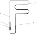
Existing loop gravity assisted heat pipe generally as shown in Figure 7, the loop gravity assisted heat pipe mainly comprises and has evaporimeter 10, condenser 20, up steam pipework 30 and the descending liquid pipeline 40 that evaporates conduit 11, wherein condenser 20 is arranged in evaporimeter 10 tops, the two ends of up steam pipework 30 are connected with the top of evaporimeter 20, and the two ends of descending liquid pipeline 40 link to each other with the below of evaporimeter 10, condenser 20 respectively.Such loop gravity assisted heat pipe can augmentation of heat transfer, reduce thermal resistance, improve efficiency of utilization, but existing loop gravity assisted heat pipe main some problems that exist also in actual applications:
1, this loop gravity assisted heat pipe structure evaporator section upper and lower side respectively needs to insert at least one pipeline, this uses at the existing gravity assisted heat pipe of existing replacement and has inconvenience and defective, reason is that present gravity assisted heat pipe application is generally the closed type structure that has only upper space to leave the sealing of pipe outlet lower space, and the project organization that must change existing application can be replaced the traditional gravity heat pipe with existing loop gravity assisted heat pipe;
Though 2, existing loop gravity assisted heat pipe is simple in structure, cost is not high, has higher difficulty of construction, and maintenance cost is higher, is unsuitable for extensive popularization;
3, the tubular evaparator loop gravity assisted heat pipe device that proposes before has certain application limitation, for example can not be used as the heat radiation of flat thermals source such as CPU, led chip well.
The utility model content
In order to overcome the deficiency that there are problems in existing loop gravity assisted heat pipe heat transfer unit (HTU), the purpose of this utility model is: a kind of loop gravity assisted heat pipe heat transfer unit (HTU) with plate evaporator is provided, this device relies on gravity as driving force, need not outer power source, can realize efficient heat transmission, improve the total system thermal efficiency, the modeling structure of device own is simple simultaneously, easy for installation, cost is low, space availability ratio is high.The introducing of device middle plateform formula evaporimeter has enlarged the range of application of loop gravity assisted heat pipe, is providing for geothermal utilization and solar energy utilization beyond efficient, the cheap heat transfer apparatus, also can become the selection of dispelling the heat reliably of plane thermals source such as CPU, led chip.
The technical scheme that its technical problem that solves the utility model adopts is as follows:
A kind of loop gravity assisted heat pipe heat transfer unit (HTU) with plate evaporator, described loop gravity assisted heat pipe heat transfer unit (HTU) is vacuum seal structure, it mainly comprises plate evaporator, condenser, steam pipework and liquid line; Described plate evaporator is provided with at least one, this plate evaporator is located at the below of described whole loop gravity assisted heat pipe heat transfer unit (HTU), described condenser is provided with at least one, this condenser is located at the top of plate evaporator, the arrival end of described steam pipework stretches into the top of plate evaporator and is positioned at the top of this plate evaporator, and the port of export of described liquid line passes the top of plate evaporator and is inserted into the bottom of this plate evaporator; The port of export of described steam pipework is communicated with the top of described condenser, and the arrival end of described liquid line is communicated with the bottom of condenser, constitutes loop; Form the loop gravity assisted heat pipe by described plate evaporator, condenser, vapor line and liquid line, charged working medium in this loop gravity assisted heat pipe inside.
Described plate evaporator be shaped as the rectangle bodily form, the cylinder bodily form, the hemisphere bodily form with planar structure; One-sided or many sides of described plate evaporator have the heating plane that is complementary with plate evaporator thermal source heating face.
The inner surface of described plate evaporator is smooth surface, but or the grooved surface of augmentation of heat transfer performance, array pin finned surface, inner sintered porous material layer.
Described condenser internal face is shiny surface, but or the straight flute of enforcing condensation heat exchange property, spiral grooves wall or adhere to heat exchange surface coating wall; The outside wall surface of described condenser is smooth surface, or is provided with fin or rib structure in outside wall surface, or on outside wall surface the peripheral hardware water-cooling structure.
At described steam pipework or liquid line three-port structure is set, this three-port structure is provided with bleeding point also can be airtight.
The material of described plate evaporator and condenser is copper or aluminium or the stainless steel with excellent heat conductivity performance; The material of described steam pipework and liquid line and three-port structure is copper or aluminium or stainless steel or the polytetrafluoroethylene (PTFE) that does not react with working medium.
Described working medium has the liquid working substance of good thermophysical property for what can undergo phase transition in the operating temperature district.
Know-why of the present utility model is as follows: the plate evaporator in the utility model is the position as loop gravity assisted heat pipe device and thermal source generation exchange heat, thermal source conducts heat to plate evaporator by heat conduction, thermal convection current or thermal-radiating mode, after plate evaporator absorbs enough heats, the vaporization phase transformation takes place in the liquid working substance of internal reservoir, realizes the heat exchange between thermal source and the working medium.Condenser of the present utility model is the position as loop gravity assisted heat pipe device and low-temperature receiver (heat sink) generation exchange heat, condenser is discharged into low-temperature receiver with the heat that absorbs, the phase transformation of condensing because heat runs off of steam inside working medium, the heat exchange between realization working medium and the low-temperature receiver.Steam pipework or liquid line set in the utility model are that working medium forms the used passage of loop, and are provided with the closed three-port structure of bleeding point.The matching design of the utility model dependence plate evaporator and steam pipework, liquid line makes gas phase and liquid phase working fluid only pass in and out and the lower end complete closed simultaneously in the evaporimeter upper end.Liquid line inserts the evaporimeter bottom from top design structure can reach the purpose of backflow working medium being delivered to evaporimeter cavity inside, gas phase and liquid phase region have been completely cut off in evaporimeter inside, realize the effect of working medium circulation, also under the effect of gravity, realize that working medium is inner unidirectional the circulating of whole system.The reason that can only enter jet chimney after working medium undergoes phase transition and can't enter fluid pipeline is under the situation that has gravity to exist, working medium vaporization back vapour density is little, in liquid, risen by buoyancy, enter the first half space of evaporimeter, and the liquid line outlet is in the evaporimeter bottom of liquid buildup, temperature is low, density is big, the possibility that produces steam is lower, add withdrawing fluid is arranged in the liquid line, steam is difficult to continue to form enter liquid line, therefore realized that the unidirectional of working medium circulates, this also is the operation logic of the new loop gravity assisted heat pipe evaporimeter that proposes of the utility model.
Owing to adopt technique scheme, make the utility model compared with prior art, have following beneficial effect:
1, has the good heat transfer characteristic, the efficiency of thermal transfer height
Has plate evaporator in the loop gravity assisted heat pipe heat transfer unit (HTU) that the utility model adopts, one-sided or many sides of this plate evaporator have the heating plane that is complementary with flat thermal source heating, therefore with thermal source generation heat exchange the time, can fully be heated, absorb enough heats, and but plate evaporator has the inner surface of augmentation of heat transfer performance, but the internal face that in condenser, has the enhanced heat exchange performance, add the plate evaporator in the utility model, the material of condenser is the material with excellent heat conductivity performance, thereby can realize efficient heat transmission, improve the total system thermal efficiency, working substance steam and condensate liquid are by independently pipeline operation, reduce the resistance that flows, improved the heat transport limitation of loop gravity assisted heat pipe.
2, modeling structure is simple, easy for installation, cost is low, space availability ratio is high
3, enlarged the range of application of loop gravity assisted heat pipe
The utility model is introduced plate evaporator, improved heat-sinking capability, can solve heat flow density tens to the heat dissipation problem of several hectowatts/square centimeter, outside efficient, cheap heat transfer apparatus was provided for geothermal utilization and solar energy utilization, the secure heat dissipation that also can become plane thermals source such as CPU, led chip was selected.
Description of drawings
Below in conjunction with drawings and Examples the utility model is further specified.
Fig. 1 is the structural representation that the utlity model has the loop gravity assisted heat pipe heat transfer unit (HTU) of plate evaporator.
Fig. 2 is the structural representation of Fig. 1 middle plateform formula evaporimeter.
Fig. 3 is spiral condenser structural representation in the utility model.
Fig. 4 is the spiral condenser structural representation of band fin structure in the utility model.
Fig. 5 is the board-like condenser structure schematic diagram of water-cooled in the utility model.
Fig. 6 is the application example schematic diagram of loop gravity assisted heat pipe heat transfer unit (HTU) in the PC case that the utlity model has plate evaporator.
The existing loop gravity assisted heat pipe of Fig. 7 structural representation.
Among the figure, 1. plate evaporator, 2. condenser, 3. steam pipework, 4. liquid line, 5. three-port structure, 6. working medium, 10. evaporimeter, 11. evaporation conduits, 20. condensers, 30. up vapor lines, 40. descending liquid pipelines.
The specific embodiment
Figure 1 shows that an embodiment of the loop gravity assisted heat pipe heat transfer unit (HTU) that the utlity model has plate evaporator, not as the restriction to this patent.This device mainly comprises plate evaporator 1, condenser 2, steam pipework 3 and liquid line 4 for the vacuum tightness structure.This plate evaporator 1 is provided with one or more, plays the effect that absorbs the thermal source heat.This plate evaporator 1 is located at the below of whole loop gravity assisted heat pipe heat transfer unit (HTU).The shape of this plate evaporator includes but not limited to have common geometry or its combination that rectangle bodily form, the cylinder bodily form, the hemisphere bodily form of planar structure etc. has planar structure.Its one-sided or many sides have the heating plane that is complementary with plate evaporator thermal source heating face.One-sided or many sides at plate evaporator leave the used pilot hole of fitting plane thermal source, also can adopt fixedly thermal source of the fixing mode of outside support.This plate evaporator 1 in a whole set of loop gravity assisted heat pipe heat transfer unit (HTU), be positioned at condenser 2 below, the inner surface of plate evaporator 1 can be smooth surface shown in Figure 2, but other body structure surfaces such as augmentation of heat transfer performance grooved surface, array pin finned surface, inner sintered porous material layer also can be set as required, to strengthen boiling heat transfer and liquid backflow ability.As shown in Figure 2, the arrival end of steam pipework 3 slightly stretches into the top of plate evaporator 1, is positioned at the top of this plate evaporator 1; The port of export of liquid line 4 passes the top of plate evaporator 1 and is inserted into the bottom of plate evaporator 1.
The shape of condenser 2 can be designed to as required and include but not limited to plate-type condenser or condensers commonly used such as spiral condenser or helix tube type condenser.Various ways such as condensing mode can be natural air cooling, forces air cooling, water-cooled.Condenser among Fig. 1 is coiled tube condenser, and the condenser among Fig. 3, Fig. 4 is serpentine coil formula condenser, and the condenser among Fig. 5 is the water-cooled plate-type condenser.The outside wall surface of condenser 2 can be hydraulically smooth surface, also can be processed into various enhanced heat exchange walls, perhaps uses as shown in Figure 4 heat exchange fin or rib structure enhanced heat exchange, or on outside wall surface the peripheral hardware water-cooling structure.The internal face of condenser 2 can be shiny surface or adheres to enforcing condensation heat exchange surface coating wall enhanced heat exchange, also can make various enforcing condensation heat exchange structures, for example straight flute or spiral grooves wall.
The utility model steam pipework 3 or liquid line 4 are provided with the closed three-port structure 5 of outlet, and the bleeding point of this three-port structure 5 is to vacuumize or the special purpose interface of can working medium.
Working medium in the utility model is water or acetone or alcohol or ethylene glycol or freon or liquid metal, or the nano-fluid that mixes with water of alundum (Al, or the cupric oxide nano-fluid or other heat-pipe working mediums commonly used that mix with water.
The material of plate evaporator 1 and condenser 2 is to have the copper of excellent heat conductivity performance or aluminium or stainless steel or other to have the common materials of excellent heat conductivity performance; The suitable material that the material of steam pipework 3 and liquid line 4 and three-port structure 5 does not react for the copper that do not react with working medium or aluminium or stainless steel or polytetrafluoroethylene (PTFE) or other and working medium.Plate evaporator 1 can be welded by two parts, riveted joint, processing method commonly used such as bonding make.Coil condenser 2 can use the bender bending to form, and the board-like condenser 2 of water-cooled can be made by the mode of welding, and condenser 2 can be combined by the mode of welding with steam pipework 3, liquid line 4.Plate evaporator 1 adopts welding or bonding assembling to be connected with steam pipework 3 or liquid line 4; Steam pipework 3 and condenser 2 and liquid line 4 are by welding (comprise that soft soldering connects, hard solder or Diffusion Welding) or bonding fixedly connected with three-port structure 5 or one-body molded with three-port structure.
The material of three-port structure 5 and mode with loop gravity assisted heat pipe be connected (comprise soldering or argon arc welding etc.) by welding consistent with the pipe material that is connected.Finish when all component connects, the outlet by three-port structure 5 vacuumizes loop gravity assisted heat pipe device, fills working medium 6, treat working medium 6 fill finish after, thoroughly sealing of three-port structure 5 outlets, enclosure method can be adopted first cold welding method sealing, thoroughly seals by the argon arc welding method again.The caliber size of steam pipework 3, liquid line 4 can be consistent or change to some extent in difference bending or structure place as the case may be, also can be spliced by two above tubing.
The utility model course of work is as follows:
Have in the loop gravity assisted heat pipe running of plate evaporator, working medium 6 is at complete airtight loop gravity assisted heat pipe internal operation, the heat transferred working medium 6 that plate evaporator 1 will be imported by the surface, working medium 6 absorbs heat and in plate evaporator 1 inner heat absorption the boiling phase transformation takes place, thereby generation steam, steam rises to plate evaporator 1 top, enter jet chimney 3, steam is moved into condenser 2 along jet chimney 3, reject heat in the surrounding medium, working medium 6 condensations become liquid, getting back in the plate evaporator 1 along fluid pipeline 4 under the effect of gravity g, move in circles, continue the heat of thermal source is discharged in the surrounding medium, reach the effect of heat transfer unit (HTU).
See also the concrete embodiment schematic diagram of using of the utility model shown in Figure 6.It is the structural representation of a concrete application example of the utility model among Fig. 6.Shown in the figure is schematic diagram at the heat exchange of desktop computer cpu chip, and the plate evaporator that uses among this embodiment is square plate formula evaporimeter 1.Cpu chip is fixed on the plate evaporator 1.During work, plate evaporator 1 absorbs the heat that discharges from cpu chip, the working medium evaporation is taken away the next heat of plate evaporator 1 conduction and is entered in the condenser 2 along steam pipework 3, reject heat in the middle of the surrounding medium by condenser 2 heat exchange, working medium condensation in condenser 2 becomes liquid, get back to cooling plate evaporator 1 in the plate evaporator 1 along liquid line 4, reached the purpose of heat radiation thereby move in circles.
The utility model is applicable to heat transfer and the heat radiation of the flat thermal source of high heat flux under the gravity environment.
Claims (9)
1. loop gravity assisted heat pipe heat transfer unit (HTU) with plate evaporator, it is characterized in that: described loop gravity assisted heat pipe heat transfer unit (HTU) is vacuum seal structure, and it mainly comprises plate evaporator, condenser, steam pipework and liquid line; Described plate evaporator is provided with at least one, this plate evaporator is located at the below of described whole loop gravity assisted heat pipe heat transfer unit (HTU), described condenser is provided with at least one, this condenser is located at the top of plate evaporator, the arrival end of described steam pipework stretches into the top of plate evaporator and is positioned at the top of this plate evaporator, and the port of export of described liquid line passes the top of plate evaporator and is inserted into the bottom of this plate evaporator; The port of export of described steam pipework is communicated with the top of described condenser, and the arrival end of described liquid line is communicated with the bottom of condenser; Form the loop gravity assisted heat pipe by described plate evaporator, condenser, vapor line and liquid line, charged working medium in this loop gravity assisted heat pipe inside.
2. the loop gravity assisted heat pipe heat transfer unit (HTU) with plate evaporator according to claim 1 is characterized in that: described plate evaporator be shaped as the rectangle bodily form, the cylinder bodily form, the hemisphere bodily form with planar structure; One-sided or many sides of described plate evaporator have the heating plane that is complementary with plate evaporator thermal source heating face.
3. the loop gravity assisted heat pipe heat transfer unit (HTU) with plate evaporator according to claim 2, it is characterized in that: the inner surface of described plate evaporator is smooth surface, but or the grooved surface of augmentation of heat transfer performance, array pin finned surface, inner sintered porous material layer.
4. the loop gravity assisted heat pipe heat transfer unit (HTU) with plate evaporator according to claim 1, it is characterized in that: described condenser is shaped as plate-type condenser or coiled tube condenser or helix tube type condenser according to it.
5. the loop gravity assisted heat pipe heat transfer unit (HTU) with plate evaporator according to claim 4, it is characterized in that: described condenser internal face is shiny surface, but or the straight flute of enforcing condensation heat exchange property, spiral grooves wall, or adhere to heat exchange surface coating wall; The outside wall surface of described condenser is smooth surface, or is provided with fin or rib structure in outside wall surface, or on outside wall surface the peripheral hardware water-cooling structure.
6. the loop gravity assisted heat pipe heat transfer unit (HTU) with plate evaporator according to claim 1 is characterized in that: at described steam pipework or liquid line three-port structure is set, this three-port structure is provided with bleeding point and can be airtight.
7. according to claim 1 or 6 described loop gravity assisted heat pipe heat transfer unit (HTU)s with plate evaporator, it is characterized in that: the material of described plate evaporator and condenser is copper or aluminium or the stainless steel with excellent heat conductivity performance; The material of described steam pipework and liquid line and three-port structure is copper or aluminium or stainless steel or the polytetrafluoroethylene (PTFE) that does not react with working medium.
8. the loop gravity assisted heat pipe heat transfer unit (HTU) with plate evaporator according to claim 7 is characterized in that: described plate evaporator adopts welding or bonding assembling to be connected with steam pipework or liquid line; Described steam pipework and condenser and liquid line are by welding or bondingly fixedly connected with three-port structure, or one-body molded with three-port structure.
9. the loop gravity assisted heat pipe heat transfer unit (HTU) with plate evaporator according to claim 1, it is characterized in that: described working medium is water or acetone or alcohol or ethylene glycol or freon or liquid metal.
Priority Applications (1)
| Application Number | Priority Date | Filing Date | Title |
|---|---|---|---|
| CN2012206897002U CN203163564U (en) | 2012-12-13 | 2012-12-13 | Loop gravity assisted heat pipe heat transfer device provided with flat plate type evaporator |
Applications Claiming Priority (1)
| Application Number | Priority Date | Filing Date | Title |
|---|---|---|---|
| CN2012206897002U CN203163564U (en) | 2012-12-13 | 2012-12-13 | Loop gravity assisted heat pipe heat transfer device provided with flat plate type evaporator |
Publications (1)
| Publication Number | Publication Date |
|---|---|
| CN203163564U true CN203163564U (en) | 2013-08-28 |
Family
ID=49024742
Family Applications (1)
| Application Number | Title | Priority Date | Filing Date |
|---|---|---|---|
| CN2012206897002U Expired - Fee Related CN203163564U (en) | 2012-12-13 | 2012-12-13 | Loop gravity assisted heat pipe heat transfer device provided with flat plate type evaporator |
Country Status (1)
| Country | Link |
|---|---|
| CN (1) | CN203163564U (en) |
Cited By (9)
| Publication number | Priority date | Publication date | Assignee | Title |
|---|---|---|---|---|
| CN104682866A (en) * | 2015-03-10 | 2015-06-03 | 北京无极合一新能源科技有限公司 | Butterfly type solar power condensation generation element cooling system |
| CN105651090A (en) * | 2016-02-20 | 2016-06-08 | 内蒙古博特科技有限责任公司 | Novel nano pulse heat superconducting device of three-dimensional spiral condensation structure |
| CN106705002A (en) * | 2016-06-01 | 2017-05-24 | 刘真 | Gravity heat pipe radiator used for ultra-large-power LED projection lamp |
| CN107478080A (en) * | 2017-08-15 | 2017-12-15 | 成都康宇医用设备工程有限公司 | A kind of cold pipe of loop |
| CN108444322A (en) * | 2018-04-13 | 2018-08-24 | 中国科学院理化技术研究所 | Thermal controls apparatus |
| CN109887895A (en) * | 2019-03-04 | 2019-06-14 | 四川长虹空调有限公司 | Semiconductor devices radiator |
| CN110411258A (en) * | 2019-08-27 | 2019-11-05 | 广东工业大学 | A kind of radiator of gravity loop heat pipe for CPU heat dissipation |
| CN112013703A (en) * | 2019-05-31 | 2020-12-01 | 新光电气工业株式会社 | Loop type heat pipe |
| CN113434030A (en) * | 2021-06-16 | 2021-09-24 | 华南理工大学 | Loop heat pipe radiator for server CPU radiation and use method |
-
2012
- 2012-12-13 CN CN2012206897002U patent/CN203163564U/en not_active Expired - Fee Related
Cited By (12)
| Publication number | Priority date | Publication date | Assignee | Title |
|---|---|---|---|---|
| CN104682866A (en) * | 2015-03-10 | 2015-06-03 | 北京无极合一新能源科技有限公司 | Butterfly type solar power condensation generation element cooling system |
| CN105651090A (en) * | 2016-02-20 | 2016-06-08 | 内蒙古博特科技有限责任公司 | Novel nano pulse heat superconducting device of three-dimensional spiral condensation structure |
| CN105651090B (en) * | 2016-02-20 | 2017-09-01 | 内蒙古博特科技有限责任公司 | Novel three-dimensional spiral condensation structure nanometer pulsation thermal superconducting device |
| CN106705002A (en) * | 2016-06-01 | 2017-05-24 | 刘真 | Gravity heat pipe radiator used for ultra-large-power LED projection lamp |
| CN107478080A (en) * | 2017-08-15 | 2017-12-15 | 成都康宇医用设备工程有限公司 | A kind of cold pipe of loop |
| CN108444322A (en) * | 2018-04-13 | 2018-08-24 | 中国科学院理化技术研究所 | Thermal controls apparatus |
| CN108444322B (en) * | 2018-04-13 | 2024-04-05 | 中国科学院理化技术研究所 | Thermal control device |
| CN109887895A (en) * | 2019-03-04 | 2019-06-14 | 四川长虹空调有限公司 | Semiconductor devices radiator |
| CN112013703A (en) * | 2019-05-31 | 2020-12-01 | 新光电气工业株式会社 | Loop type heat pipe |
| CN112013703B (en) * | 2019-05-31 | 2024-05-03 | 新光电气工业株式会社 | Loop type heat pipe |
| CN110411258A (en) * | 2019-08-27 | 2019-11-05 | 广东工业大学 | A kind of radiator of gravity loop heat pipe for CPU heat dissipation |
| CN113434030A (en) * | 2021-06-16 | 2021-09-24 | 华南理工大学 | Loop heat pipe radiator for server CPU radiation and use method |
Similar Documents
| Publication | Publication Date | Title |
|---|---|---|
| CN203163564U (en) | Loop gravity assisted heat pipe heat transfer device provided with flat plate type evaporator | |
| CN200941023Y (en) | Loop parallel heat pipe and heat exchanger thereof | |
| CN103759563B (en) | A kind of microchannel heat sink utilizing phase-change circulation of working medium motion heat transfer | |
| CN104851857B (en) | A kind of chip-cooling system | |
| CN103200803B (en) | A kind of heat radiation device for loop heat pipe having pool boiling | |
| CN106855741B (en) | Heat dissipation device and system for blade server chip | |
| CN102538524A (en) | Loop gravity-assisted heat pipe heat transfer device | |
| CN102997729B (en) | Heat pipe radiator of phase change drive loop | |
| CN201983669U (en) | Loop thermosyphon heat pipe heat conducting apparatus | |
| CN101210785A (en) | Bionic power drive type heat pipe radiator | |
| TWI685638B (en) | Three dimensional pulsating heat pipe, three dimensional pulsating heat pipe assembly and heat dissipation module | |
| CN104197612B (en) | A kind of high efficiency and heat radiation assembly of semiconductor freezer | |
| CN100506004C (en) | Remote passive circulating phase-change heat-diffusing method and system | |
| CN103424018A (en) | Liquid phase-change heat transfer type pumping cooling system with booster pump | |
| CN104154787A (en) | Multi-stage evaporation micro-channel heat pipe heat transferring and radiating device | |
| CN103940273B (en) | The heat abstractor of the high hot-fluid in the interior local of a kind of confined space and method | |
| CN101022097A (en) | Circulating hot tube type radiator | |
| CN102261862B (en) | A kind of Flat heat pipe heat exchanger | |
| CN103474404A (en) | Loop parallel type heat pipe radiator | |
| CN203479113U (en) | Vacuum heat conduction and heat dissipation device | |
| CN107462094A (en) | Phase transformation heat collector cavity heat pipe heat | |
| CN106500536A (en) | Heat-pipe radiator | |
| CN202648481U (en) | Liquid phase change heat transfer type pumping cooling system with booster pump | |
| CN201532140U (en) | Circular thermosiphon loop heat pipe radiator | |
| CN106568118A (en) | Condensation solar energy heat pump heating power generation system |
Legal Events
| Date | Code | Title | Description |
|---|---|---|---|
| C14 | Grant of patent or utility model | ||
| GR01 | Patent grant | ||
| CF01 | Termination of patent right due to non-payment of annual fee |
Granted publication date: 20130828 Termination date: 20141213 |
|
| EXPY | Termination of patent right or utility model |