CN203061703U - V-shaped bending die - Google Patents
V-shaped bending die Download PDFInfo
- Publication number
- CN203061703U CN203061703U CN 201320047109 CN201320047109U CN203061703U CN 203061703 U CN203061703 U CN 203061703U CN 201320047109 CN201320047109 CN 201320047109 CN 201320047109 U CN201320047109 U CN 201320047109U CN 203061703 U CN203061703 U CN 203061703U
- Authority
- CN
- China
- Prior art keywords
- groove
- concentric
- lower die
- die holder
- fixed
- Prior art date
- Legal status (The legal status is an assumption and is not a legal conclusion. Google has not performed a legal analysis and makes no representation as to the accuracy of the status listed.)
- Expired - Fee Related
Links
Images


Landscapes
- Press Drives And Press Lines (AREA)
Abstract
A V-shaped bending die comprises an upper die and a lower die which are correspondingly arranged, wherein the upper die consists of an upper die holder and a V-shaped punching die arranged on the upper die holder; the lower die comprises a lower die holder, support seats, turning plates, concentric connecting blocks, hinge blocks and a floating material device; a groove is formed in the top surface of the lower die holder; the floating material device is arranged in the groove; two support seats are arranged on the lower die holder in parallel and are positioned on two sides of the groove; opposite surfaces of the two support seats are inclined planes respectively; two parallel turning plates are correspondingly arranged on top surfaces of the two support seats; two ends of each turning plate are fixed in clamping grooves of the concentric connecting blocks at the end parts of the turning plates; two concentric connecting blocks at the same end of the two turning plates are connected with rotating shafts on the hinge blocks through respective concentric connecting holes; and the hinge blocks are fixed on the lower die holder. The V-shaped bending die disclosed by the utility model is simple in structure and convenient to mount and dismount; and plates are not easy to wear in the forming process and are higher in dimension precision. Therefore the quality of products is ensured.
Description
Technical field
The utility model relates to the diel field, relates in particular to a kind of V-arrangement Bending Mould.
Background technology
In the diel field, in the shell as computer housing, often there are some more " L " shape bendings.At present, realization product " L " shape commonly used forms two kinds of moulding process, mainly is that V is converted into shape and turnover panel is shaped, these two kinds of forming technologies all need be used corresponding mould, and existing V is converted into the shape mould and makes product produce polishing scratch easily, and dimensional accuracy is not high, but it has the little characteristics of formingspace; And the turnover panel shaping dies can make product surface not have vestige, the dimensional accuracy height, but required formingspace is big, causes the board tonnage big, has increased energy consumption.
The utility model content
In order to overcome above-mentioned two kinds of moulds shortcoming separately, the utility model provides a kind of new V-arrangement Bending Mould, and is simple in structure, easy to loading and unloading, and has V and be converted into be shaped both advantage of shape and turnover panel.
For achieving the above object, the technical solution of the utility model is: a kind of V-arrangement Bending Mould, comprise the corresponding upper die and lower die that arrange, patrix is made up of upper bolster and the punch pin with V-shaped hose that is arranged on the upper bolster, counterdie comprises die shoe, supporting seat, turnover panel, concentric contiguous block, hinge block and buoyant device, the end face of die shoe is provided with a groove, the buoyant device is located in the groove, two supporting seats are set in parallel on the die shoe, and be positioned at the both sides of groove, two relative faces of supporting seat are an inclined-plane, the end face of two supporting seats is provided with two turnover panels that parallel, two turnover panels and two corresponding settings of supporting seat, the two ends of each turnover panel all arrange a concentric contiguous block, the two ends of turnover panel are fixed in the draw-in groove of concentric contiguous block, two concentric contiguous blocks of two same ends of turnover panel are oppositely arranged, the opposite end of two concentric contiguous blocks is equipped with a concentric connecting hole, two concentric contiguous blocks concentric connecting hole by separately is connected with rotating shaft on the hinge block, and hinge block is fixed on the die shoe.
Described buoyant device comprises buoyant piece, power transmission pin and the spring that connects successively from top to bottom, and the lower end of buoyant device is fixed in the groove by ending secondary screw.
Beneficial effect: the utility model is simple in structure, and is easy to loading and unloading, combines V and is converted into be shaped both advantage of shape and turnover panel, makes to be difficult in the sheet material forming process producing polishing scratch, and dimensional accuracy is higher, has ensured product quality; And the utility model formingspace is little, just can finish on the lower punch press of tonnage, has reduced energy consumption.
Description of drawings
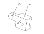
Fig. 1 is the structural representation of counterdie of the present utility model.
Fig. 2 is structural principle schematic diagram of the present utility model.
Fig. 3 is the structural representation of concentric contiguous block of the present utility model.
Be labeled as among the figure: 1, upper bolster, 2, punch pin with V-shaped hose, 3, die shoe, 4, supporting seat, 5, turnover panel, 6, contiguous block with one heart, 7, hinge block, 8, the buoyant device, 9, rotating shaft, 10, buoyant piece, 11, the power transmission pin, 12, spring, 13, end secondary screw, 14, groove, 15, concentric connecting hole, 16, sheet material.
The specific embodiment
Below in conjunction with accompanying drawing the utility model is further specified.
A kind of V-arrangement Bending Mould, comprise the corresponding upper die and lower die that arrange, patrix is made up of upper bolster 1 and the punch pin with V-shaped hose 2 that is arranged on the upper bolster 1, counterdie comprises die shoe 3, supporting seat 4, turnover panel 5, concentric contiguous block 6, hinge block 7 and buoyant device 8, the end face of die shoe 3 is provided with a groove 14, buoyant device 8 is located in the groove 14, two supporting seats 4 are set in parallel on the die shoe 3, and be positioned at the both sides of groove 14, two supporting seat 4 relative faces are an inclined-plane, two inclined-planes do not contact but V-shaped setting, the top of buoyant device 8 is between two inclined-planes, the end face of two supporting seats 4 is provided with two turnover panels that parallel 5, two turnover panels 5 and the 4 corresponding settings of two supporting seats, the axis of symmetry of the axis of symmetry of two turnover panels 5 and two supporting seats 4 is positioned at a perpendicular, the two ends of each turnover panel 5 all arrange a concentric contiguous block 6, the two ends of turnover panel 5 are fixed in the draw-in groove of concentric contiguous block 6, two concentric contiguous blocks 6 of two turnover panel 5 same ends are oppositely arranged, the opposite end of two concentric contiguous blocks 6 is equipped with a concentric connecting hole 15, two concentric contiguous blocks 6 concentric connecting hole 15 by separately is connected with rotating shaft 9 on the hinge block 7, and hinge block 7 is fixed on the die shoe 3.
Described buoyant device 8 comprises buoyant piece 10, power transmission pin 11 and the spring 12 that connects successively from top to bottom, and the lower end of buoyant device 8 is fixed in the groove 14 by ending secondary screw 13.
In forming process, the punch pin with V-shaped hose 2 that is fixed on the upper bolster 1 moves downward with punch press, contact with shaped sheet 16, under the effect of punch pin with V-shaped hose 2 power, two turnover panels 5 and separately the concentric contiguous block 6 of end be rotated down around rotating shaft 9 together, and then buoyant piece 10 is moved downward, power transmission pin 11 moves downward, spring 12 compressions.When turnover panel 5 is rotated down the place, inclined-plane of supporting seat 4, forming process is finished, sheet material 16 bending forming V-shapes, afterwards, upper bolster 1 moves upward under the drive of punch press, under the effect of spring 12 power, power transmission pin 11 and buoyant piece 10 move upward, and then drive turnover panel 5 around rotating shaft 9 rotations and move upward together, and each part resets, take out sheet material 16, begin new process.
Claims (2)
1. V-arrangement Bending Mould, comprise the corresponding upper die and lower die that arrange, it is characterized in that: patrix is made up of upper bolster (1) and the punch pin with V-shaped hose (2) that is arranged on the upper bolster (1), counterdie comprises die shoe (3), supporting seat (4), turnover panel (5), concentric contiguous block (6), hinge block (7) and buoyant device (8), the end face of die shoe (3) is provided with a groove (14), buoyant device (8) is located in the groove (14), two supporting seats (4) are set in parallel on the die shoe (3), and be positioned at the both sides of groove (14), the relative face of two supporting seats (4) is an inclined-plane, the end face of two supporting seats (4) is provided with two turnover panels that parallel (5), two turnover panels (5) and the corresponding setting of two supporting seats (4), the two ends of each turnover panel (5) all arrange a concentric contiguous block (6), the two ends of turnover panel (5) are fixed in the draw-in groove of concentric contiguous block (6), two concentric contiguous blocks (6) of the same end of two turnover panels (5) are oppositely arranged, the opposite end of two concentric contiguous blocks (6) is equipped with a concentric connecting hole (15), the concentric connecting hole (15) of two concentric contiguous blocks (6) by separately is connected with rotating shaft (9) on the hinge block (7), and hinge block (7) is fixed on the die shoe (3).
2. a kind of V-arrangement Bending Mould as claimed in claim 1, it is characterized in that: described buoyant device (8) comprises buoyant piece (10), power transmission pin (11) and the spring (12) that connects successively from top to bottom, and the lower end of buoyant device (8) is fixed in the groove (14) by ending secondary screw (13).
Priority Applications (1)
| Application Number | Priority Date | Filing Date | Title |
|---|---|---|---|
| CN 201320047109 CN203061703U (en) | 2013-01-29 | 2013-01-29 | V-shaped bending die |
Applications Claiming Priority (1)
| Application Number | Priority Date | Filing Date | Title |
|---|---|---|---|
| CN 201320047109 CN203061703U (en) | 2013-01-29 | 2013-01-29 | V-shaped bending die |
Publications (1)
| Publication Number | Publication Date |
|---|---|
| CN203061703U true CN203061703U (en) | 2013-07-17 |
Family
ID=48760529
Family Applications (1)
| Application Number | Title | Priority Date | Filing Date |
|---|---|---|---|
| CN 201320047109 Expired - Fee Related CN203061703U (en) | 2013-01-29 | 2013-01-29 | V-shaped bending die |
Country Status (1)
| Country | Link |
|---|---|
| CN (1) | CN203061703U (en) |
Cited By (3)
| Publication number | Priority date | Publication date | Assignee | Title |
|---|---|---|---|---|
| CN108580598A (en) * | 2017-12-26 | 2018-09-28 | 芜湖市恒浩机械制造有限公司 | A kind of V-arrangement sheet metal component punch forming device |
| CN109647939A (en) * | 2018-12-29 | 2019-04-19 | 苏州协朗精密机械有限公司 | A kind of Traceless bending die tool applied to plate |
| CN114653833A (en) * | 2022-04-15 | 2022-06-24 | 江苏奔宇车身制造有限公司 | Traceless bending die |
-
2013
- 2013-01-29 CN CN 201320047109 patent/CN203061703U/en not_active Expired - Fee Related
Cited By (4)
| Publication number | Priority date | Publication date | Assignee | Title |
|---|---|---|---|---|
| CN108580598A (en) * | 2017-12-26 | 2018-09-28 | 芜湖市恒浩机械制造有限公司 | A kind of V-arrangement sheet metal component punch forming device |
| CN109647939A (en) * | 2018-12-29 | 2019-04-19 | 苏州协朗精密机械有限公司 | A kind of Traceless bending die tool applied to plate |
| CN109647939B (en) * | 2018-12-29 | 2023-10-17 | 苏州协朗精密机械有限公司 | Be applied to no trace mould of bending of plate |
| CN114653833A (en) * | 2022-04-15 | 2022-06-24 | 江苏奔宇车身制造有限公司 | Traceless bending die |
Similar Documents
| Publication | Publication Date | Title |
|---|---|---|
| CN202779384U (en) | Punching die with convex dies capable of moving horizontally | |
| CN104139099A (en) | Plate bending forming mold | |
| CN204074947U (en) | New side pushes away pressing die | |
| CN202356516U (en) | One-step forming die for lithium battery aluminum cover plate | |
| CN201493401U (en) | Compensation-type press-forming combined die for semi-circular thick steel plate | |
| CN203061703U (en) | V-shaped bending die | |
| CN207668289U (en) | A kind of side piercing die | |
| CN203711612U (en) | Die for forming automobile plug | |
| CN204934350U (en) | A kind of mold members | |
| CN101758141A (en) | General stamping mould for automatic centering of plates with different widths | |
| CN208303640U (en) | A kind of automobile forming class stamping die for high-tension plates | |
| CN203281735U (en) | Once forming stamping die for brake pad tension spring connecting bent strip | |
| CN203002937U (en) | Double-wedged stamping mould | |
| CN102688942A (en) | Punching die for base adapter member | |
| CN202701152U (en) | Guide rail front plate forming die | |
| CN202367063U (en) | Large pressing plate die for bending machine | |
| CN202239180U (en) | Continuous mold for shell | |
| CN114192674A (en) | Rotary traceless bending die for mounting bracket of electric drive rear axle motor of automobile and machining process of rotary traceless bending die | |
| CN202752438U (en) | Scratch-free bending die | |
| CN202861135U (en) | Convex hull stamping die structure | |
| CN202725769U (en) | Automatic die-pressing die-cutting machine | |
| CN202845590U (en) | Crane bending plate press-forming die structure | |
| CN207695453U (en) | A kind of Blanking mold | |
| CN202316780U (en) | Mold structure for punching and molding head part of worm of spiral clamping hoop | |
| CN205270619U (en) | Individual spring pocket case |
Legal Events
| Date | Code | Title | Description |
|---|---|---|---|
| C14 | Grant of patent or utility model | ||
| GR01 | Patent grant | ||
| C17 | Cessation of patent right | ||
| CF01 | Termination of patent right due to non-payment of annual fee |
Granted publication date: 20130717 Termination date: 20140129 |