CN202676816U - A photoelectric coupling device, photoelectric coupling detection circuits, and an indication circuit - Google Patents
A photoelectric coupling device, photoelectric coupling detection circuits, and an indication circuit Download PDFInfo
- Publication number
- CN202676816U CN202676816U CN 201220219107 CN201220219107U CN202676816U CN 202676816 U CN202676816 U CN 202676816U CN 201220219107 CN201220219107 CN 201220219107 CN 201220219107 U CN201220219107 U CN 201220219107U CN 202676816 U CN202676816 U CN 202676816U
- Authority
- CN
- China
- Prior art keywords
- diode
- photoelectrical coupler
- current
- resistance
- input end
- Prior art date
- Legal status (The legal status is an assumption and is not a legal conclusion. Google has not performed a legal analysis and makes no representation as to the accuracy of the status listed.)
- Expired - Lifetime
Links
Images


Abstract
The utility model relates to a photoelectric coupling device comprising a diode D1', a diode D2, a diode D3, a diode D4, a photoelectric coupler, and a current-limiting resistor R42'. According to same polarities, the diode D2, the diode D3, and the diode D4 are successively connected in series. The anode of the diode D2 is connected with the cathode of the diode D1' and the first input end of the photoelectric coupler. The cathode of the diode D4 is connected with the anode of the diode D1' and the first end of the current-limiting resistor R42'. The second input end of the photoelectric coupler is connected with the second of the current-limiting resistor R42'. The utility model also relates to a photoelectric coupling detection circuit used for detecting power on/off of an AC load using AC, a photoelectric coupling detection circuit used for detecting an AC zero cross signal, and an indication circuit used for detecting power on/off of the AC load using AC and indicating the power on/off. The photoelectric coupling device reduces caloric power and increases safety performance.
Description
[technical field]
The utility model relates to optical coupling device, photoelectricity isolation detection circuit and bulletin circuit.
[background technology]
As shown in Figure 1, photoelectrical coupler (encapsulation of four pin) U4, its built-in light emitting diode and a phototriode, the first input end 1 of photoelectrical coupler, 2 contrapositions of the second input end are positive pole, the negative pole of light emitting diode, and the first output terminal 3 of photoelectrical coupler, 4 contrapositions of the second output terminal are collector, the emitter of phototriode.
Carry in this application the photoelectrical coupler of stating and be above-mentioned photoelectrical coupler.
See Fig. 2, the power on/off of the existing AC load by detecting use city's alternating current (220V/50Hz) in market is to carry out the bulletin circuit of bulletin to the user, comprise current-limiting resistance R42, diode D1, photoelectrical coupler U4, resistance R 43, electrochemical capacitor C27, single-chip microcomputer and bulletin module, the first end of current-limiting resistance R42 is connected negative pole and is connected with diode D1, photoelectrical coupler is attempted by the two ends of diode D1, the first input end of photoelectrical coupler is connected with the negative pole of diode D1, the second input end of photoelectrical coupler is connected with the positive pole of diode D1, first its working power of output termination of photoelectrical coupler, the second output terminal of photoelectrical coupler and resistance R 43, the positive pole of electrochemical capacitor C27 is connected successively, the positive pole of electrochemical capacitor C27, single-chip microcomputer and bulletin module are connected successively, the minus earth of electrochemical capacitor C27; This circuit with the positive pole of the second end of current-limiting resistance R42 and diode D1 as input end.
The principle of work of above-mentioned bulletin circuit is as follows: the two ends that the positive pole of the second end of current-limiting resistance R42 and diode D1 are connected to the load R0 that uses electric main; When AC power is in positive half period, electric current is from power supply L end minute two-way after K switch 1, one the tunnel flows back to power supply N through load R0 holds, power supply N end is flowed back to through current-limiting resistance R42, photoelectrical coupler U4 in another road, photoelectrical coupler U4 is in the conducting duty, then photoelectrical coupler U4 output electrical signals, electrochemical capacitor C27 is in charged state, and electrochemical capacitor C27 output high level is to single-chip microcomputer; When AC power was in negative half-cycle, electric current was from power supply N end minute two-way, and one the tunnel flows back to power supply L through load R0, K switch 1 holds, and power supply L end is flowed back to through diode D1, current-limiting resistance R42, K switch 1 in another road; Photoelectrical coupler U4 is in not on-state, electrochemical capacitor C27 is in discharge condition, and (by designing requirement, in a negative half-cycle, electrochemical capacitor C27 can not be discharged fully, need to continue to single-chip microcomputer output high level signal), electrochemical capacitor C27 output high level is to single-chip microcomputer; When AC power is in outage, photoelectrical coupler U4 is in not on-state, and electrochemical capacitor C27 is in discharge condition, and final electrochemical capacitor C27 can not export high level to single-chip microcomputer, Micro Controller Unit (MCU) driving bulletin module bulletin user, for example bulletin module is a warning circuit.
Wherein, as shown in Figure 3, above-mentioned bulletin circuit has comprised a general optical coupling device, comprise current-limiting resistance R42, diode D1, photoelectrical coupler U4, the first end of current-limiting resistance R42 is connected negative pole and is connected with diode D1, photoelectrical coupler U4 is attempted by the two ends of diode D1, the positive terminal of photoelectrical coupler is connected with the negative pole of diode D1, the negative pole end of photoelectrical coupler is connected with the positive pole of diode D1, and the second end of current-limiting resistance R42 and the positive pole of diode D1 are as the input end of optical coupling device.Wherein, the purpose of design of diode D1 is to prevent that photoelectrical coupler U4 is punctured by reverse voltage, diode D1 and photoelectrical coupler U4 built-in light emitting diode reverse, the purpose of design of current-limiting resistance R42 is to prevent that diode D1, photoelectrical coupler U4 pressurized from puncturing.
(above-mentioned photoelectricity isolation detection circuit for example when above-mentioned optical coupling device applies to alternating current, be connected in the interlock circuit and be, also connect with AC load), have following defective: the input terminal voltage of optical coupling device fluctuates with the fluctuation of alternating voltage, easily can't detect power supply signal if the selection of current-limiting resistance resistance is excessive, if the current-limiting resistance resistance is selected too small excessive photoelectrical coupler easily damage and the current-limiting resistance heating serious problems of causing of electric current that then exist.
[utility model content]
The technical problems to be solved in the utility model provides a kind of optical coupling device, has reduced thermal value, has improved security performance.
Above-mentioned technical matters solves by the following technical programs:
A kind of optical coupling device, it is characterized in that, comprise diode D1 ', diode D2, diode D3, diode D4, photoelectrical coupler and current-limiting resistance R42 ', diode D2, diode D3, diode D4 be successively series connection in the same way, the negative pole of the cathode connecting diode D1 ' of diode D2, the first input end of photoelectrical coupler, the negative pole of diode D4 connects the positive pole of diode D1 ', the first end of current-limiting resistance R42 ', and the second input end of photoelectrical coupler connects the second end of current-limiting resistance R42 '.
Also at the input end of photoelectrical coupler and meet a filter capacitor C29.
By such scheme as seen, the utlity model has two advantages: the one, utilize 3 general-purpose diodes to limit the input terminal voltage of photoelectrical coupler when the power supply positive-negative half-cycle, guarantee in the situation that voltage ripple of power network photoelectrical coupler voltage does not raise with line voltage, prevent that the optocoupler overvoltage from damaging; The 2nd, in the application scenario of load current less (electric current is less than diode D1 ' rated current), the most of voltage of load has been shared in the internal resistance that utilizes AC load itself to have, can save industry high-power current-limiting resistance of series connection before photoelectrical coupler commonly used, avoid the extra power consumption that produces of current-limiting resistance, anti-locking apparatus lost efficacy because resistance heating damages, and improved circuit reliability.
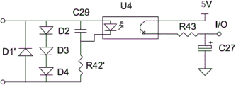
The utility model also provides a kind of photoelectricity isolation detection circuit of power on/off of the AC load for detection of using alternating current, it is characterized in that, comprise optical coupling device, resistance R 43 and electrochemical capacitor C27, optical coupling device comprises diode D1 ', diode D2, diode D3, diode D4, photoelectrical coupler and current-limiting resistance R42 ', diode D2, diode D3, diode D4 is successively series connection in the same way, the negative pole of the cathode connecting diode D1 ' of diode D2, the first input end of photoelectrical coupler, the negative pole of diode D4 connects the positive pole of diode D1 ', the first end of current-limiting resistance R42 ', the second input end of photoelectrical coupler U4 connects the second end of current-limiting resistance R42 '; The first output terminal of photoelectrical coupler connects working power, and the second output terminal of photoelectrical coupler is connected the minus earth of electrochemical capacitor C27 successively with the positive pole of resistance R 43, electrochemical capacitor C27.Also at the input end of photoelectrical coupler and meet a filter capacitor C29.Testing circuit relatively the utlity model has higher security performance.
The utility model also provides a kind of power on/off of the AC load for detection of using alternating current and the bulletin circuit that carries out bulletin, it is characterized in that, comprise optical coupling device, resistance R 43, electrochemical capacitor C27, single-chip microcomputer and bulletin module, optical coupling device comprises diode D1 ', diode D2, diode D3, diode D4, photoelectrical coupler and current-limiting resistance R42 ', diode D2, diode D3, diode D4 is successively series connection in the same way, the negative pole of the cathode connecting diode D1 ' of diode D2, the first input end of photoelectrical coupler, the negative pole of diode D4 connects the positive pole of diode D1 ', the first end of current-limiting resistance R42 ', the second input end of photoelectrical coupler U4 connects the second end of current-limiting resistance R42 '; The first output terminal of photoelectrical coupler connects working power, the second output terminal of photoelectrical coupler is connected successively with the positive pole of resistance R 43, electrochemical capacitor C27, the positive pole of electrochemical capacitor C27, single-chip microcomputer and bulletin module are connected successively, the minus earth of electrochemical capacitor C27.Also at the input end of photoelectrical coupler and meet a filter capacitor C29.Testing circuit relatively the utlity model has higher security performance.
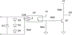
The utility model also provides a kind of photoelectricity isolation detection circuit for detection of the alternating current zero crossing signal, it is characterized in that, comprise optical coupling device, resistance R 44, resistance R 45, resistance R 46 and triode Q1, optical coupling device comprises diode D1 ', diode D2, diode D3, diode D4, photoelectrical coupler and current-limiting resistance R42 ', diode D2, diode D3, diode D4 is successively series connection in the same way, the negative pole of the cathode connecting diode D1 ' of diode D2, the first input end of photoelectrical coupler U4, the negative pole of diode D4 connects the positive pole of diode D1 ', the first end of current-limiting resistance R42 ', the second input end of photoelectrical coupler U4 connects the second end of current-limiting resistance R42 '; The first output terminal of photoelectrical coupler U4 connects working power, the second output terminal of photoelectrical coupler U4 is connected with the first end of the first end of resistance R 44, resistance R 45, the second end ground connection of resistance R 44, the base stage of the second end connecting triode Q1 of resistance R 45, the collector of triode Q1 connects the working power of 5V, the grounded emitter of triode Q1 by resistance R 46.Also at the input end of photoelectrical coupler and meet a filter capacitor C29.Testing circuit relatively the utlity model has higher security performance.
[description of drawings]
Fig. 1 is the structural representation of photoelectrical coupler in the background technology;
Fig. 2 is the structural representation of bulletin circuit in the background technology;
Fig. 3 is the structural representation of optical coupling device in the background technology;
Fig. 4 is the structural representation of embodiment one optical coupling device;
Fig. 5 is the structural representation of embodiment two photoelectricity isolation detection circuits;
Fig. 6 is the application schematic diagram of embodiment two bulletin circuit;
Fig. 7 is the application schematic diagram of embodiment three bulletin circuit;
Fig. 8 is the structural representation of embodiment four photoelectricity isolation detection circuits.
[embodiment]
Embodiment one
As shown in Figure 4, the optical coupling device that the present embodiment provides comprises diode D1 ', diode D2, diode D3, diode D4, photoelectrical coupler U4 and current-limiting resistance R42 ', diode D2, diode D3, in the same way successively series connection of diode D4 (is the positive pole of the negative pole connection diode D3 of diode D2, the negative pole of diode D3 connects the positive pole of diode D4), the negative pole of the cathode connecting diode D1 ' of diode D2, the first input end of photoelectrical coupler U4, the negative pole of diode D4 connects the positive pole of diode D1 ', the first end of current-limiting resistance R42 ', the second input end of photoelectrical coupler U4 connects the second end of current-limiting resistance R42 '; The positive pole of diode D1 ', negative pole correspondence are as first input end, second input end of this device.
Wherein, also at the input end of photoelectrical coupler U4 and meet a filter capacitor C29.
This optical coupling device is applied in the alternating circuit (concrete connected mode: be connected in series with AC load) and has the following advantages: at 3 diode D2, D3, D4(IN4007) in the situation of forward conduction, each diode drop is about 0.7 volt, 3 diode D2, D3, totally 2 volts approximately of D4 pressure drops, these 3 diodes provide an AC supply voltage to photoelectrical coupler U4 with can be in positive half period at the power supply of AC load after photoelectrical coupler U4 input end is in parallel the time, can prevent that photoelectrical coupler U4 is because of the too high damage of pressure drop as photoelectrical coupler U4 voltage clamping circuit again; When the power supply of AC load was in negative half-cycle, electric current flowed back to power supply L end from the N end through load, diode D1 '; Only have an appointment 0.7 volt because of the D1 pressure drop again, less than the built-in light emitting diode breakdown reverse voltage of photoelectrical coupler U4, not conducting of photoelectrical coupler U4, thus guarantee photoelectrical coupler U4 trouble free service when the power-half cycle.
Embodiment two
As shown in Figure 5, the present embodiment provides a kind of optical coupling device based on embodiment one and for detection of the photoelectricity isolation detection circuit of the power on/off of the AC load of using alternating current, specifically comprise optical coupling device, resistance R 43 and electrochemical capacitor C27, optical coupling device comprises diode D1 ', diode D2, diode D3, diode D4, photoelectrical coupler U4 and current-limiting resistance R42 ', diode D2, diode D3, in the same way successively series connection of diode D4 (is the positive pole of the negative pole connection diode D3 of diode D2, the negative pole of diode D3 connects the positive pole of diode D4), the negative pole of the cathode connecting diode D1 ' of diode D2, the first input end of photoelectrical coupler U4, the negative pole of diode D4 connects the positive pole of diode D1 ', the first end of current-limiting resistance R42 ', the second input end of photoelectrical coupler U4 connects the second end of current-limiting resistance R42 '; The first output terminal of photoelectrical coupler U4 connects working power, and the second output terminal of photoelectrical coupler U4 is connected successively with the positive pole of resistance R 43, electrochemical capacitor C27; The positive pole of diode D1 ', negative pole correspondence are as first total input end, second total input end of this photoelectricity isolation detection circuit.
Wherein, also at the input end of photoelectrical coupler U4 and meet a filter capacitor C29.
When this photoelectricity isolation detection circuit detects the power on/off of the AC load of using alternating current, be to be connected in series with AC load; When AC power is in positive half period, electric current enters behind first total input end and divides two-way, one the tunnel flows back to second total input end through diode D2, D3, D4, second total input end is flowed back to through photoelectrical coupler U4, current-limiting resistance R42 ' in another road, photoelectrical coupler U4 is in the conducting duty, then photoelectrical coupler U4 output electrical signals, electrochemical capacitor C27 is in charged state, the positive pole output high level signal of electrochemical capacitor C27; When AC power is in negative half-cycle, electric current flows back to first total input end from second total input end through diode D1 ', photoelectrical coupler U4 is in not on-state, electrochemical capacitor C27 is in discharge condition (by designing requirement, in a negative half-cycle, electrochemical capacitor C27 can not be discharged fully), the positive pole of electrochemical capacitor C27 is still exported high level signal; When AC power was in outage, photoelectrical coupler U4 was in not on-state, and electrochemical capacitor C27 is in discharge condition, and the positive pole of final electrochemical capacitor C27 can not be exported high level signal.
This photoelectricity isolation detection circuit utilizes electrochemical capacitor C27 just so that still can keep low level output after high level output is distinguished outage in each the energising cycle that exchanges, thereby the power on/off that realizes alternating current detects.
In this circuit because the pressure limiting effect of 3 diode D2, D3, D4, so that photoelectrical coupler U4 is operated under the load rated safety voltage, and most alternating voltage transferred on the AC load (because after the deboost of three diode D2, D3, D4 is arranged, the resistance value of current-limiting resistance R42 ' does not require greatly, therefore, current-limiting resistance R42 ' thermal value is very little), improved the reliability of circuit.
Embodiment three
As shown in Figure 6, the present embodiment provides a kind of bulletin circuit of the photoelectricity isolation detection circuit based on embodiment two, it comprises photoelectricity isolation detection circuit, single-chip microcomputer and the bulletin module of embodiment two, the positive pole of electrochemical capacitor C27, single-chip microcomputer and bulletin module are connected successively, the minus earth of electrochemical capacitor C27; The positive pole of diode D1 ', negative pole correspondence are as first total input end, second total input end of this bulletin circuit.
This bulletin electric circuit inspection electric circuit inspection use alternating current AC load power on/off and when carrying out that the user carried out bulletin, be to be connected in series with AC load; Concrete principle of work is that in the normal power-up of alternating current, electrochemical capacitor C27 output high level signal is to single-chip microcomputer, after the alternating current outage, single-chip microcomputer can't detect the high level signal of electrochemical capacitor C27 output, just drives bulletin module bulletin user, and for example bulletin module is a warning circuit.
As shown in Figure 7, this bulletin circuit realizes that by the power on/off that detects AC load (it comprises that a water that is used for heating water tank makes water vapor volatilization humidification humidification heater to electric heater, be AC load R11) dry combustion method detect, specifically, AC load R11 and the photoelectricity isolation detection circuit with electric heater is connected in series; When the overheated dry combustion method of humidification heater R11, the temperature controller K2 of electric heater disconnects, and single-chip microcomputer detects low level signal and makes driving bulletin module, and prompting user need add water again.
Embodiment four
As shown in Figure 8, the present embodiment provides a kind of photoelectricity isolation detection circuit for detection of the alternating current zero crossing signal, specifically comprise optical coupling device, resistance R 44, resistance R 45, resistance R 46 and triode Q1, optical coupling device comprises diode D1 ', diode D2, diode D3, diode D4, photoelectrical coupler U4 and current-limiting resistance R42 ', diode D2, diode D3, in the same way successively series connection of diode D4 (is the positive pole of the negative pole connection diode D3 of diode D2, the negative pole of diode D3 connects the positive pole of diode D4), the negative pole of the cathode connecting diode D1 ' of diode D2, the first input end of photoelectrical coupler U4, the negative pole of diode D4 connects the positive pole of diode D1 ', the first end of current-limiting resistance R42 ', the second input end of photoelectrical coupler U4 connects the second end of current-limiting resistance R42 '; The first output terminal of photoelectrical coupler U4 connects working power, the second output terminal of photoelectrical coupler U4 is connected with the first end of the first end of resistance R 44, resistance R 45, the second end ground connection of resistance R 44, the base stage of the second end connecting triode Q1 of resistance R 45, the collector of triode Q1 connects the working power of 5V, the grounded emitter of triode Q1 by resistance R 46; The voltage signal of the collector of triode Q1 is as the output signal of this device; The positive pole of diode D1 ', negative pole correspondence are as first total input end, second total input end of this device.
Wherein, also at the input end of photoelectrical coupler U4 and meet a filter capacitor C29.
When this photoelectricity isolation detection circuit detects the alternating current zero crossing signal, be to be connected in series with AC load; When alternating current is in positive half cycle, photoelectrical coupler U4 conducting, the voltage signal of the collector of triode Q1 is low level; When alternating current is in negative half period, not conducting of photoelectrical coupler U4, the voltage signal of the collector of triode Q1 is high level; This photoelectricity isolation detection circuit is by exporting high-low level with expression alternating current zero crossing signal.
The utility model is not limited to above-described embodiment, based on simple replacement above-described embodiment, that do not make creative work, should belong to the scope that the utility model discloses.
Claims (8)
1. optical coupling device, it is characterized in that, comprise diode D1 ', diode D2, diode D3, diode D4, photoelectrical coupler and current-limiting resistance R42 ', diode D2, diode D3, diode D4 be successively series connection in the same way, the negative pole of the cathode connecting diode D1 ' of diode D2, the first input end of photoelectrical coupler, the negative pole of diode D4 connects the positive pole of diode D1 ', the first end of current-limiting resistance R42 ', and the second input end of photoelectrical coupler connects the second end of current-limiting resistance R42 '.
2. optical coupling device according to claim 1 is characterized in that, also at the input end of photoelectrical coupler and meet a filter capacitor C29.
3. photoelectricity isolation detection circuit for detection of the power on/off of the AC load of using alternating current, it is characterized in that, comprise optical coupling device, resistance R 43 and electrochemical capacitor C27, optical coupling device comprises diode D1 ', diode D2, diode D3, diode D4, photoelectrical coupler and current-limiting resistance R42 ', diode D2, diode D3, diode D4 is successively series connection in the same way, the negative pole of the cathode connecting diode D1 ' of diode D2, the first input end of photoelectrical coupler, the negative pole of diode D4 connects the positive pole of diode D1 ', the first end of current-limiting resistance R42 ', the second input end of photoelectrical coupler connects the second end of current-limiting resistance R42 '; The first output terminal of photoelectrical coupler connects working power, and the second output terminal of photoelectrical coupler is connected the minus earth of electrochemical capacitor C27 successively with the positive pole of resistance R 43, electrochemical capacitor C27.
4. photoelectricity isolation detection circuit according to claim 3 is characterized in that, also at the input end of photoelectrical coupler and meet a filter capacitor C29.
5. one kind for detection of the power on/off of the AC load of using alternating current and the bulletin circuit that carries out bulletin, it is characterized in that, comprise optical coupling device, resistance R 43, electrochemical capacitor C27, single-chip microcomputer and bulletin module, optical coupling device comprises diode D1 ', diode D2, diode D3, diode D4, photoelectrical coupler and current-limiting resistance R42 ', diode D2, diode D3, diode D4 is successively series connection in the same way, the negative pole of the cathode connecting diode D1 ' of diode D2, the first input end of photoelectrical coupler, the negative pole of diode D4 connects the positive pole of diode D1 ', the first end of current-limiting resistance R42 ', the second input end of photoelectrical coupler connects the second end of current-limiting resistance R42 '; The first output terminal of photoelectrical coupler connects working power, the second output terminal of photoelectrical coupler is connected successively with the positive pole of resistance R 43, electrochemical capacitor C27, the positive pole of electrochemical capacitor C27, single-chip microcomputer and bulletin module are connected successively, the minus earth of electrochemical capacitor C27.
6. bulletin circuit according to claim 5 is characterized in that, also at the input end of photoelectrical coupler and meet a filter capacitor C29.
7. photoelectricity isolation detection circuit for detection of the alternating current zero crossing signal, it is characterized in that, comprise optical coupling device, resistance R 44, resistance R 45, resistance R 46 and triode Q1, optical coupling device comprises diode D1 ', diode D2, diode D3, diode D4, photoelectrical coupler and current-limiting resistance R42 ', diode D2, diode D3, diode D4 is successively series connection in the same way, the negative pole of the cathode connecting diode D1 ' of diode D2, the first input end of photoelectrical coupler, the negative pole of diode D4 connects the positive pole of diode D1 ', the first end of current-limiting resistance R42 ', the second input end of photoelectrical coupler connects the second end of current-limiting resistance R42 '; The first output terminal of photoelectrical coupler connects working power, the second output terminal of photoelectrical coupler is connected with the first end of the first end of resistance R 44, resistance R 45, the second end ground connection of resistance R 44, the base stage of the second end connecting triode Q1 of resistance R 45, the collector of triode Q1 connects working power, the grounded emitter of triode Q1 by resistance R 46.
8. photoelectricity isolation detection circuit according to claim 7 is characterized in that, also at the input end of photoelectrical coupler and meet a filter capacitor C29.
Priority Applications (1)
| Application Number | Priority Date | Filing Date | Title |
|---|---|---|---|
| CN 201220219107 CN202676816U (en) | 2012-05-15 | 2012-05-15 | A photoelectric coupling device, photoelectric coupling detection circuits, and an indication circuit |
Applications Claiming Priority (1)
| Application Number | Priority Date | Filing Date | Title |
|---|---|---|---|
| CN 201220219107 CN202676816U (en) | 2012-05-15 | 2012-05-15 | A photoelectric coupling device, photoelectric coupling detection circuits, and an indication circuit |
Publications (1)
| Publication Number | Publication Date |
|---|---|
| CN202676816U true CN202676816U (en) | 2013-01-16 |
Family
ID=47497713
Family Applications (1)
| Application Number | Title | Priority Date | Filing Date |
|---|---|---|---|
| CN 201220219107 Expired - Lifetime CN202676816U (en) | 2012-05-15 | 2012-05-15 | A photoelectric coupling device, photoelectric coupling detection circuits, and an indication circuit |
Country Status (1)
| Country | Link |
|---|---|
| CN (1) | CN202676816U (en) |
Cited By (8)
| Publication number | Priority date | Publication date | Assignee | Title |
|---|---|---|---|---|
| CN103135039A (en) * | 2013-02-06 | 2013-06-05 | 王翥 | Power supply line fault monitoring device |
| CN105572523A (en) * | 2014-10-09 | 2016-05-11 | 中兴通讯股份有限公司 | AC detection circuit |
| CN106383312A (en) * | 2016-12-01 | 2017-02-08 | 北京简佑科技有限公司 | Motor state detection circuit and motor state display device |
| CN106569015A (en) * | 2015-10-13 | 2017-04-19 | 泰科电子(上海)有限公司 | AC load detection circuit |
| CN110456263A (en) * | 2019-08-02 | 2019-11-15 | 恒大智慧充电科技有限公司 | A kind of relay is adhered detection circuit, device and its detection method |
| CN111796140A (en) * | 2020-06-30 | 2020-10-20 | 上海宏力达信息技术股份有限公司 | Detection circuit for simultaneously detecting zero crossing point and stopping power recovery |
| CN111795714A (en) * | 2019-04-03 | 2020-10-20 | 深圳市正弦电气股份有限公司 | ABZ differential encoder detection circuit without UVW magnetic pole signal |
| CN112986794A (en) * | 2021-01-25 | 2021-06-18 | 中国电子科技集团公司第二十九研究所 | Pulse matching load fault detection circuit and method |
-
2012
- 2012-05-15 CN CN 201220219107 patent/CN202676816U/en not_active Expired - Lifetime
Cited By (11)
| Publication number | Priority date | Publication date | Assignee | Title |
|---|---|---|---|---|
| CN103135039A (en) * | 2013-02-06 | 2013-06-05 | 王翥 | Power supply line fault monitoring device |
| CN105572523A (en) * | 2014-10-09 | 2016-05-11 | 中兴通讯股份有限公司 | AC detection circuit |
| CN106569015A (en) * | 2015-10-13 | 2017-04-19 | 泰科电子(上海)有限公司 | AC load detection circuit |
| CN106569015B (en) * | 2015-10-13 | 2019-10-18 | 泰科电子(上海)有限公司 | AC load detection circuit |
| CN106383312A (en) * | 2016-12-01 | 2017-02-08 | 北京简佑科技有限公司 | Motor state detection circuit and motor state display device |
| CN106383312B (en) * | 2016-12-01 | 2023-06-27 | 北京简佑科技有限公司 | Motor state detection circuit and motor state display device |
| CN111795714A (en) * | 2019-04-03 | 2020-10-20 | 深圳市正弦电气股份有限公司 | ABZ differential encoder detection circuit without UVW magnetic pole signal |
| CN110456263A (en) * | 2019-08-02 | 2019-11-15 | 恒大智慧充电科技有限公司 | A kind of relay is adhered detection circuit, device and its detection method |
| CN111796140A (en) * | 2020-06-30 | 2020-10-20 | 上海宏力达信息技术股份有限公司 | Detection circuit for simultaneously detecting zero crossing point and stopping power recovery |
| CN111796140B (en) * | 2020-06-30 | 2023-06-30 | 上海宏力达信息技术股份有限公司 | Detection circuit for simultaneously detecting zero crossing point and stopping and restoring electricity |
| CN112986794A (en) * | 2021-01-25 | 2021-06-18 | 中国电子科技集团公司第二十九研究所 | Pulse matching load fault detection circuit and method |
Similar Documents
| Publication | Publication Date | Title |
|---|---|---|
| CN202676816U (en) | A photoelectric coupling device, photoelectric coupling detection circuits, and an indication circuit | |
| CN204631181U (en) | The testing circuit of a kind of rechargeable battery positive and negative electrode reversal connection | |
| CN202917976U (en) | Protective device of solar energy LED power supply input polarity reversal connection | |
| CN102801138B (en) | Light-emitting diode (LED) over current protection circuit and light fitting | |
| CN105372480A (en) | Over voltage, under voltage and phase failure detection circuit for charging pile | |
| CN205812466U (en) | LED drives control circuit | |
| CN101394135B (en) | Control system and controller power source for electric appliance | |
| CN203535107U (en) | Low power AC power-off alarming circuit | |
| CN208522519U (en) | A kind of photovoltaic power generation electric storage device | |
| CN201590934U (en) | Ultraviolet lamp failure detection circuit and device | |
| CN201707398U (en) | Three-phase power supply input open-phase detecting circuit | |
| CN104935061A (en) | Cell charging prompt circuit and lamp | |
| CN204720702U (en) | A kind of voltage fluctuation protection alarm socket | |
| CN204269797U (en) | A kind of power supply output detection circuit | |
| CN203167355U (en) | LED driver preventing LED from flickering | |
| CN103475074B (en) | Unloaded low-loss battery charger | |
| CN203205828U (en) | LED driving power supply input overvoltage protection circuit | |
| CN106771777B (en) | Inverter driving signal detection device of frequency converter | |
| CN204651888U (en) | A kind of Multi-functional safety electricity-using protection system | |
| CN204719123U (en) | A kind of overvoltage undervoltage detection circuit | |
| CN109347314A (en) | Electric leadage circuit more than high voltage ac/dc with defencive function | |
| CN213879341U (en) | Intelligent identification quick-charging power type heating control device for electric heating product | |
| CN204859676U (en) | LED drive arrangement | |
| CN202773140U (en) | Backlight LED drive protection circuit and television set | |
| CN206807828U (en) | A kind of conversion equipment |
Legal Events
| Date | Code | Title | Description |
|---|---|---|---|
| C14 | Grant of patent or utility model | ||
| GR01 | Patent grant | ||
| CX01 | Expiry of patent term |
Granted publication date: 20130116 |
|
| CX01 | Expiry of patent term |