CN202580864U - LED (light-emitting diode) fluorescent tube - Google Patents
LED (light-emitting diode) fluorescent tube Download PDFInfo
- Publication number
- CN202580864U CN202580864U CN2012202372486U CN201220237248U CN202580864U CN 202580864 U CN202580864 U CN 202580864U CN 2012202372486 U CN2012202372486 U CN 2012202372486U CN 201220237248 U CN201220237248 U CN 201220237248U CN 202580864 U CN202580864 U CN 202580864U
- Authority
- CN
- China
- Prior art keywords
- shell
- fluorescent tube
- led fluorescent
- lower casing
- buckle
- Prior art date
- Legal status (The legal status is an assumption and is not a legal conclusion. Google has not performed a legal analysis and makes no representation as to the accuracy of the status listed.)
- Expired - Lifetime
Links
Images


Landscapes
- Arrangement Of Elements, Cooling, Sealing, Or The Like Of Lighting Devices (AREA)
Abstract
The utility model discloses an LED (light-emitting diode) fluorescent tube which comprises a first shell and a second shell, wherein the first shell forms a containing space and comprises an upper shell and a lower shell; the lower shell is provided with an inner wall and an outer wall; the second shell is positioned in the containing space and clung to the inner wall of the lower shell; the first shell is plastic; and the second shell is metal. The LED fluorescent tube not only can dissipate the heat fast, but also is safe and reliable.
Description
Technical field
The utility model relates to a kind of lighting, relates in particular to a kind of LED fluorescent tube.
Background technology
Along with the development of LED technology, LED is also extensive day by day in the application of lighting field.Advantages such as now, to have energy consumption little because of the LED fluorescent lamp, and energy conversion efficiency is high, and the life-span is long, Environmental protection lamp and replacement gradually like common fluorescent lamps such as fluorescence fluorescent lamps, and is applied in the daily life.Along with LED is widely used, people also improve the requirement of LED lamp day by day.
So, traditional LED fluorescent tube mainly is made up of plastic lamp shade of the first half and the metal shell of the latter half, also has the shell of a small amount of LED fluorescent tube and lampshade to process with plastic material fully.With the purpose of metal as the part of shell, mainly be because its good heat dissipation effect, if but metal shell directly touched by the people; Then get an electric shock easily, security is not high, and head it off is generally considered from two aspects traditionally; On the one hand, attempt to avoid this problem from power supply, but no matter be that the employing insulating power supply also is non-insulating power supply; All can not guarantee absolute security, on the other hand, the whole casing of LED fluorescent tube is processed with plastic material; But its radiating effect is not good, and the heat that produces during LED work can't discharge effectively, causes reduce greatly service life.
Therefore, be badly in need of proposing a kind of new LED fluorescent tube to overcome the defective that the security of traditional LED lamp is not high or heat dispersion is not good.
The utility model content
The technical problem that the utility model will solve is to overcome the not deficiency of good existence of the not high or heat dispersion of above-mentioned traditional LED fluorescent tube security, and proposes a kind of new LED fluorescent tube, and it comprises,
One first shell, this first shell forms a spatial accommodation, and this first shell comprises shell and lower casing, and wherein, this lower casing has an inwall and an outer wall; And
One second shell, this second shell are positioned at this spatial accommodation and are close to the inwall of this lower casing, and wherein this first shell is a plastic casing, and this second shell is a metal shell.
In one embodiment, said second shell is connected with the lower casing engaging.
In one embodiment, said second shell is connected with last shell engaging.
In one embodiment, said second shell has draw-in groove, and the said shell of going up has last buckle, and said lower casing has following buckle, and the said buckle and said buckle down and said draw-in groove gone up fastens.
In one embodiment, said upward buckle and said buckle down are sticked in same said draw-in groove.
In one embodiment, have a plurality of undulatory concaveconvex structures that are on the outer wall of the lower casing of this first shell.
In one embodiment, said first shell is a circular housing.
In one embodiment, said second shell have one be used for support circuit plate and LED lamp pearl gripper shoe.
In one embodiment; One of them processes said second shell by aluminium, copper, titanium, aluminium alloy, copper alloy, kirsite or titanium alloy, and one of them processes said first shell by Merlon (PC), polymethyl methacrylate (PMMA), PETG (PET), polyvinyl chloride (PVC) or polystyrene (PS).
The LED fluorescent lamp of the utility model is through establish a metal shell again in the all-plastic shell, it can improve security performance again by quick heat radiating.
Description of drawings
Fig. 1 is the cross section structure sketch map of the utility model LED fluorescent tube.
Fig. 2 is the first shell cross section structure sketch map of the utility model LED fluorescent tube.
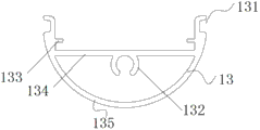
Fig. 3 is the second shell cross section structure sketch map of the utility model LED fluorescent tube.
Fig. 4 to Fig. 6 is the schematic flow sheet that the utility model first shell and second shell fasten.
The specific embodiment
For principle and the structure that further specifies the utility model, combine accompanying drawing that the preferred embodiment of the utility model is elaborated at present.
Please with reference to Fig. 1, it is the cross section structure sketch map of the utility model LED fluorescent tube.The utility model LED fluorescent tube 10 comprises one first shell 11, and this first shell 11 forms a spatial accommodation 12, and this first shell 11 comprises shell 112 and lower casing 114, and wherein, this lower casing 112 has an inwall 1101 and an outer wall 1102; And one second shell 13, its second shell 13 is positioned at this spatial accommodation 12 and is close to the inwall 1101 of this lower casing 114.
Please with reference to Fig. 2, it is the first shell cross section structure sketch map of the utility model LED fluorescent tube.Please merge with reference to figure 1; First shell 11 comprises the last shell 112 and lower casing 114 of two semicirculars in shape that can independently separate, and last shell 112 can be processed by transparent material, and its semicircular both ends are provided with the last buckle 1121 of direction transverse projections in shell; Lower casing 114 can be processed by light transmissive material or light-proof material; Have a plurality of undulatory concaveconvex structures that are on its outer wall 1103, increase the surface of outer wall 1103 and contacting of extraneous air, the heat that produces when making the work of LED fluorescent lamp is dispersed in the air fully apace; To improve the heat heat convection efficient in the fluorescent tube effectively; The semicircular both ends of lower casing 114 are provided with the following buckle 1141 of direction transverse projections in shell equally, first shell 11 that last shell 112 and lower casing 114 capable of being combined are rounded, and this first shell 11 is made of plastics; These plastics comprise by Merlon (PC), polymethyl methacrylate (PMMA), PETG (PET), polyvinyl chloride (PVC) or polystyrene materials such as (PS); But be not limited to this, under all prerequisites that does not break away from the utility model design, that makes anyly possibly be out of shape or substitute the scope that all belongs to the utility model protection.In a preferred embodiment, this plastic casing is the PC shell.
Please with reference to Fig. 3, Fig. 3 is the second shell cross section structure sketch map of the utility model LED fluorescent tube.Second shell 13 comprises an arc shell 135; On this arc shell 135, be provided with the gripper shoe 134 at a connection arc shell 135 two ends; Be provided with the screwed hole 132 that connects LED fluorescent tube both sides capping (not shown) at the middle part of gripper shoe 134; Above gripper shoe 134, be provided with two screens 133 that are parallel to gripper shoe 134, in addition, the both ends of second shell 13 respectively be provided with one laterally towards groove 131.
What need explanation is; The shape of said first shell 11 of above embodiment and second shell 13 is not limited to this embodiment; For example; The shape of first shell 11 and second shell 13 also can be triangle, rectangle, other shapes such as fan-shaped, and under all prerequisites that does not break away from the utility model design, that makes anyly possibly be out of shape or substitute the scope that all belongs to the utility model protection.
The utility model also provides a kind of construction method of LED fluorescent tube, and it comprises one first shell is set, and this first shell forms a spatial accommodation, and this first shell comprises shell and lower casing, and wherein, this lower casing has an inwall and an outer wall; And one second shell is set, and this second shell is positioned at this spatial accommodation and is close to the inwall of this lower casing, and wherein this first shell is a plastic casing, and this second shell is a metal shell.For specifying its construction method, please with reference to Fig. 4 to Fig. 6, Fig. 4 to Fig. 6 is the schematic flow sheet that the utility model first shell and second shell fasten.And please before engaging first shell 11 and second shell 13, will be mounted to the circuit board 15 that LED lamp pearl 14 is connected on the gripper shoe 134 earlier simultaneously with reference to Fig. 1; Circuit board 15 is just in time blocked in the screens 133 of the top of gripper shoe 134, makes it be positioned can upwards not bounce on the gripper shoe 134, then; The following buckle 1141 of one end of lower casing 114 alignd with the groove 131 of second shell, 13 1 ends fasten; Buckle 1141 is snapped in the groove 131, and slightly firmly extruding then fastens following buckle 1141 and the groove 131 of second shell, 13 other ends of the other end of lower casing 114; At this moment; The inwall that is positioned at lower casing 114 1101 of first shell 11 and the outer wall 137 of second shell 13 are combined closely, and form snap-in structure as shown in Figure 5, afterwards; The last buckle 1121 of shell 112 1 ends aligns with the groove 131 of second shell, 13 1 ends and fastens on first shell 11; Buckle 1121 is snapped in the groove 131, and slightly firmly extruding fastens the last buckle 1121 of shell 112 1 ends and the groove 131 of second shell, 13 other ends then; At this moment, the following buckle 1141 of the last buckle 1121 of last shell 112 1 ends and lower casing 114 1 ends is sticked in the same groove 131 of second shell, 13 1 ends.After combination is accomplished; Form LED fluorescent tube structure shown in Figure 1; Last shell 112 and lower casing 114 are with after second shell 13 engages; Form a circular housing (i.e. first shell 11), this circular housing forms a spatial accommodation 12, the second shells 13 and is located at this spatial accommodation 12 and is close to first shell 11.
Because the structure of the LED fluorescent tube that the utility model adopts is: in the all-plastic shell, add the inwall that a metal shell and metal shell are close to plastic casing again; Therefore; The utility model has solved LED fluorescent tube heat dissipation problem on the one hand, has improved security on the other hand.More specifically, metal shell is as the conductor of heat, during the work of LED fluorescent lamp; The heat energy of its generation is delivered on this metal shell fast, and metal shell closely contacts with plastic casing, makes heat to be delivered to fully apace on the plastic casing; Plastic casing is dispersed into heat in the air through heat convection and radiation heat transfer, realizes the quick heat radiating of LED fluorescent tube, on the other hand; What human body can touch is the plastic shell part of LED fluorescent tube, and it has avoided potential safety hazards such as electric shock or scald, and its security performance is good; Therefore, the LED fluorescent tube of the utility model not only is fit to insulating power supply, and is fit to non-insulating power supply too.
In addition, the utility model adopts the mode of engaging that metal shell is closely contacted with plastic casing, and this engaging mode is simple to operate and engaging back metal shell combines with plastic casing firmly, reliability is high.
The above is merely the preferable possible embodiments of the utility model, and the protection domain of unrestricted the utility model.The equivalent structure that all utilization the utility model specifications and accompanying drawing content have been done changes, and all is included in the protection domain of the utility model.
Claims (9)
1. a LED fluorescent tube is characterized in that, comprising:
One first shell, this first shell forms a spatial accommodation, and this first shell comprises shell and lower casing, and wherein, this lower casing has an inwall and an outer wall; And
One second shell, this second shell are positioned at this spatial accommodation and are close to the inwall of this lower casing, and wherein this first shell is a plastic casing, and this second shell is a metal shell.
2. LED fluorescent tube as claimed in claim 1 is characterized in that, said second shell is connected with the lower casing engaging.
3. LED fluorescent tube as claimed in claim 1 is characterized in that, said second shell is connected with last shell engaging.
4. LED fluorescent tube as claimed in claim 1 is characterized in that, said second shell has draw-in groove, and the said shell of going up has last buckle, and said lower casing has following buckle, and the said buckle and said buckle down and said draw-in groove gone up fastens.
5. LED fluorescent tube as claimed in claim 4 is characterized in that, said upward buckle and said buckle down are sticked in same said draw-in groove.
6. LED fluorescent tube as claimed in claim 1 is characterized in that, has a plurality of undulatory concaveconvex structures that are on the outer wall of the lower casing of this first shell.
7. LED fluorescent tube as claimed in claim 1 is characterized in that, said first shell is a circular housing.
8. LED fluorescent tube as claimed in claim 1 is characterized in that, said second shell have one be used for support circuit plate and LED lamp pearl gripper shoe.
9. LED fluorescent tube as claimed in claim 1; It is characterized in that; One of them processes said second shell by aluminium, copper, titanium, aluminium alloy, copper alloy or titanium alloy, and one of them processes said first shell by Merlon, polymethyl methacrylate, PETG, polyvinyl chloride or polystyrene.
Priority Applications (1)
| Application Number | Priority Date | Filing Date | Title |
|---|---|---|---|
| CN2012202372486U CN202580864U (en) | 2012-05-24 | 2012-05-24 | LED (light-emitting diode) fluorescent tube |
Applications Claiming Priority (1)
| Application Number | Priority Date | Filing Date | Title |
|---|---|---|---|
| CN2012202372486U CN202580864U (en) | 2012-05-24 | 2012-05-24 | LED (light-emitting diode) fluorescent tube |
Publications (1)
| Publication Number | Publication Date |
|---|---|
| CN202580864U true CN202580864U (en) | 2012-12-05 |
Family
ID=47250271
Family Applications (1)
| Application Number | Title | Priority Date | Filing Date |
|---|---|---|---|
| CN2012202372486U Expired - Lifetime CN202580864U (en) | 2012-05-24 | 2012-05-24 | LED (light-emitting diode) fluorescent tube |
Country Status (1)
| Country | Link |
|---|---|
| CN (1) | CN202580864U (en) |
Cited By (3)
| Publication number | Priority date | Publication date | Assignee | Title |
|---|---|---|---|---|
| CN103423627A (en) * | 2012-05-24 | 2013-12-04 | 深圳长城开发科技股份有限公司 | LED fluorescent lamp tube and construction method thereof |
| CN103423639A (en) * | 2013-07-17 | 2013-12-04 | 重庆雷士实业有限公司 | Semiconductor light source support lamp |
| CN105101714A (en) * | 2015-09-16 | 2015-11-25 | 成都锐奕信息技术有限公司 | Cover board structure of vehicle terminal shell |
-
2012
- 2012-05-24 CN CN2012202372486U patent/CN202580864U/en not_active Expired - Lifetime
Cited By (5)
| Publication number | Priority date | Publication date | Assignee | Title |
|---|---|---|---|---|
| CN103423627A (en) * | 2012-05-24 | 2013-12-04 | 深圳长城开发科技股份有限公司 | LED fluorescent lamp tube and construction method thereof |
| CN103423627B (en) * | 2012-05-24 | 2016-06-22 | 深圳长城开发科技股份有限公司 | Led fluorescent lamp tube |
| CN103423639A (en) * | 2013-07-17 | 2013-12-04 | 重庆雷士实业有限公司 | Semiconductor light source support lamp |
| CN103423639B (en) * | 2013-07-17 | 2015-09-02 | 雷士照明(中国)有限公司 | A kind of semiconductor light source support lamp |
| CN105101714A (en) * | 2015-09-16 | 2015-11-25 | 成都锐奕信息技术有限公司 | Cover board structure of vehicle terminal shell |
Similar Documents
| Publication | Publication Date | Title |
|---|---|---|
| CN202432348U (en) | LED explosion-proof mining lamp | |
| CN202580864U (en) | LED (light-emitting diode) fluorescent tube | |
| CN204629144U (en) | Cross-ventilation radiating type LED lamp | |
| CN201377696Y (en) | LED lamp cup | |
| CN202561588U (en) | Energy-saving high-power light-emitting diode (LED) street lamp | |
| CN204372606U (en) | Energy-saving ball lamp | |
| CN202402976U (en) | High-power LED (Light-Emitting Diode) energy-saving bulb lamp | |
| CN202132728U (en) | LED (Light-emitting Diode) energy-saving lamp with good lighting effect | |
| CN201902893U (en) | Light emitting diode (LED) light source module | |
| CN203836704U (en) | Integral lens LED (Light Emitting Diode) module street lamp head | |
| CN202469599U (en) | 5W profile lamp cup light-emitting diode (LED) bulb lamp | |
| CN202532272U (en) | Light emitting diode (LED) lamp | |
| CN203258459U (en) | LED single-board ceramic lamp | |
| CN203784832U (en) | Integral lens LED module | |
| CN202791439U (en) | Reflection type wide-angle light-emitting diode (LED) bulb | |
| CN202371571U (en) | LED spotlight | |
| CN201892135U (en) | LED moon cake lamp | |
| CN103423627B (en) | Led fluorescent lamp tube | |
| CN201935017U (en) | LED energy-saving light bulb | |
| CN202252953U (en) | High-power LED flood light | |
| CN202209545U (en) | LED lamp with wide irradiation face | |
| CN210372933U (en) | Emergency bulb lamp | |
| CN201983132U (en) | LED reflector lamp | |
| CN201141573Y (en) | Novel high-power LED bulb | |
| CN208587811U (en) | A kind of straight light emitting LED lamp |
Legal Events
| Date | Code | Title | Description |
|---|---|---|---|
| C14 | Grant of patent or utility model | ||
| GR01 | Patent grant | ||
| CX01 | Expiry of patent term | ||
| CX01 | Expiry of patent term |
Granted publication date: 20121205 |