CN202256586U - Dielectric withstand voltage testing device for roof of electric locomotive - Google Patents
Dielectric withstand voltage testing device for roof of electric locomotive Download PDFInfo
- Publication number
- CN202256586U CN202256586U CN2011203676817U CN201120367681U CN202256586U CN 202256586 U CN202256586 U CN 202256586U CN 2011203676817 U CN2011203676817 U CN 2011203676817U CN 201120367681 U CN201120367681 U CN 201120367681U CN 202256586 U CN202256586 U CN 202256586U
- Authority
- CN
- China
- Prior art keywords
- roof
- electric locomotive
- voltage
- panel
- inverter
- Prior art date
- Legal status (The legal status is an assumption and is not a legal conclusion. Google has not performed a legal analysis and makes no representation as to the accuracy of the status listed.)
- Expired - Lifetime
Links
Images

Landscapes
- Electric Propulsion And Braking For Vehicles (AREA)
- Inverter Devices (AREA)
Abstract
The utility model provides a dielectric withstand voltage testing device for the roof of an electric locomotive, comprising a control box and a high-voltage generator (high-voltage potential transformer). The dielectric withstand voltage testing device for the roof of an electric locomotive is characterized in that: the control box comprises an organic box, an inverter, a control panel which takes a singlechip as the core, and an operation panel of a case; the inverter and the control panel are arranged in the case; a top cover of the case is arranged on the upper end of the case; and input and output port is arranged on the back side surface of the case; a display model is arranged on the operation panel; the high-voltage generator comprises a current transformer and an A/D conversion panel; and the display model is connected with the control panel. The dielectric withstand voltage testing device for the roof of an electric locomotive has the advantages of testing whether the high-voltage device insulation for the roof of an electric locomotive is reduced or grounded, providing insulation information for the high-voltage device for the roof of an electric locomotive, and determining whether the high-voltage circuit for the roof of an electric locomotive is grounded, thus being able to instruct a driver and a conductor perform quick isolation and to maintain the operation of the electric locomotive.
Description
Technical field
The utility model relates to a kind of proving installation, specifically is a kind of railway electric locomotive roof pressure resistant testing device
that is used for.
Background technology
Electric locomotive roof high-tension apparatus is outdoor installation, mainly comprises pantograph, main circuit breaker, roof bus, lightning arrester, high voltage potential transformer, pantograph and roof bus support insulator etc.Require 25kV high voltage electric equipment and locomotive roof that sufficient High-Voltage Insulation is arranged, can prevent the infringement of weather extremes such as wind, sand, rain, snow and the attack of thunder and lightning atmospheric over-voltage.It is that what to adopt is that megohmmeter is measured that the insulation of roof high-tension apparatus is detected classic method, and its output power is less, can not reflect the dielectric level of roof high-tension apparatus fully; When the electric locomotive traction train operation; If locomotive roof high-tension apparatus breaks down or other reason causes the high-tension apparatus fault; Such as pantograph scrape bow, main circuit breaker arc-chutes porcelain vase or non-linear resistance blast, roof has foreign matter overlap joint, support insulator flashover etc. to cause high-tension apparatus ground connection or roof insulation reduction; Because the steward can't the failure judgement situation, will cause effluve, ground connection in case rise pantograph once more, gently then causes pantograph pan and contact net bonding; Heavy then blow contact net, cause big fault.In addition, if run into dense fog and sleety weather, following many locomotives between a service area if any a locomotive insulator arc-over, will cause many locomotive cisco unity malfunctions, have a strong impact on the normal order of traffic safety and transportation by railroad.Running into above-mentioned situation in the driving generally need apply for having a power failure and go up the roof operation; Activity duration long (need search the insulation damages point, how to isolate or the like problem); Upset normal transport order; Seriously influence conevying efficiency, and interval the power failure also there is bigger personal safety hidden danger
in the roof operation.
The utility model content
The purpose of the utility model is to overcome above-mentioned shortcoming, and a kind of electric locomotive roof pressure resistant testing device is provided.
The utility model is to realize like this.Construct the exhausted pressure resistant testing device of a kind of electric locomotive roof; This device comprises control box, high pressure generator two partly; It is characterized in that: control box includes cabinet, inverter, be the guidance panel of control core plate and cabinet with the single-chip microcomputer, and inverter, control panel are installed in the cabinet, and the cabinet upper end is provided with chassis cover; Have input/output port on the cabinet trailing flank; Guidance panel is provided with display module, and high pressure generator comprises and be provided with current transformer, A/D change-over panel that display module is connected
with control panel.
The advantage of utility model is: whether (1) is detected electric locomotive roof high voltage equipment insulation and is reduced or ground connection; (2) the insulation information of locomotive roof high-tension apparatus is provided; (3) behind the electric locomotive generation insulation fault, instruct the driver and conductor to carry out fault isolation, and can judge that whether locomotive can rise bow once more, keeps operation.
Description of drawings
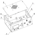
Fig. 1 is the control box structural representation.
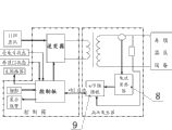
Fig. 2 roof pressure resistant testing device schematic diagram.
Fig. 3 is the theory diagram of inverter.
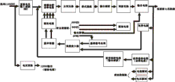
Fig. 4 control panel theory diagram.
Among the figure: 1, cabinet, 2, inverter, 3, control panel, 4, guidance panel, 5, chassis cover, 6, input/output port, 7, display module, 8, current transformer, 9, the A/D change-over panel.
Embodiment
Below in conjunction with accompanying drawing the utility model is made detailed description:
The utility model provides a kind of electric locomotive roof pressure resistant testing device; This device comprises control box, high pressure generator two partly; Control box includes cabinet 1, inverter 2, be the guidance panel 4 of control core plate 3 and cabinet 1 with the single-chip microcomputer, inverter 2, control panel 3 are installed in the cabinet 1, cabinet 1 upper end is provided with chassis cover 5; Have input/output port 6 on cabinet 1 trailing flank; Guidance panel 4 is provided with display module 7, and high pressure generator comprises and be provided with current transformer 8, A/D change-over panel 9 that display module 7 is connected with control panel 3.
Electric locomotive roof pressure resistant testing device is 0~116V with the 110V direct supply through inverter 2 inversions; 0~172V; 0~232V (it is different and different to look vehicle)/50Hz alternating current; High-voltage mutual inductor boosts to 0~29kV with it, contacts with roof high tension voltage electric equipment through controlling testing equipment.Current transformer 8 detects the HT testing transformer high voltage side current, and resistor voltage divider circuit is gathered high side voltage and sent into A/D change-over panel 9 in the lump, the voltage and current value after the conversion is sent into single-chip microcomputer (control panel 3) handle, show.The steward judges the insulating property of roof high-tension apparatus through observing the display screen on the control box.When insulating property were low, device can be reported to the police automatically.Control panel 3 is circumscribed with displaying alarm.When this device is not worked, be in off-state, do not influence locomotive and normally move, improved security with the roof insulator arrangement.Its ultimate principle is as shown in Figure 2.
Because locomotive under the situation that does not rise bow, has only accumulator as power supply, therefore need design stability, reliable inverter power supply device, be 0 variable~116V with dc inverter, 0~172V, the alternating current of 0~232V 50Hz.The design of inverter mainly solves the voltage stability and output waveform (sine wave) problem of inverter.Inverter adopts dedicated PWM controller, high-power V MOS device etc.PWM controller output pulse signal control high frequency bridge; 110V direct current behind voltage regulation filtering is become alternating-current pulse; Again through boosting, rectifying and wave-filtering becomes half-sinusoid, through single-chip microcomputer alternately triggering and output AC voltage two groups of electric power MOSFET of Zhou Boguan.This inverter adopts monolithic processor controlled SPWM control technology.Direct-flow input end adopts advanced anti-filling noise to suppress technology, and the antinoise flowing backward device and the wave filter of the built-in precision of inverter meet electromagnetic compatibility standard, with other communication apparatus common dc screens the time, does not disturb mutually; The PFC rectification circuit that the AC/DC converter using is advanced makes input power factor up to more than 95%; Be provided with safeguard measures such as exchanging overvoltage, overload, short circuit simultaneously, make this inverter have very high stability and reliability.
Display module: the demonstration of the voltage/current that the steward can be through the finder LCD display, confirm the roof high-tension apparatus whether ground connection or insulation reduce, represent normally during greater than setting value less than 3.5A and display voltage if show electric current; If show electric current greater than 3.5A, and display voltage representes that roof high voltage equipment insulation performance reduces or the ground connection place is arranged, and reports to the police simultaneously during less than setting value.
Fig. 1 is the control box synoptic diagram: 1, input voltage: DC110V (77V-137.5V); 2, output voltage: AC 0~232V; 3, frequency: 50 ± 1%Hz; 4, capacity: 1kVA (MAX); 5, waveform: sine wave.High pressure generator: 1, input voltage: AC 0~240V; 2, output voltage: AC 0-29kV; 3, frequency: 50 ± 1%HZ; 4, capacity: 0.6kVA (MAX).
Claims (1)
1. electric locomotive roof pressure resistant testing device; This device comprises control box, high pressure generator two partly; It is characterized in that: control box includes cabinet (1), inverter (2), be the guidance panel (4) of control core plate (3) and cabinet (1) with the single-chip microcomputer, and inverter (2), control panel (3) are installed in the cabinet (1), and cabinet (1) upper end is provided with chassis cover (5); Have input/output port (6) on cabinet (1) trailing flank; Guidance panel (4) is provided with display module (7), and high pressure generator comprises and be provided with current transformer (8), A/D change-over panel (9) that display module (7) is connected with control panel (3).
Priority Applications (1)
| Application Number | Priority Date | Filing Date | Title |
|---|---|---|---|
| CN2011203676817U CN202256586U (en) | 2011-09-29 | 2011-09-29 | Dielectric withstand voltage testing device for roof of electric locomotive |
Applications Claiming Priority (1)
| Application Number | Priority Date | Filing Date | Title |
|---|---|---|---|
| CN2011203676817U CN202256586U (en) | 2011-09-29 | 2011-09-29 | Dielectric withstand voltage testing device for roof of electric locomotive |
Publications (1)
| Publication Number | Publication Date |
|---|---|
| CN202256586U true CN202256586U (en) | 2012-05-30 |
Family
ID=46117805
Family Applications (1)
| Application Number | Title | Priority Date | Filing Date |
|---|---|---|---|
| CN2011203676817U Expired - Lifetime CN202256586U (en) | 2011-09-29 | 2011-09-29 | Dielectric withstand voltage testing device for roof of electric locomotive |
Country Status (1)
| Country | Link |
|---|---|
| CN (1) | CN202256586U (en) |
Cited By (4)
| Publication number | Priority date | Publication date | Assignee | Title |
|---|---|---|---|---|
| CN102866330A (en) * | 2012-09-11 | 2013-01-09 | 株洲中车电力机车配件有限公司 | Locomotive high-low voltage insulation detection device |
| CN104614652A (en) * | 2015-02-09 | 2015-05-13 | 韩社教 | High voltage generator for motor train unit roof |
| CN104849631A (en) * | 2015-05-18 | 2015-08-19 | 湖南工业大学 | Locomotive roof insulation testing system |
| CN106896304A (en) * | 2017-04-18 | 2017-06-27 | 河北中车科技发展有限公司 | Ultralow frequency EMUs roof high-pressure system insulation monitoring and warning device and monitoring method |
-
2011
- 2011-09-29 CN CN2011203676817U patent/CN202256586U/en not_active Expired - Lifetime
Cited By (6)
| Publication number | Priority date | Publication date | Assignee | Title |
|---|---|---|---|---|
| CN102866330A (en) * | 2012-09-11 | 2013-01-09 | 株洲中车电力机车配件有限公司 | Locomotive high-low voltage insulation detection device |
| CN102866330B (en) * | 2012-09-11 | 2015-12-16 | 株洲中车电力机车配件有限公司 | A kind of locomotive high-low voltage insulation detection device |
| CN104614652A (en) * | 2015-02-09 | 2015-05-13 | 韩社教 | High voltage generator for motor train unit roof |
| CN104849631A (en) * | 2015-05-18 | 2015-08-19 | 湖南工业大学 | Locomotive roof insulation testing system |
| CN104849631B (en) * | 2015-05-18 | 2017-10-17 | 湖南工业大学 | A kind of locomotive roof insulation testing system |
| CN106896304A (en) * | 2017-04-18 | 2017-06-27 | 河北中车科技发展有限公司 | Ultralow frequency EMUs roof high-pressure system insulation monitoring and warning device and monitoring method |
Similar Documents
| Publication | Publication Date | Title |
|---|---|---|
| CN104768861B (en) | The method of electrical safety in safety device, elevator device, frequency converter and monitoring elevator device | |
| CN110703138B (en) | Ground fault detection method and device for traction system of motor train unit | |
| CN202256586U (en) | Dielectric withstand voltage testing device for roof of electric locomotive | |
| CN201440161U (en) | Locomotive top insulation detection equipment for locomotive | |
| WO2019114039A1 (en) | Multi-system emu high-voltage power supply system and train | |
| CN203551726U (en) | Electric locomotive roof insulation detecting device | |
| CN109327073A (en) | A kind of double dynamical power supply system | |
| CN104330733A (en) | Train roof insulation detection device | |
| CN101364727B (en) | Overvoltage inhibiting apparatus for traction power-supply system in process of vehicle passing through phase breaking | |
| CN104330718A (en) | Analysis method for train insulation detection | |
| CN203237059U (en) | Static/dynamic online insulation monitoring device for high voltage power supply system of electric locomotive | |
| CN104330717A (en) | Train insulation detection system | |
| CN204228897U (en) | Train Insulation Inspection System | |
| CN203551727U (en) | Electric locomotive roof insulation detector | |
| CN110654273A (en) | Flexible grounding device for controlling steel rail potential | |
| CN2793736Y (en) | Insulating resistance inspector of high-voltage apparatus on top of electric locomotive | |
| CN2541249Y (en) | Power locomotive top high voltage equipment insulation fault detector | |
| CN205356202U (en) | A postponing implementation braking circuit for electronic round of truck | |
| CN204228896U (en) | Train Insulation monitoring control device | |
| CN210283919U (en) | Rail engineering truck with contact net power supply system | |
| CN111186449B (en) | Electric drive system | |
| CN103576077A (en) | Device for detecting three-phase inverter power module | |
| CN208797565U (en) | A kind of overvoltage crowbar for direct current operative power source input | |
| CN103178363A (en) | Grounding device for lightning impulse | |
| CN203519779U (en) | Detection apparatus of three-phase inverter power module |
Legal Events
| Date | Code | Title | Description |
|---|---|---|---|
| C14 | Grant of patent or utility model | ||
| GR01 | Patent grant | ||
| CP03 | Change of name, title or address | ||
| CP03 | Change of name, title or address |
Address after: 610066 Sichuan city of Chengdu province Chengdu economic and Technological Development Zone (Longquanyi District) Ascot Road No. 228 Patentee after: Chengdu Hongyuan Polytron Technologies Inc Address before: 610066 No. 39, West Main Road, Chengdu economic and Technological Development Zone, Sichuan Patentee before: Chengdu Changtong Railway Technology Exploitation Co., Ltd. |
|
| CX01 | Expiry of patent term | ||
| CX01 | Expiry of patent term |
Granted publication date: 20120530 |