CN201771265U - Intelligent door lock inverse locking mechanism - Google Patents
Intelligent door lock inverse locking mechanism Download PDFInfo
- Publication number
- CN201771265U CN201771265U CN2010205286036U CN201020528603U CN201771265U CN 201771265 U CN201771265 U CN 201771265U CN 2010205286036 U CN2010205286036 U CN 2010205286036U CN 201020528603 U CN201020528603 U CN 201020528603U CN 201771265 U CN201771265 U CN 201771265U
- Authority
- CN
- China
- Prior art keywords
- block
- dead bolt
- door lock
- driven gear
- intelligent door
- Prior art date
- Legal status (The legal status is an assumption and is not a legal conclusion. Google has not performed a legal analysis and makes no representation as to the accuracy of the status listed.)
- Expired - Fee Related
Links
Images


Landscapes
- Lock And Its Accessories (AREA)
Abstract
The utility model relates to an intelligent door lock inverse locking mechanism comprising a handle, a driving gear fixedly connected with the handle, a driven gear cooperated with the driving gear, a latch deflector rod protrusion wheel rotating in the single direction with the driven gear through a block component, a camshaft passing through the latch deflector rod protrusion wheel and fixedly connected with the latch deflector rod protrusion wheel , and a lock core mechanism connected with the camshaft and used to drive the latch of the inverse locking to move straightly. In the utility model, the handle can be rotated to drive the driving gear to rotate, and the driving gear can drive the driven gear engaged with the driving gear to rotate. The block component is disposed between the driven gear and the latch deflector rod protrusion wheel, thereby the driven gear can drive the latch deflector rod protrusion wheel to rotate in the single direction and to idle reversely. The camshaft passes through the middle of the latch deflector rod protrusion wheel, and the latch deflector rod protrusion wheel rotates to drive the camshaft to rotate. One end of the camshaft is connected with the lock core mechanism, and the camshaft rotates to drive the latch of the inverse locking to move straightly, thereby the inverse locking can be realized.
Description
Technical field
The utility model relates to a kind of intelligent door lock, more particularly, relates to a kind of mechanism of locking of intelligent door lock.
Background technology
Door lock is a kind of device that ensures indoor security, and at present, intelligent door lock is provided with mostly locks mechanism, yet this mechanism of locking is the indoor mechanism of locking, to be personnel lock button in indoor turn realizes locking, even outdoor personnel have key, in the inlet chamber of can not unblanking; Knob is locked in the indoor occupant turn, and after cancellation was locked, outdoor personnel can normally unblank in the inlet chamber.
Indoor defective of locking existence is that safety is not enough, this class locks that mechanism ensures be personnel in indoor safety in this case, in case indoor owner goes out, the safety in house just can not get ensureing.
The utility model content
The technical problems to be solved in the utility model is, all is that the indoor mechanism of locking is set at intelligent door lock in the prior art, can not carry out outdoor this defective of locking, and provides a kind of intelligent door lock to lock mechanism and can realize locking outdoors.
The technical scheme that its technical problem that solves the utility model adopts is: a kind of intelligent door lock is locked mechanism, it is characterized in that, comprise handle, with the affixed driving gear of described handle, with the driven gear of described driving gear engagement fit, with the dead bolt driving lever cam of described driven gear by block assembly one-directional rotation, run through described dead bolt driving lever cam and be connected and drive and lock the straight-line lock core of dead bolt mechanism with the affixed camshaft of described dead bolt driving lever cam and with described camshaft.
A kind of intelligent door lock of the utility model is locked mechanism, and is preferred, and described block assembly comprises the groove that is arranged on the block on the described dead bolt driving lever cam and is arranged on the described block motion of confession on the described driven gear.
A kind of intelligent door lock of the utility model is locked mechanism, and preferred, described groove comprises a block face that cooperates with described block.
A kind of intelligent door lock of the utility model is locked mechanism, and is preferred, and described block assembly comprises the groove that is arranged on the block on the described driven gear and is arranged on the described block motion of confession on the described dead bolt driving lever cam.
A kind of intelligent door lock of the utility model is locked mechanism, and preferred, described groove comprises a block face that cooperates with described block.
A kind of intelligent door lock of the utility model is locked mechanism, and is preferred, and described block assembly comprises and is arranged on first block on the described driven gear and is arranged on second block on the described dead bolt driving lever cam; Described first block contacts with the described second block face.
A kind of intelligent door lock of the utility model is locked mechanism, and is preferred, also comprises the handle back-moving spring that is connected with described handle.
The utility model can reach following beneficial effect: rotary handle drives driving gear and rotates, driving gear drives the driven gear that is engaged with cooperation and rotates, by between driven gear and dead bolt driving lever cam, the block assembly being set, realize that driven gear drives dead bolt driving lever cam one-directional rotation and oppositely idle running; Run through being provided with camshaft in the middle part of the dead bolt driving lever cam, thereby dead bolt driving lever cam rotation drives the rotation of camshaft; Camshaft one end is connected with lock core mechanism, and the in-house dead bolt rectilinear motion of locking of lock core is stirred in the rotation of camshaft, thereby realizes locking.
Description of drawings
The utility model is described in further detail below in conjunction with drawings and Examples, in the accompanying drawing:
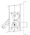
Fig. 1 is that the master that a kind of intelligent door lock of the present utility model is locked mechanism looks schematic diagram;
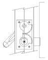
Fig. 2 is the A-A cross-sectional schematic that a kind of intelligent door lock of the present utility model is locked Fig. 1 of mechanism;
Fig. 3 is the position view before of the present utility model kind of intelligent door lock locked locking of mechanism;
Fig. 4 is the position view in the process locked that of the present utility model kind of intelligent door lock locked mechanism;
Fig. 5 is the position view that back handle resets of locking that of the present utility model kind of intelligent door lock locked mechanism;
Fig. 6 is that of the present utility model kind of intelligent door lock locked the position view that locking of mechanism lifted under the back handle;
Fig. 7 is the position view of of the present utility model kind of intelligent door lock when locking unblanking of mechanism;
Fig. 8 is the schematic rear view that a kind of intelligent door lock of the present utility model is locked mechanism;
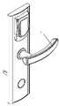
Fig. 9 is that a kind of intelligent door lock of the present utility model is locked the schematic perspective view of mechanism.
The specific embodiment
Understand for technical characterictic of the present utility model, purpose and effect being had more clearly, now contrast accompanying drawing and describe the specific embodiment of the present utility model in detail.
Lock the preferred embodiment that mechanism provides as Fig. 1, Fig. 2, Fig. 8 and Fig. 9 for a kind of intelligent door lock of the utility model, comprise handle 1, with the affixed driving gear 2 of handle 1, with the driven gear 3 of driving gear 2 engagement fit, with the dead bolt driving lever cam 4 of driven gear 3 by block assembly one-directional rotation, run through dead bolt driving lever cam 4 and be connected with the affixed camshaft 9 of dead bolt driving lever cam 4 and with camshaft 9 and drive and lock the straight-line lock core of dead bolt 6 mechanism.
By being set, the block assembly realizes the unidirectional motion of dead bolt driving lever cam 4 between dead bolt driving lever cam 4 and the driven gear 3.
The embodiment one of block assembly, as shown in Figure 1, driven gear 3 is provided with groove 10, and dead bolt driving lever cam 4 is provided with the block 11 of projection, and the block face that cooperatively interacts between block 11 and the groove 10 promotes block 11 by block face and moves in groove 10.Sky revolves lock core under the situation of normally unblanking, and handle is turn along clockwise direction, so the circumferential lengths of groove 10 has certain limitation, and preferred, dead bolt driving lever cam 4 is rotated counterclockwise 40 ° along groove.When driven gear 3 is rotated counterclockwise, drives dead bolt driving lever cam 4 and be rotated counterclockwise simultaneously; Otherwise when driven gear 3 turned clockwise, then dead bolt driving lever cam 4 rested on the original position, and promptly driven gear 3 dallies clockwise, thereby realized the one-directional rotation of dead bolt driving lever cam 4.
The embodiment two of block assembly, dead bolt driving lever cam 4 is provided with groove 10, and driven gear 3 is provided with the block 11 of projection, and the block face that cooperatively interacts between block 11 and the groove 10 promotes block 11 by block face and moves in groove 10.Sky revolves lock core under the situation of normally unblanking, and handle is turn along clockwise direction, so the circumferential lengths of groove 10 has certain limitation, and preferred, dead bolt driving lever cam 4 is rotated counterclockwise 40 ° along groove.When driven gear 3 is rotated counterclockwise, drives dead bolt driving lever cam 4 and be rotated counterclockwise simultaneously; Otherwise when driven gear 3 turned clockwise, then dead bolt driving lever cam 4 rested on the original position, and promptly driven gear 3 dallies clockwise, thereby realized the one-directional rotation of dead bolt driving lever cam 4.
The embodiment three of block assembly, dead bolt driving lever cam 4 are provided with first block of projection, and driven gear 3 is provided with second block of projection, and the block face that cooperatively interacts between first block and second block promotes the motion of first block by block face second block.Sky revolves lock core under the situation of normally unblanking, and handle is turn along clockwise direction, so the circumferential lengths of groove 10 has certain limitation, and preferred, dead bolt driving lever cam 4 is rotated counterclockwise 40 ° along groove.When driven gear 3 is rotated counterclockwise, drives dead bolt driving lever cam 4 and be rotated counterclockwise simultaneously; Otherwise when driven gear 3 turned clockwise, then dead bolt driving lever cam 4 rested on the original position, and promptly driven gear 3 dallies clockwise, thereby realized the one-directional rotation of dead bolt driving lever cam 4.
Further, camshaft 9 runs through dead bolt driving lever cam 4, and both are integrally welded, when dead bolt driving lever cam 4 is rotated counterclockwise, can drives camshaft 9 and be rotated counterclockwise.
Camshaft 9 is connected with lock core mechanism, and the in-house dead bolt 6 of locking of the rotating drive lock core of camshaft 9 is done rectilinear motion, locks dead bolt 6 and stretches out and insert in the door back gauge 8, promptly locks dead bolt 6 and finishes and lock.
The in-house dead bolt 6 of locking of the rotating drive lock core of camshaft 9 moves, and camshaft 9 is that screw mandrel drives with the connected mode of locking dead bolt 6.
Further, but handle reduction torsion spring 5 bi-directional drive handles 1 reset.Driving gear 2, driven gear 3 and dead bolt driving lever cam 4 are by gear train cover plate 7 fixed gear planes, limiting gear axial float.
The explanation of operating principle schematic diagram component: 0 ° is horizontal direction, promptly empty handle residing normality position under reset case of revolving lock core.
As shown in Figure 3, after door is shut, the original state when also not locked.Handle 1 is in 0 ° of position, and other each parts also all are in 0 ° original state.
As shown in Figure 4, when locking, handle 1 upwards lifts, handle 1 drives driving gear 2 and clockwise rotates, 40 ° of design corners, driving gear 2 drive driven gear 3 inhours and rotate 40 °, and driven pulley drives dead bolt driving lever cam 4 simultaneously and also rotates 40 ° together, camshaft 9 promotes lock core mechanism and makes that locking dead bolt 6 stretches out, and reaches and locks purpose.
As shown in Figure 5, release handle 1 is got back to 0 ° of position at the drive lower handle 1 of reduction torsion spring 5, and driving gear 2 and driven gear 3 are also all got back to 0 ° of position.Yet dead bolt driving lever cam 4 guarantees that but because the restriction of lock core mechanism rests on and locks the position locking dead bolt 6 is not withdrawn by gear movement.
As shown in Figure 6, after door is locked, under the situation that does not have legal key or electronics badge, someone is downward from the outside, i.e. normal door direction turning handle 1, at this moment, gear train idle running can not influence and lock dead bolt 6 and dead bolt driving lever camshaft 4 and remain on and lock on the position.
As shown in Figure 7, when using legal badge or key to open the door, the corresponding mechanism action in the lock core has constituted the condition of opening the door.Turning handle 1 under the clockwise direction, and the driving lever of handle 1 drives the mechanism action in the lock core, locks dead bolt 6 withdrawals, opens door lock.The gear train of this moment still is idle running, locks resetting of dead bolt 6 and dead bolt driving lever cam 4 and is that mechanism by lock core inside drives, and is not still driven by gear train.
This mechanism is simple and practical, makes full use of " residue " function that sky revolves lock core, the purpose that the handle of having realized raising one's hand is locked outdoors, and simple, practicality and cost are low.This " sky revolves lock core " is very universal, and be cheap and be easy to obtain.The door lock of this mechanism is transformed the safety that original door lock is not only cheap, convenient but also can improve door lock widely.
In conjunction with the accompanying drawings embodiment of the present utility model is described above; but the utility model is not limited to the above-mentioned specific embodiment; the above-mentioned specific embodiment only is schematic; rather than it is restrictive; those of ordinary skill in the art is under enlightenment of the present utility model; not breaking away under the scope situation that the utility model aim and claim protect, also can make a lot of forms, these all belong within the protection of the present utility model.
Claims (7)
1. an intelligent door lock is locked mechanism, it is characterized in that, comprise handle (1), with the affixed driving gear (2) of described handle (1), with the driven gear (3) of described driving gear (2) engagement fit, with the dead bolt driving lever cam (4) of described driven gear (3) by block assembly one-directional rotation, run through described dead bolt driving lever cam (4) and be connected and drive and lock the straight-line lock core of dead bolt (6) mechanism with the affixed camshaft (9) of described dead bolt driving lever cam (4) and with described camshaft (9).
2. intelligent door lock according to claim 1 is locked mechanism, it is characterized in that described block assembly comprises the block (11) that is arranged on the described dead bolt driving lever cam (4) and is arranged on described driven gear (3) goes up the groove (10) that moves for described block (11).
3. intelligent door lock according to claim 2 is locked mechanism, it is characterized in that, described groove (10) comprises a block face that cooperates with described block (11).
4. intelligent door lock according to claim 1 is locked mechanism, it is characterized in that, described block assembly comprises being arranged on the block on the described driven gear (3) and being arranged on described dead bolt driving lever cam (4) goes up the groove that moves for described block.
5. intelligent door lock according to claim 4 is locked mechanism, it is characterized in that, described groove (10) comprises a block face that cooperates with described block (11).
6. intelligent door lock according to claim 1 is locked mechanism, it is characterized in that, described block assembly comprises and is arranged on first block on the described driven gear (3) and is arranged on second block on the described dead bolt driving lever cam (4); Described first block contacts with the described second block face.
7. intelligent door lock according to claim 1 is locked mechanism, it is characterized in that, also comprises the handle back-moving spring (5) that is connected with described handle (1).
Priority Applications (1)
| Application Number | Priority Date | Filing Date | Title |
|---|---|---|---|
| CN2010205286036U CN201771265U (en) | 2010-09-14 | 2010-09-14 | Intelligent door lock inverse locking mechanism |
Applications Claiming Priority (1)
| Application Number | Priority Date | Filing Date | Title |
|---|---|---|---|
| CN2010205286036U CN201771265U (en) | 2010-09-14 | 2010-09-14 | Intelligent door lock inverse locking mechanism |
Publications (1)
| Publication Number | Publication Date |
|---|---|
| CN201771265U true CN201771265U (en) | 2011-03-23 |
Family
ID=43751109
Family Applications (1)
| Application Number | Title | Priority Date | Filing Date |
|---|---|---|---|
| CN2010205286036U Expired - Fee Related CN201771265U (en) | 2010-09-14 | 2010-09-14 | Intelligent door lock inverse locking mechanism |
Country Status (1)
| Country | Link |
|---|---|
| CN (1) | CN201771265U (en) |
Cited By (5)
| Publication number | Priority date | Publication date | Assignee | Title |
|---|---|---|---|---|
| CN104631912A (en) * | 2015-02-11 | 2015-05-20 | 浙江钟铮锁业有限公司 | Mechanical and electronic combined control lock |
| WO2018040152A1 (en) * | 2016-08-31 | 2018-03-08 | 李双杰 | Door lock panel apparatus |
| CN109736639A (en) * | 2019-01-25 | 2019-05-10 | 广东金点原子安防科技股份有限公司 | A kind of transmission mechanism of lock tongue |
| CN110439365A (en) * | 2019-09-09 | 2019-11-12 | 温州安华实业有限公司 | A kind of handle-door lock locked |
| CN113700399A (en) * | 2018-12-19 | 2021-11-26 | 麦格纳覆盖件有限公司 | Actuator and door actuating system for a door of a vehicle |
-
2010
- 2010-09-14 CN CN2010205286036U patent/CN201771265U/en not_active Expired - Fee Related
Cited By (6)
| Publication number | Priority date | Publication date | Assignee | Title |
|---|---|---|---|---|
| CN104631912A (en) * | 2015-02-11 | 2015-05-20 | 浙江钟铮锁业有限公司 | Mechanical and electronic combined control lock |
| WO2018040152A1 (en) * | 2016-08-31 | 2018-03-08 | 李双杰 | Door lock panel apparatus |
| CN113700399A (en) * | 2018-12-19 | 2021-11-26 | 麦格纳覆盖件有限公司 | Actuator and door actuating system for a door of a vehicle |
| CN109736639A (en) * | 2019-01-25 | 2019-05-10 | 广东金点原子安防科技股份有限公司 | A kind of transmission mechanism of lock tongue |
| CN110439365A (en) * | 2019-09-09 | 2019-11-12 | 温州安华实业有限公司 | A kind of handle-door lock locked |
| CN110439365B (en) * | 2019-09-09 | 2024-05-28 | 温州安华实业有限公司 | Handle door lock capable of being locked reversely |
Similar Documents
| Publication | Publication Date | Title |
|---|---|---|
| CN201771265U (en) | Intelligent door lock inverse locking mechanism | |
| CN106320815B (en) | A kind of intelligent panel lock | |
| CN203420535U (en) | Intelligent TM (touch memory) card lock | |
| CN201661141U (en) | Interpolant electric door lock | |
| CN202064694U (en) | Intelligent antitheft lock capable of automatically locking | |
| CN201214944Y (en) | Auto-locking sliding window | |
| CN202152569U (en) | Novel door lock | |
| CN201627410U (en) | Intelligent lock with improved structure | |
| CN201843413U (en) | Three-way locking device and electric-controlled semi-automatic lock of three-way locking bolt operated in electric-controlled way | |
| CN102226360A (en) | Axially driven clutch type electronic door lock clutch | |
| CN207212095U (en) | A kind of inner swing door drive device | |
| CN202689691U (en) | Door lock | |
| CN214943204U (en) | Door lock | |
| CN110847712B (en) | Intelligent door lock | |
| CN208267557U (en) | A kind of Fingerprint Lock | |
| CN203201300U (en) | Prying-resistant structure of mortise lock | |
| CN201007131Y (en) | Improved electronic lock | |
| CN211008040U (en) | Auxiliary lock tongue mechanism | |
| CN208251854U (en) | A kind of door lock | |
| CN209799610U (en) | Electronic lock | |
| CN208441645U (en) | A kind of full-automatic motor driving lock body structure | |
| CN102071839B (en) | Motor lock | |
| CN203081082U (en) | Theftproof lock with two annular spring bolt | |
| CN202324893U (en) | Automatic mortise lock | |
| CN201581714U (en) | Mechanical-electrical integration-type remote anti-theft lock |
Legal Events
| Date | Code | Title | Description |
|---|---|---|---|
| C14 | Grant of patent or utility model | ||
| GR01 | Patent grant | ||
| C17 | Cessation of patent right | ||
| CF01 | Termination of patent right due to non-payment of annual fee |
Granted publication date: 20110323 Termination date: 20130914 |