CN201629187U - Lightning prevention insulator of power transmission lines - Google Patents
Lightning prevention insulator of power transmission lines Download PDFInfo
- Publication number
- CN201629187U CN201629187U CN2010201524637U CN201020152463U CN201629187U CN 201629187 U CN201629187 U CN 201629187U CN 2010201524637 U CN2010201524637 U CN 2010201524637U CN 201020152463 U CN201020152463 U CN 201020152463U CN 201629187 U CN201629187 U CN 201629187U
- Authority
- CN
- China
- Prior art keywords
- insulator
- power transmission
- transmission lines
- lightning prevention
- lightning
- Prior art date
- Legal status (The legal status is an assumption and is not a legal conclusion. Google has not performed a legal analysis and makes no representation as to the accuracy of the status listed.)
- Expired - Fee Related
Links
Images

Landscapes
- Insulators (AREA)
Abstract
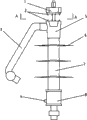
The utility model discloses a lightning prevention insulator of power transmission lines which relates to an insulator used in power transmission lines, in particular to an insulator with lightning prevention function. An insulating mandril 9 is arranged in the middle; an insulating umbrella sleeve 7 is arranged in the outer layer; and armour clamps are arranged at the two ends. The armour clamp 5 at the upper end is connected with a connecting terminal 1 and a starting rod 3; the armour clamp 8 at the lower end is an adapting end; and a discharge salient 4 is arranged on the armour clamp 8 at the lower which is of the same side to the starting rod. The lightning prevention insulator of power transmission lines has the structural characteristics of insulators and can be suitable for high-tension overhead power lines to play the roles of insulating and supporting conductors; moreover, the lightning prevention insulator of power transmission lines also has the characteristics of arrester and can play the protective effects of preventing broken lines caused by lightning.
Description
Technical field
The utility model relates to the insulator that uses in a kind of power transmission line, particularly belongs to a kind of insulator with lightning protection function.
Background technology
The existing major measure of suspended insulated guide wire lightning-caused breaking that prevents has: set up overhead ground wire; Zinc oxide arrester is installed, in parallel with insulator or connect; Metal hoop is installed, load side dress arc-preventing metal utensil on pillar insulator.Existing lightning protection measures exists that cost of investment is big, the complicated drawback of construction and installation.
Existing insulator generally adopts insulation mandrel to wrap up in the insulation umbrella cover outward, the version that connects gold utensil is established at two ends, and the end gold utensil needs the strip off wire insulation when being connected with lead, causes core water inlet and corrosion.In addition, the umbrella leaf size of insulation umbrella cover is consistent, and spacing is even, when raining, very easily forms the series connection water droplet at the edge of umbrella leaf, and circuit connects electricity thereby cause up and down, causes circuit burn even bigger circuit accident.
Summary of the invention
The purpose of this utility model promptly is to provide a kind of novel transmission line anti-thunder insulator, to reach the insulator effect of existing insulation and support wire, can prevent the defencive function of lightning-caused breaking again, and convenient, the safe and reliable purpose of installation.
Transmission line anti-thunder insulator disclosed in the utility model, the centre is an insulation mandrel, and outer is the insulation umbrella cover, and two ends are gold utensil, it is characterized in that, and the upper end gold utensil connects terminals and starting rod; The lower end gold utensil is a socket end, and the homonymy with starting rod on it has the discharge projection.
Transmission line anti-thunder insulator disclosed in the utility model has the architectural feature of insulator, applicable to the high voltage overhead power circuit, plays the effect of insulation and support wire, has the feature of lightning arrester again, can play the protection effect that prevents lightning-caused breaking.
Description of drawings
Accompanying drawing partly discloses specific embodiment of the utility model, wherein:
Fig. 1, the utility model structural representation;
Fig. 2, the utility model section of structure;
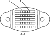
Fig. 3, the A-A of Fig. 1 is to view.
Embodiment
As shown in Figure 1 and Figure 2, transmission line anti-thunder insulator disclosed in the utility model, the centre is an insulation mandrel 9, can adopt the epoxy resin rod, and outer have umbrella leaf 6 for insulation umbrella cover 7 on it, all make with silastic material, and two ends are gold utensil, are aluminium matter or copper.Upper end gold utensil 5 connects terminals 1 and starting rod 3, can be processed as one during making.Terminals have compound puncture needle 2, and the insulating barrier of penetrable lead is realized energising, has installation characteristics easily.Compound puncture needle 2 can be and terminals end cap consubstantiality, homogeneity, also can be differing texture, and becomes one by welding, casting.
Lower end gold utensil 8 is a socket end, at the homonymy with starting rod discharge projection 4 is arranged.Described discharge projection 4 is installed on the gold utensil of lower end by the bolt mode, can regulate the spacing of itself and starting rod discharge head by rotation.
Characteristics of the present utility model also are, on above-mentioned insulation umbrella cover 7, middle umbrella leaf diameter is less than the adjacent umbrella leaf diameter in its both sides, this structure can avoid forming the series connection water droplet between last subumbrella leaf when misty rain weather, prevent the insulator circuit company electricity at two ends up and down, can prevent that also filthy water and birds droppings etc. from causing the generation of pollution flashover accident.
Claims (4)
1. transmission line anti-thunder insulator, the centre is insulation mandrel (9), outerly is insulation umbrella cover (7), and two ends are gold utensil, it is characterized in that, and upper end gold utensil (5) connects terminals (1) and starting rod (3); Lower end gold utensil (8) is a socket end, and the homonymy with starting rod on it has discharge projection (4).
2. transmission line anti-thunder insulator according to claim 1, its feature are that also described terminals (1) have compound puncture needle (2).
3. transmission line anti-thunder insulator according to claim 2, its feature are that also described discharge projection (4) is installed on the gold utensil of lower end by the bolt mode.
4. transmission line anti-thunder insulator according to claim 3, its feature are that also on the described insulation umbrella cover (7), middle umbrella leaf diameter is less than the adjacent umbrella leaf diameter in its both sides.
Priority Applications (1)
| Application Number | Priority Date | Filing Date | Title |
|---|---|---|---|
| CN2010201524637U CN201629187U (en) | 2010-04-02 | 2010-04-02 | Lightning prevention insulator of power transmission lines |
Applications Claiming Priority (1)
| Application Number | Priority Date | Filing Date | Title |
|---|---|---|---|
| CN2010201524637U CN201629187U (en) | 2010-04-02 | 2010-04-02 | Lightning prevention insulator of power transmission lines |
Publications (1)
| Publication Number | Publication Date |
|---|---|
| CN201629187U true CN201629187U (en) | 2010-11-10 |
Family
ID=43060586
Family Applications (1)
| Application Number | Title | Priority Date | Filing Date |
|---|---|---|---|
| CN2010201524637U Expired - Fee Related CN201629187U (en) | 2010-04-02 | 2010-04-02 | Lightning prevention insulator of power transmission lines |
Country Status (1)
| Country | Link |
|---|---|
| CN (1) | CN201629187U (en) |
Cited By (2)
| Publication number | Priority date | Publication date | Assignee | Title |
|---|---|---|---|---|
| CN102024543A (en) * | 2010-12-28 | 2011-04-20 | 大连法伏安电器有限公司 | Composite insulator support fixing gap line type arrester |
| CN104299730A (en) * | 2014-10-30 | 2015-01-21 | 国家电网公司 | Anticorona flange for extra-high voltage post insulator |
-
2010
- 2010-04-02 CN CN2010201524637U patent/CN201629187U/en not_active Expired - Fee Related
Cited By (4)
| Publication number | Priority date | Publication date | Assignee | Title |
|---|---|---|---|---|
| CN102024543A (en) * | 2010-12-28 | 2011-04-20 | 大连法伏安电器有限公司 | Composite insulator support fixing gap line type arrester |
| CN102024543B (en) * | 2010-12-28 | 2016-01-13 | 大连法伏安电器有限公司 | Composite insulator support fixing gap line type arrester |
| CN104299730A (en) * | 2014-10-30 | 2015-01-21 | 国家电网公司 | Anticorona flange for extra-high voltage post insulator |
| CN104299730B (en) * | 2014-10-30 | 2017-12-05 | 国家电网公司 | A kind of anticorona flange for ultra-high-voltage post insulator |
Similar Documents
| Publication | Publication Date | Title |
|---|---|---|
| CN201466635U (en) | Insulating tower head of composite insulating pole tower | |
| CN101325104B (en) | Lightning protection post insulator | |
| CN203386547U (en) | Integrated fixed external series gap self-disengaging metal oxide lightning arrester insulators | |
| CN104952562A (en) | Anti-thunder and anti-icing pin type composite insulator for 10kV power transmission line | |
| CN102157253A (en) | Outer-gap lightning arrester | |
| CN203278165U (en) | 10kV overhead distribution line arrester arrangement structure | |
| CN201435277Y (en) | lightning-proof insulator | |
| CN201170978Y (en) | Lightning protection post column insulator | |
| CN101699573A (en) | Lightning arrester insulator for overhead wire insulated conductor | |
| CN201629187U (en) | Lightning prevention insulator of power transmission lines | |
| CN105788775A (en) | Needle type composite insulator for 10 kV transmission line | |
| CN102938278B (en) | A kind of anti-thunder insulator for 10KV insulated conductor | |
| CN206649951U (en) | A kind of indicating fault lightning protection device | |
| CN204760146U (en) | Anti -icing suspension type composite insulator of lightning protection for 10kV transmission line | |
| CN203150325U (en) | Lightning-protection post insulator | |
| CN202102814U (en) | Porcelain insulator for preventing insulated conductor breakage caused by lightning stroke | |
| CN204732237U (en) | For the lightning-protection ice needle type composite insulator of 10kV transmission line | |
| CN202197102U (en) | Overvoltage protector for circuit fixing gap | |
| CN105139974A (en) | Lightning protection insulator | |
| CN205862897U (en) | A kind of 10kV Multifunctional disaster prevention evil insulator | |
| CN103971865A (en) | Discharge gap cross-arm insulator | |
| CN204517391U (en) | A kind of faulty indication protector | |
| CN204496992U (en) | A kind of insulator supports fixed interval (FI) overvoltage protection device | |
| CN203166445U (en) | Device using coupling ground line to reduce lightning trip-out rate of transmission line | |
| CN201812601U (en) | Lightning protection strut composite insulator |
Legal Events
| Date | Code | Title | Description |
|---|---|---|---|
| C14 | Grant of patent or utility model | ||
| GR01 | Patent grant | ||
| CF01 | Termination of patent right due to non-payment of annual fee | ||
| CF01 | Termination of patent right due to non-payment of annual fee |
Granted publication date: 20101110 Termination date: 20170402 |