CN201380964Y - Multi-rotary-wing leg-wheel type multifunctional aerial robot - Google Patents
Multi-rotary-wing leg-wheel type multifunctional aerial robot Download PDFInfo
- Publication number
- CN201380964Y CN201380964Y CN200920105770U CN200920105770U CN201380964Y CN 201380964 Y CN201380964 Y CN 201380964Y CN 200920105770 U CN200920105770 U CN 200920105770U CN 200920105770 U CN200920105770 U CN 200920105770U CN 201380964 Y CN201380964 Y CN 201380964Y
- Authority
- CN
- China
- Prior art keywords
- rotor
- wall
- robot
- strut bar
- climb
- Prior art date
- Legal status (The legal status is an assumption and is not a legal conclusion. Google has not performed a legal analysis and makes no representation as to the accuracy of the status listed.)
- Expired - Fee Related
Links
Images

Landscapes
- Manipulator (AREA)
Abstract
The utility model discloses a multi-rotary-wing leg-wheel type multifunctional aerial robot, which comprises rotary wings, rotary wing driving motors, wall-climbing upper legs, wall-climbing lower legs, hip joint driving motors, knee joint driving motors, a rigidity reinforcing ring, a robot body, wall walking wheels, landing supporting rods and rotary wing supporting rods. The robot body is a circular disc structure, and four rotary wing supporting rods are symmetrically distributed along the lower surface of the robot body circumferentially. The rotary wing driving motors are fixed at outer ends of the rotary wing supporting rods via screws, and rotary wings are sequentially fixed onto rotating shafts of the rotary wing driving motors. The landing supporting rods are fixedly connected below the rotary wing supporting rods. The rigidity reinforcing ring is fastened above the rotary wing supporting rods. The robot which combines a rotary wing aircraft with a leg-wheel moving mechanism is simple in mechanical structure and easy to be implemented, has high stability and small volume during a flying process, and has high adaptability, high obstacle clearance capacity, wide applicable range and the like during wall climbing.
Description
Technical field
The utility model relates to a kind of aerial robot, is specifically related to the aerial robot of a kind of multi-rotor wheel-leg type multifunctional.
Background technology
At present, many applications all require aircraft can carry out the flight of low-altitude low-speed, hang down idle job, and good manoevreability and disguise are arranged.Therefore, having occurred with the single-rotor helicopter is the flat-bed aerocraft system.This single rotor craft can be realized low-altitude low-speed flight, also can finish certain low idle job, but, owing to adopt a rotor, so the size of rotor is generally all bigger, relatively more dangerous during work, and single rotor aerofoil angle of attack control mechanism complexity, and be single failpoint, so the fault content is relatively poor.And multi-rotor aerocraft has good flight maneuver and stability, can finish the low idle job of many complexity, have vertical takeoff and landing (VTOL) simple, hover and quicken flexibly, characteristics such as strong, the aerial posture adjustment ability of maneuvering performance is strong, realize bigger thrust-weight ratio with respect to single rotor craft at identical operating space Nei Gengyi, increase the proportion of mission payload in overall load.
Be in the aerial robot field's of flat-bed the research with the aircraft, aerial robot is confined to the mono-task mostly, has limited its field of application.It is a development tendency of aerial robot that the task of robot is developed to the multifunction direction by simplification.To fly and climb the wall function and be integrated in one, designing the multi-functional aerial robot that has flight concurrently and climb the wall function is the current problem that needs solution.
Summary of the invention
The purpose of this utility model is the multi-functional aerial robot that to have flight concurrently and climb the wall function in order to realize, adopts to comprise the aerial robot architecture that leg wheel type is climbed wall construction based on many rotors flying platform, proposes the aerial robot of a kind of multi-rotor wheel-leg type multifunctional.
The aerial robot of a kind of multi-rotor wheel-leg type multifunctional of the present utility model comprises rotor, rotor drive motor, climbs the wall thigh, climbs the wall shank, hip joint drive motor, knee joint drive motor, rigidity ring stiffener, robot body, wall road wheel, lands strut bar, rotor strut bar.
The robot body is the circular discoid structure, and four rotor strut bars are symmetrical distribution around robot body's lower surface, and are screwed on the robot body.The rotor drive motor is screwed in the outer end of rotor strut bar, and rotor is fixed on the turning cylinder of rotor drive motor successively.And the plane of rotation of rotor is positioned at the below of rotor strut bar.The strut bar that lands is fixedly connected on rotor strut bar below.Land mounting spring on the strut bar, when robot lands, play and support and the buffering effect.The rigidity ring stiffener is concentric with the robot body, is anchored on the top of rotor strut bar.
Climb the wall thigh and be connected with robot body's upper surface by hip joint, climb the wall shank by knee joint with climb the wall thigh and be connected, climb the wall thigh and climb the symmetrical plane that the wall shank is positioned at robot for two groups.The wall road wheel is positioned at the end of climbing the wall shank.
On hip joint and knee joint, be fixed with hip joint drive motor, knee joint drive motor respectively.
For improving the safety of robot, can a protective device-fender bracket be installed in the periphery of robot.Fender bracket is welded to form by four U-iron silks and an annulus iron wire, and an end of U-iron silk and the strut bar that lands of robot fix, other end welding annulus iron wire, and the height of U-iron silk arrives plane, rotor place.
The aerofoil profile of described rotor adopts the CLARK-Y aerofoil profile.Described rotor strut bar profile cross-sectional plane is set to circle.Spacing is greater than the twice of rotor 1 diameter between each rotor 1 of described robot, and described spacing is the distance of the centre of gration of rotor.
Advantage of the present utility model is:
(1) the utility model is the multi-functional aerial robots of a kind of later-model many rotors, has realized the fusion of rotary wind type aircraft and leg wheel type kinematic mechanism;
(2) physical construction of robot simple, be easy to realize;
(3) robot has advantages such as stability is high, volume is little awing;
(4) robot has advantages such as the wall comformability is strong, obstacle climbing ability is strong, applied widely in climbing wall.
Description of drawings
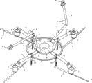
Fig. 1 is the aerial robot construction scheme drawing of a kind of multi-rotor wheel-leg type multifunctional of the utility model;
Fig. 2 is the structural representation after the aerial robot of a kind of multi-rotor wheel-leg type multifunctional of the utility model adds fender bracket;
Among the figure:
1-rotor 2-rotor drive motor 3-climbs wall thigh 4-and climbs the wall shank
5-hip joint drive motor 6-knee joint drive motor 7-rigidity ring stiffener 8-robot body
9-wall road wheel 10-lands strut bar 11-rotor strut bar 12-fender bracket
13-U shape iron wire 14-annulus iron wire
The specific embodiment
The utility model is described in further detail below in conjunction with accompanying drawing.
The utility model is the aerial robot of a kind of multi-rotor wheel-leg type multifunctional, as shown in Figure 1, comprise rotor 1, rotor drive motor 2, climb wall thigh 3, climb wall shank 4, hip joint drive motor 5, knee joint drive motor 6, rigidity ring stiffener 7, robot body 8, wall road wheel 9, land strut bar 10, rotor strut bar 11.
As shown in Figure 1, robot body 8 is the circular discoid structure, and four rotor strut bars 11 are symmetrical distribution around robot body 8 lower surface, and are screwed on robot body 8.Rotor drive motor 2 is screwed in the outer end of rotor strut bar 11, and rotor 1 is fixed on the turning cylinder of rotor drive motor 2 successively, and its rotary power is provided by rotor drive motor 2.And the plane of rotation of rotor 1 is positioned at the below of rotor strut bar 11.The strut bar 11 that lands is fixedly connected on rotor strut bar 8 belows.Land and spring has been installed on the strut bar 11, when robot lands, play and support and the buffering effect.Rigidity ring stiffener 7 is concentric with robot body 8, is anchored on the top of rotor strut bar 11, is used to strengthen the rigidity of rotor strut bar 11.
Climb wall thigh 3 and be connected with robot body's 8 upper surfaces by hip joint, climb wall shank 4 by knee joint with climb wall thigh 3 and be connected, climb wall thigh 3 and climb the symmetrical plane that wall shank 4 is positioned at robot for two groups.Wall road wheel 9 is positioned at the end of climbing wall shank 4.Wall road wheel 9 is the passive type road wheel, no motor-driven.
On hip joint and knee joint, be fixed with hip joint drive motor 5, knee joint drive motor 6 respectively.Describedly climb hip joint between wall thigh 4 and the robot body 8, climb wall thigh 4 and climb knee joint between the wall shank 3, rotational angle is by hip joint drive motor 5, knee joint drive motor 6.Power plant and airborne sensor system place on the robot body 8, by can the attitude angle of accuracy control robot body 8 in flight course to jointly controlling of four rotors 1, and realize that climbing the wall function provides the failure-free guarantee for robot.
For improving the safety of robot, can a protective device-fender bracket 12 be installed in the periphery of robot.As shown in Figure 2; fender bracket 12 is welded to form by four U-iron silks 13 and an annulus iron wire 14; when fender bracket 12 is installed; the spring of strut bar 10 of will landing removes; then U-iron silk 13 1 ends of fender bracket 12 and the strut bar 10 that lands of robot are fixed; other end welding annulus iron wire 14, the height of U-iron silk 13 arrives plane, rotor 1 place.The protective device that increases can effectively be avoided people and the thing of the rotor 1 of robot around damaging in flight course, also can avoid robot climbing under the wall state interference that bumps of rotor 1 and wall simultaneously.Be to increase the practicality of robot, can also climb on the wall shank 4 two of robot increases apparatus for work, as clamper etc., makes robot can carry out operations such as simple clamping operation at the object on the wall in climbing the wall process.
For improving in-flight aeroperformance of the aerial robot of a kind of multi-rotor wheel-leg type multifunctional of the present utility model and whole thrust-weight ratio, the aerofoil profile of described rotor 1 adopts the CLARK-Y aerofoil profile.Its feature is under power unmodified situation, has adopted wide blade again, and the design of little blade angle makes robot reach maximum thrust under certain conditions, has improved robot single-piece thrust-weight ratio.
Described rotor strut bar 11 profile cross-sectional planes are set to circle, and the numerical solution of employing N-S equation streams the field to rotor and carries out numerical modelling, 11 pairs of rotor influence on flow field of simulation rotor strut bar.Analysis result gets, and the outer 11 shape cross-sectional planes of rotor strut bar are set to circle and can effectively reduce the adverse effect of rotor strut bar to the rotor flow field.
Spacing is greater than the twice of rotor 1 diameter between each rotor 1 of described robot, described spacing is the distance of the centre of gration of rotor 1, adopt mutual aerodynamic interference between the numerical solution simulation rotor of N-S equation, analyze between the rotor 1 mutual spacing rotor influence on flow field separately.Analysis result gets, between each rotor 1 of robot spacing greater than the twice of rotor 1 diameter, thereby effectively avoid rotor 1 aerodynamic interference each other.
To described rotor strut bar 11, robot body 8, climb wall thigh 3, the weight of climbing parts such as wall shank 4 is optimized.Promptly under the prerequisite that satisfies the robot working strength, the weight of above-mentioned parts is reduced to minimum.
Claims (3)
1, the aerial robot of a kind of multi-rotor wheel-leg type multifunctional is characterized in that: comprise rotor, rotor drive motor, robot body, land strut bar, rotor strut bar, climb the wall thigh, climb the wall shank, hip joint drive motor, knee joint drive motor, rigidity ring stiffener, wall road wheel;
The robot body is the circular discoid structure, and four rotor strut bars are symmetrical distribution around robot body's lower surface, and are screwed on the robot body; The rotor drive motor is screwed in the outer end of rotor strut bar, and rotor is fixed on the turning cylinder of rotor drive motor successively; And the plane of rotation of rotor is positioned at the below of rotor strut bar; The strut bar that lands is fixedly connected on rotor strut bar below; Land mounting spring on the strut bar, when robot lands, play and support and the buffering effect; The rigidity ring stiffener is concentric with the robot body, is anchored on the top of rotor strut bar;
Climb the wall thigh and be connected with robot body's upper surface by hip joint, climb the wall shank by knee joint with climb the wall thigh and be connected, climb the wall thigh and climb the symmetrical plane that the wall shank is positioned at robot for two groups; The wall road wheel is positioned at the end of climbing the wall shank; On hip joint and knee joint, be fixed with hip joint drive motor, knee joint drive motor respectively.
2, the aerial robot of a kind of multi-rotor wheel-leg type multifunctional according to claim 1, it is characterized in that: described rotor is the CLARK-Y aerofoil profile; Rotor strut bar profile cross-sectional plane is circular; Spacing is greater than the twice of rotor diameter between the rotor, and described spacing is the distance of the centre of gration of rotor.
3, the aerial robot of a kind of multi-rotor wheel-leg type multifunctional according to claim 1; it is characterized in that: the strut bar that lands connects U-iron silk one end; the U-iron silk other end and an annulus iron wire welding form fender bracket, cover on the outside of described aerial robot.
Priority Applications (1)
| Application Number | Priority Date | Filing Date | Title |
|---|---|---|---|
| CN200920105770U CN201380964Y (en) | 2009-03-09 | 2009-03-09 | Multi-rotary-wing leg-wheel type multifunctional aerial robot |
Applications Claiming Priority (1)
| Application Number | Priority Date | Filing Date | Title |
|---|---|---|---|
| CN200920105770U CN201380964Y (en) | 2009-03-09 | 2009-03-09 | Multi-rotary-wing leg-wheel type multifunctional aerial robot |
Publications (1)
| Publication Number | Publication Date |
|---|---|
| CN201380964Y true CN201380964Y (en) | 2010-01-13 |
Family
ID=41524438
Family Applications (1)
| Application Number | Title | Priority Date | Filing Date |
|---|---|---|---|
| CN200920105770U Expired - Fee Related CN201380964Y (en) | 2009-03-09 | 2009-03-09 | Multi-rotary-wing leg-wheel type multifunctional aerial robot |
Country Status (1)
| Country | Link |
|---|---|
| CN (1) | CN201380964Y (en) |
Cited By (14)
| Publication number | Priority date | Publication date | Assignee | Title |
|---|---|---|---|---|
| CN101913311A (en) * | 2010-07-30 | 2010-12-15 | 南京航空航天大学 | Multiple motion mode robot and motion mode thereof |
| CN103661931A (en) * | 2013-12-23 | 2014-03-26 | 北京理工大学 | Novel ground motorized composite take-off and landing mechanism applicable to small aircraft |
| CN104118488A (en) * | 2014-08-14 | 2014-10-29 | 北京航空航天大学 | Rolling robot capable of automatically moving |
| CN104682258A (en) * | 2013-12-02 | 2015-06-03 | 国家电网公司 | Cable robot walking device |
| CN104682259A (en) * | 2013-12-02 | 2015-06-03 | 国家电网公司 | Cable walking and obstacle-spanning hot-line work tool |
| CN104875901A (en) * | 2015-05-26 | 2015-09-02 | 苏州绿农航空植保科技有限公司 | Novel anti-collision multi-rotor craft |
| EP2879953A4 (en) * | 2012-08-02 | 2016-04-06 | Neurosciences Res Found | Vehicle capable of in-air and on-ground mobility |
| EP2879952A4 (en) * | 2012-08-02 | 2016-04-13 | Neurosciences Res Found | Vehicle capable of stabilizing a payload when in motion |
| CN106809380A (en) * | 2016-12-13 | 2017-06-09 | 华中科技大学 | A kind of four rotor aerial photography aircrafts |
| CN106915454A (en) * | 2017-03-22 | 2017-07-04 | 南京祖航航空科技有限公司 | One kind can flying robot |
| CN108909865A (en) * | 2018-07-13 | 2018-11-30 | 中南大学 | Unmanned plane climbing level robot |
| CN109079820A (en) * | 2018-09-11 | 2018-12-25 | 香港中文大学(深圳) | A kind of detection robot and its rack |
| CN109850026A (en) * | 2019-02-21 | 2019-06-07 | 北京航空航天大学 | It is a kind of to climb wall-gliding machine people with the ala that take down the exhibits |
| CN114265060A (en) * | 2021-12-22 | 2022-04-01 | 河南省国安建筑工程质量检测有限公司 | Engineering structure detection system based on geological radar |
-
2009
- 2009-03-09 CN CN200920105770U patent/CN201380964Y/en not_active Expired - Fee Related
Cited By (16)
| Publication number | Priority date | Publication date | Assignee | Title |
|---|---|---|---|---|
| CN101913311A (en) * | 2010-07-30 | 2010-12-15 | 南京航空航天大学 | Multiple motion mode robot and motion mode thereof |
| EP2879953A4 (en) * | 2012-08-02 | 2016-04-06 | Neurosciences Res Found | Vehicle capable of in-air and on-ground mobility |
| EP2879952A4 (en) * | 2012-08-02 | 2016-04-13 | Neurosciences Res Found | Vehicle capable of stabilizing a payload when in motion |
| CN104682258A (en) * | 2013-12-02 | 2015-06-03 | 国家电网公司 | Cable robot walking device |
| CN104682259A (en) * | 2013-12-02 | 2015-06-03 | 国家电网公司 | Cable walking and obstacle-spanning hot-line work tool |
| CN103661931A (en) * | 2013-12-23 | 2014-03-26 | 北京理工大学 | Novel ground motorized composite take-off and landing mechanism applicable to small aircraft |
| CN104118488A (en) * | 2014-08-14 | 2014-10-29 | 北京航空航天大学 | Rolling robot capable of automatically moving |
| CN104875901A (en) * | 2015-05-26 | 2015-09-02 | 苏州绿农航空植保科技有限公司 | Novel anti-collision multi-rotor craft |
| CN106809380A (en) * | 2016-12-13 | 2017-06-09 | 华中科技大学 | A kind of four rotor aerial photography aircrafts |
| CN106915454A (en) * | 2017-03-22 | 2017-07-04 | 南京祖航航空科技有限公司 | One kind can flying robot |
| CN108909865A (en) * | 2018-07-13 | 2018-11-30 | 中南大学 | Unmanned plane climbing level robot |
| CN109079820A (en) * | 2018-09-11 | 2018-12-25 | 香港中文大学(深圳) | A kind of detection robot and its rack |
| CN109850026A (en) * | 2019-02-21 | 2019-06-07 | 北京航空航天大学 | It is a kind of to climb wall-gliding machine people with the ala that take down the exhibits |
| CN109850026B (en) * | 2019-02-21 | 2020-11-06 | 北京航空航天大学 | Wall-climbing and gliding robot with foldable wing membrane |
| CN114265060A (en) * | 2021-12-22 | 2022-04-01 | 河南省国安建筑工程质量检测有限公司 | Engineering structure detection system based on geological radar |
| CN114265060B (en) * | 2021-12-22 | 2022-11-01 | 河南省国安建筑工程质量检测有限公司 | Engineering structure detection system based on geological radar |
Similar Documents
| Publication | Publication Date | Title |
|---|---|---|
| CN201380964Y (en) | Multi-rotary-wing leg-wheel type multifunctional aerial robot | |
| CN101491898B (en) | Multi-rotor wheel-leg type multifunctional air robot and sports programming method thereof | |
| US10011349B2 (en) | Tiltrotor aircraft having rotatable wing extensions | |
| CN103552686B (en) | A kind of compound type duct aerial reconnaissance machine people | |
| JPH08509930A (en) | Aerodynamic auxiliary structure for unmanned air vehicles with counter-rotating coaxial rotor with duct | |
| JP7443365B2 (en) | Aircraft with separate degrees of freedom | |
| CN104743110A (en) | Folding type aerial-delivery unmanned aerial vehicle | |
| CN107985580B (en) | Multi-mode deformable rotor robot | |
| CN108706099B (en) | Tilting triaxial composite wing unmanned aerial vehicle and control method thereof | |
| CN1731124A (en) | Test bench for testing flight performance of small-sized helicopter | |
| CN110834722A (en) | Self-adaptive landing device for multi-rotor unmanned aerial vehicle | |
| CN105109675A (en) | Passive stability-enhanced deformable undercarriage air-ground flying robot | |
| WO2016054863A1 (en) | Multi-rotor air vehicle | |
| US20090152393A1 (en) | Flight Machinery | |
| CN104590555A (en) | Electrodynamic multi-rotor helicopter | |
| CN104787327A (en) | Axle distance-variable multi-rotor aircraft | |
| CN106184728B (en) | A kind of rotary telescopic variable-torque quadrotor | |
| CN102069905B (en) | Oblique wing helicopter | |
| CN107352029A (en) | A kind of electronic multiaxis tilting rotor wing unmanned aerial vehicle system | |
| CN105711837A (en) | Double-duct unmanned aerial vehicle | |
| JP2006341815A (en) | Flight machine | |
| CN209305821U (en) | A kind of multi-rotor unmanned aerial vehicle undercarriage with from steady function | |
| CN104058089A (en) | One-point double-shaft multi-propeller aircraft | |
| CN109455293A (en) | A kind of multi-rotor unmanned aerial vehicle undercarriage and its control method with from steady function | |
| CN108427432B (en) | Non-planar three-rotor aircraft and control method |
Legal Events
| Date | Code | Title | Description |
|---|---|---|---|
| C14 | Grant of patent or utility model | ||
| GR01 | Patent grant | ||
| C17 | Cessation of patent right | ||
| CF01 | Termination of patent right due to non-payment of annual fee |
Granted publication date: 20100113 Termination date: 20110309 |