CN201312471Y - Wind guide cap - Google Patents

Wind guide cap Download PDF

Info

Publication number
CN201312471Y
CN201312471Y CNU2008201765848U CN200820176584U CN201312471Y CN 201312471 Y CN201312471 Y CN 201312471Y CN U2008201765848 U CNU2008201765848 U CN U2008201765848U CN 200820176584 U CN200820176584 U CN 200820176584U CN 201312471 Y CN201312471 Y CN 201312471Y
Authority
CN
China
Prior art keywords
air
wind scooper
outlet section
wind
top board
Prior art date
Legal status (The legal status is an assumption and is not a legal conclusion. Google has not performed a legal analysis and makes no representation as to the accuracy of the status listed.)
Expired - Fee Related
Application number
CNU2008201765848U
Other languages
Chinese (zh)
Inventor
虞宏达
Current Assignee (The listed assignees may be inaccurate. Google has not performed a legal analysis and makes no representation or warranty as to the accuracy of the list.)
Kaichuang Research Co Ltd
Original Assignee
Cooler Master Co Ltd
Priority date (The priority date is an assumption and is not a legal conclusion. Google has not performed a legal analysis and makes no representation as to the accuracy of the date listed.)
Filing date
Publication date
Application filed by Cooler Master Co Ltd filed Critical Cooler Master Co Ltd
Priority to CNU2008201765848U priority Critical patent/CN201312471Y/en
Application granted granted Critical
Publication of CN201312471Y publication Critical patent/CN201312471Y/en
Anticipated expiration legal-status Critical
Expired - Fee Related legal-status Critical Current

Links

Images

Abstract

The utility model relates to a wind guide cap, which is arranged between a heat radiator and at least two heat radiating fans; each heat radiating fan is provided with an air outlet side; the wind guide cap is provided with a wind outlet part, a cap cover connected to one end of the wind outlet part and at least two wind inlet parts connected to the other end of the wind outlet part; the wind outlet part is provided with a wind outlet; the cap cover is provided with an accommodating space communicated with the wind outlet; two wind inlets are respectively arranged at the other ends of the two wind inlet parts; the heat radiator is accommodated in the accommodating space of the wind guide cap; and the air outlet sides of the two heat radiating fans are connected with the two wind inlets. Accordingly, the airflow generated by the two heat radiating fans is guided into the wind guide cap from the two wind inlets to be collected and is led out from the wind outlet, so as to blow the airflow to the heat radiator in the accommodating space.

Description

Wind scooper
Technical field
The utility model relates to a kind of wind scooper, is meant a kind of wind scooper that is applied to electronic installation especially.
Background technology
Continuous progress and development along with science and technology, electronic installation become in modern people's daily life an indispensable part, and electronic installation (for example industrial computer, PC, notebook computer, server ... etc.) innerly dispose many main accessories usually, for example motherboard, power supply unit etc., wherein on motherboard, more be equiped with many electronic components, as memory, central processing unit etc.Along with the function of electronic installation constantly promotes, the electronic component of installing is also more and more many.Yet when this electronic installation running, the heat energy that the electro-heat equipment of this electronic component and configuration is produced in electronic installation so how to make electronic component and electro-heat equipment reach sufficient heat radiation, is the problem that must inquire at present in fact also the more.
Usually all be provided with heat abstractor at heater element (for example central processing unit) in the casing of electronic installation, normally used heat abstractor is to be combined by radiator and radiator fan.Yet along with development of science and technology, the running speed of electronic installation increases day by day, and the heat that is produced also increases thereupon, adopts above-mentioned radiating mode can not satisfy existing demand.For addressing the above problem, generally can between radiator and radiator fan, install a wind scooper in addition additional, this wind scooper can be pumped into casing inside with the cold air of casing outside apace by this radiator fan, makes outside cold airflow more directly effectively dispel the heat at this heater element.But known wind scooper only can be applicable to single radiator fan, and the throughput that it produced is limited, and radiating efficiency is also lower.
Edge is, the improving of the present utility model people's thoughts the problems referred to above is to concentrate on studies and cooperate the utilization of scientific principle, and proposes a kind of reasonable in design and effectively improve the utility model of the problems referred to above.
Summary of the invention
Main purpose of the present utility model, be to provide a kind of concentrate the air-flow of most radiator fans and the radiator that leads jointly to promote the wind scooper of radiating efficiency.
In order to reach above-mentioned purpose, the utility model provides a kind of wind scooper, this wind scooper has an outlet section, a cover cap, reaches at least two air parts, this outlet section one end is provided with an air outlet, this cover cap is connected in the end that this outlet section is provided with this air outlet, this cover cap is provided with a receiving space that is communicated with this air outlet, one end of this two air part is to be connected in the end of this outlet section away from this air outlet jointly, and the other end of this two air part is respectively toward extending away from the direction of this outlet section and respectively being provided with an air intake vent.
The utility model provides a kind of wind scooper in addition, in order to be arranged between a radiator and at least two radiator fans, each radiator fan has the side of giving vent to anger, wherein this wind scooper has an outlet section, one cover cap, and at least two air parts, this outlet section one end is provided with an air outlet, this cover cap is connected in the end that this outlet section is provided with this air outlet, this cover cap is provided with a receiving space that is communicated with this air outlet, one end of this two air part is to be connected in the end of this outlet section away from this air outlet jointly, and the other end of this two air part is respectively toward extending away from the direction of this outlet section and respectively being provided with an air intake vent; Wherein this radiator is to be contained in the receiving space of this wind scooper, the side of giving vent to anger of this two radiator fan is to be connected in this two air intake vent, compile in this wind scooper and derive so that the air-flow that this two radiator fan produces imports via this two air intake vent, and enter in this receiving space and blow to this radiator by this air outlet.
The utlity model has following beneficial effect: wind scooper of the present utility model is that the position is compiled and unifiedly blowed to radiator and dispel the heat at most formed air-flows of radiator fan of diverse location, can improve the service efficiency of the air-flow of radiator fan generation, and utilize the air-flow that doubles to dispel the heat more quickly, thereby reach preferable radiating efficiency.
For enabling further to understand feature of the present utility model and technology contents, see also following about detailed description of the present utility model and accompanying drawing, yet appended graphic only provide with reference to and the explanation usefulness, be not to be used for the utility model is limited.
Description of drawings
Fig. 1 is the three-dimensional combination figure of the utility model wind scooper;
Fig. 2 is the three-dimensional combination figure of another angle of the utility model wind scooper;
Fig. 3 is the three-dimensional exploded view of the utility model wind scooper;
Fig. 4 is the vertical view of the utility model wind scooper when being arranged at casing, and wherein this second shell spare does not show with this locking part;
Fig. 5 is the three-dimensional exploded view of the utility model wind scooper and radiator;
Fig. 6 is the three-dimensional combination figure of the utility model wind scooper and radiator.
Description of reference numerals:
The 10-wind scooper; The 11-outlet section; The 111-air outlet; The 112-perforation; The 12-cover cap; The 121-top board; The 122-side plate; The 123-receiving space; The 124-fixed leg; The 125-through hole; The 126-fastener; The 13-air part; The 131-air intake vent; The 132-converging transition; The 133-perforation; The 14-first shell spare; 141-first clamping part; The 15-second shell spare; 151-second clamping part; The 20-radiator; The 21-pedestal; The 211-perforation; The 22-fin; The 30-radiator fan; The 31-side of giving vent to anger; 32-air inlet side; The 40-locking part; The 50-casing; The 51-circuit board; The 52-slot; The 53-memory.
Embodiment
See also Figure 1 and Figure 2, the utility model provides a kind of wind scooper 10, and this wind scooper 10 is to be hollow form and to have an outlet section 11, a cover cap 12 and at least two air parts 13.Wherein this outlet section 11 is to be hollow form and the one end is provided with an air outlet 111 (seeing also Fig. 2), and the sectional area of this outlet section 11 is can be less than the sectional area of this air part 13.
This cover cap 12 is to be connected in the end that this outlet section 11 is provided with this air outlet 111, this cover cap 12 comprises a top board 121 and is arranged at the biside plate 122 of these top board 121 relative both sides, this top board 121 defines a receiving space 123 jointly with this biside plate 122, and this receiving space 123 is to be communicated with this air outlet 111.
The top board 121 of this cover cap 12 is provided with most fixed legs 124, these fixed legs 124 are to stretch in this receiving space 123, each fixed leg 124 inside is formed with a through hole 125, and these through holes 125 are to use for most locking parts 40 (please cooperate consult shown in Figure 5) correspondence to wear.Biside plate 122 bottom surfaces of this cover cap 12 down extend to form most fasteners 126 respectively.
This two air part 13 is to be hollow form, one end of this two air part 13 is to be connected in the end of this outlet section 11 away from this air outlet 111 jointly, the other end of this two air part 13 is respectively toward extending away from the direction of this outlet section 11 and respectively being provided with an air intake vent 131, in the present embodiment, this two air part 13 is that arrangement is V-shaped, but is not to be defined in this.Certainly, the quantity of above-mentioned air part 13 and be not to be defined in this is to be that example describes with two herein.
See also shown in Figure 3ly, wind scooper 10 of the present utility model is a kind of design of two-piece type in the present embodiment, but is not to be defined in this.This wind scooper 10 is to comprise one first shell spare 14 and one second shell spare 15, and these first shell spare, 14 peripheral regions are provided with most first clamping parts 141 (being hole clipping at this).These second shell spare, 15 peripheral regions are provided with most second clamping parts 151 (being grab at this), these second clamping parts 151 are to be snapped in these first clamping parts 141 accordingly, this the first shell spare 14 and the second shell spare 15 are combined as a whole, form wind scooper 10 of the present utility model by this.
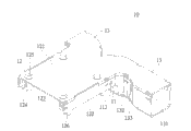
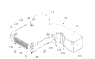
See also Fig. 4 and shown in Figure 5, wind scooper 10 of the present utility model can be applicable in the casing 50 of an electronic installation, these casing 50 inside have a circuit board 51, a radiator 20, reach at least two radiator fans 30, on this circuit board 51 are to be provided with most slots 52 in order to plug memory 53.
This radiator 20 is provided with a pedestal 21 and most fin 22, and pedestal 21 is provided with most perforations 211, and these perforations 211 are corresponding with the through hole 125 of this wind scooper 10, and these fin 22 are that the compartment of terrain is arranged at this pedestal 21 tops.This radiator 20 is arranged on this circuit board 51, and is attached at a heater element (figure does not show) with the bottom surface of this pedestal 21, makes the heat that this heater element produced can see through this pedestal 21 and conduct to these fin 22.
Each radiator fan 30 has a side of giving vent to anger 31 and an air inlet side 32 in contrast to this side 31 of giving vent to anger.This two radiator fan 30 is arranged on the relative both sides of this casing 50, but its air inlet side 32 of mat and sees through the cold air suction of these casing 50 outsides this side 31 of giving vent to anger and blows toward these casing 50 inside.
When this wind scooper 10 is assembled with this radiator 20, please cooperate consult shown in Figure 6, the fastener 126 of this wind scooper 10 is pedestal 21 root edges that are snapped in this radiator 20, and this radiator 20, heater element and interlock circuit are to be contained in the receiving space 123 of this wind scooper 10.In addition, the side 31 of giving vent to anger of this two radiator fan 30 is two air intake vents 131 that are connected respectively in this wind scooper 10.These locking parts 40 are to secure to this casing 50 by the through hole 125 of this wind scooper 10, the perforation 211 of radiator 20 in regular turn, thereby make this wind scooper 10 be installed between this radiator 20 and this two radiator fan 30.
By this, this two radiator fan 30 can be with the cold air suction of these casing 50 outsides and is formed cold airflow, and this cold airflow can import this two air part 13 via two air intake vents 131 of this wind scooper 10 and be pooled in this outlet section 11, after derive and enter in this receiving space 123 by this air outlet 111 again, and blow to this radiator 20 and interlock circuit, thereby the heat that heat that these fin 22 that scatter and disappear are absorbed and interlock circuit produce is reached heat sinking function.
Wherein, because the sectional area of this outlet section 11 is the sectional areas less than this air part 13, therefore, cold airflow (shown in the short arrow among Fig. 4) speed after being pooled to this outlet section 11 that enter this two air part 13 can speed, and formation cold airflow (shown in the long arrow among Fig. 4) faster, the heat that heat that these fin 22 can be absorbed and interlock circuit produce scatters and disappears apace, thereby promotes radiating efficiency further.
In addition, please consult shown in Figure 1 again, this two air part 13 wherein one at the converging transition 132 that can further be provided with a sectional area convergent near the position of this outlet section 11, when making air-flow in entering this air part 13, owing to the reduction of sectional area is speeded the flowing velocity of air-flow, thereby compile toward this outlet section 11 more quickly.
In addition, please consult shown in Figure 1 again, outside the wherein air part 13 of this wind scooper 1 wall near these 11 places, outlet section, and outlet section 11 outside wall near these air part 13 places can further be provided with respectively the perforation 112, the perforation 133, make that air-flow partly can bore a hole 112 via this, perforation 133 blows out, help memory 53 or the heat radiation of other heater element on the wind scooper 10 circuit external plates 51.
Be with, see through the utility model wind scooper, have characteristics described as follows and function:
1, the utility model wind scooper 10 is to utilize most air parts 13 to cooperate with most the radiator fans 30 of position at diverse location, and these radiator fan 30 formed air-flows are compiled, and unified blow to radiator 20 by outlet section 11 and dispel the heat, improve the service efficiency of the air-flow of these radiator fans 30 by this, and utilize the air-flow that doubles quantity to dispel the heat more quickly, thereby reach preferable radiating efficiency.
2, the utility model wind scooper 10 can be designed to the sectional area of outlet section 11 sectional area less than this air part 13, the air-flow that forms by this faster blows to this radiator 20 and interlock circuit, thereby the heat that heat that these fin 22 are absorbed and interlock circuit produce scatters and disappears apace.
3, the utility model wind scooper 10 can be provided with perforation 133, perforation 112 near wall outside these 11 places, outlet section and the outlet section 11 near these air part 13 places at wall outside the air part 13, uses to blow out air-flow partly and help memory 53 or the heat radiation of other heater element.
Above embodiment only is preferred embodiment of the present utility model, and it is illustrative for the utility model, and nonrestrictive.Those skilled in the art carries out conversion, modification even equivalence to it under the situation that does not exceed the utility model spirit and scope, these changes all can fall into claim protection range of the present utility model.

Claims (20)

1, a kind of wind scooper, it is characterized in that, this wind scooper has an outlet section, a cover cap and at least two air parts, this outlet section one end is provided with an air outlet, this cover cap is connected in the end that this outlet section is provided with this air outlet, this cover cap is provided with a receiving space that is communicated with this air outlet, and an end of this two air part is to be connected in the end of this outlet section away from this air outlet jointly, and the other end of this two air part is respectively toward extending away from the direction of this outlet section and respectively being provided with an air intake vent.
2, wind scooper according to claim 1 is characterized in that, the sectional area of this outlet section is less than the sectional area of this air part.
3, wind scooper according to claim 2 is characterized in that, one of them of this two air part is provided with the converging transition of a sectional area convergent in the position near this outlet section.
According to claim 1 or 2 or 3 described wind scoopers, it is characterized in that 4, these cover cap two side bottoms are respectively equipped with most fasteners.
5, wind scooper according to claim 4, it is characterized in that, this cover cap comprises a top board and is arranged at the biside plate of these relative both sides of top board, and this receiving space is to be defined jointly by this top board and this biside plate to form, and these fasteners are down to be extended by this biside plate bottom surface to form.
6, wind scooper according to claim 1 is characterized in that, this cover cap comprises a top board and is arranged at the biside plate of these relative both sides of top board, and this receiving space is to be defined jointly by this top board and this biside plate to form.
7, wind scooper according to claim 6 is characterized in that, this top board is provided with most fixed legs, and each fixed leg inside is provided with a through hole, and these fixed legs are to stretch in this receiving space, and these through holes are to use for most locking parts to wear.
According to claim 1 or 2 or 3 described wind scoopers, it is characterized in that 8, wall is provided with perforation near wall outside this place, outlet section and this outlet section respectively near this air part place outside this air part.
9, wind scooper according to claim 1 is characterized in that, the quantity of these air parts is two and arranges V-shaped.
10, wind scooper according to claim 1, it is characterized in that, this wind scooper comprises one first shell spare and one second shell spare, this first shell spare is provided with most first clamping parts, this second shell spare is provided with most second clamping parts, and these second clamping parts are that correspondence is snapped in these first clamping parts.
11, a kind of wind scooper, in order to be arranged between a radiator and at least two radiator fans, each radiator fan has the side of giving vent to anger, it is characterized in that, this wind scooper has an outlet section, one cover cap, and at least two air parts, this outlet section one end is provided with an air outlet, this cover cap is connected in the end that this outlet section is provided with this air outlet, this cover cap is provided with a receiving space that is communicated with this air outlet, one end of this two air part is to be connected in the end of this outlet section away from this air outlet jointly, and the other end of this two air part is respectively toward extending away from the direction of this outlet section and respectively being provided with an air intake vent;
Wherein this radiator is to be contained in the receiving space of this wind scooper, the side of giving vent to anger of this two radiator fan is to be connected in this two air intake vent, compile in this wind scooper and derive so that the air-flow that this two radiator fan produces imports via this two air intake vent, and enter in this receiving space and blow to this radiator by this air outlet.
12, wind scooper according to claim 11 is characterized in that, the sectional area of this outlet section is less than the sectional area of this air part.
13, wind scooper according to claim 12 is characterized in that, one of them of this two air part is provided with the converging transition of a sectional area convergent in the position near this outlet section.
14, according to claim 11 or 12 or 13 described wind scoopers, it is characterized in that these cover cap two side bottoms are respectively equipped with most fasteners, this radiator is provided with a pedestal and most fin, these fin are to be arranged on this pedestal, and these fasteners are to be snapped in this pedestal root edge.
15, wind scooper according to claim 14, it is characterized in that, this cover cap comprises a top board and is arranged at the biside plate of these relative both sides of top board, and this receiving space is to be defined jointly by this top board and this biside plate to form, and these fasteners are down to be extended by this biside plate bottom surface to form.
16, wind scooper according to claim 11 is characterized in that, this cover cap comprises a top board and is arranged at the biside plate of these relative both sides of top board, and this receiving space is to be defined jointly by this top board and this biside plate to form.
17, wind scooper according to claim 16 is characterized in that, this top board is provided with most fixed legs, and each fixed leg inside is provided with a through hole, and these fixed legs are to stretch in this receiving space, and these through holes are to use for most locking parts to wear.
According to claim 11 or 12 or 13 described wind scoopers, it is characterized in that 18, wall is provided with perforation near wall outside this place, outlet section and this outlet section respectively near this air part place outside this air part.
19, wind scooper according to claim 11 is characterized in that, the quantity of these air parts is two and arranges V-shaped.
20, wind scooper according to claim 11, it is characterized in that, this wind scooper comprises one first shell spare and one second shell spare, this first shell spare is provided with most first clamping parts, this second shell spare is provided with most second clamping parts, and these second clamping parts are that correspondence is snapped in these first clamping parts.
CNU2008201765848U 2008-12-05 2008-12-05 Wind guide cap Expired - Fee Related CN201312471Y (en)

Priority Applications (1)

Application Number Priority Date Filing Date Title
CNU2008201765848U CN201312471Y (en) 2008-12-05 2008-12-05 Wind guide cap

Applications Claiming Priority (1)

Application Number Priority Date Filing Date Title
CNU2008201765848U CN201312471Y (en) 2008-12-05 2008-12-05 Wind guide cap

Publications (1)

Publication Number Publication Date
CN201312471Y true CN201312471Y (en) 2009-09-16

Family

ID=41109727

Family Applications (1)

Application Number Title Priority Date Filing Date
CNU2008201765848U Expired - Fee Related CN201312471Y (en) 2008-12-05 2008-12-05 Wind guide cap

Country Status (1)

Country Link
CN (1) CN201312471Y (en)

Cited By (3)

* Cited by examiner, † Cited by third party
Publication number Priority date Publication date Assignee Title
CN102213984A (en) * 2010-04-09 2011-10-12 鸿富锦精密工业(深圳)有限公司 Heat radiating system
CN102291966A (en) * 2011-08-01 2011-12-21 广东威创视讯科技股份有限公司 Back air cooling device for flat panel display
CN108693937A (en) * 2017-04-11 2018-10-23 鸿富锦精密工业(武汉)有限公司 Radiator

Similar Documents

Publication Publication Date Title
US10362711B2 (en) Fan mounting arrangement in a power supply
CN103809711A (en) Electronic device
US10285306B1 (en) Power supply
CN101201680A (en) Airing cooling system for computer case
CN101193542A (en) Heat radiation device and wind guide sheet
CN211577643U (en) Projector
CN219574753U (en) Indirect liquid cooling assembly and PCIE expansion card
CN201312471Y (en) Wind guide cap
CN101221460A (en) Computer cabinet
CN201358931Y (en) Radiating module with guide effect
CN102647880B (en) Heat abstractor
CN201600640U (en) 2U server wind scooper
EP3493023B1 (en) Power supply
CN102789289A (en) Computer radiating system
CN2733590Y (en) Heat radiator with flow guide cover
CN100464621C (en) Radiating device
CN201486914U (en) Fixing device of fan
CN102958326A (en) Radiating device
CN105682417A (en) Cooling structure of handheld device
CN101165356B (en) Centrifugal fan, heat radiation device possessing the centrifugal fan and electronic device using the heat radiation device
CN108089678B (en) Server wind scooper heat dissipation module
CN203324916U (en) Integrated computer
CN201047926Y (en) Fan fixed structure of computer casing
CN201044077Y (en) Machine case structure and portable computer
CN220603945U (en) Efficient heat dissipation module

Legal Events

Date Code Title Description
C14 Grant of patent or utility model
GR01 Patent grant
ASS Succession or assignment of patent right

Owner name: KAICHUANG RESEARCH CO., LTD.

Free format text: FORMER OWNER: XUNKAI INTERNATIONAL CO., LTD.

Effective date: 20120306

C41 Transfer of patent application or patent right or utility model
TR01 Transfer of patent right

Effective date of registration: 20120306

Address after: Delaware

Patentee after: Kaichuang Research Co., Ltd.

Address before: Taiwan County, Taipei, China

Patentee before: Xunkai International Co., Ltd.

CF01 Termination of patent right due to non-payment of annual fee

Granted publication date: 20090916

Termination date: 20141205

EXPY Termination of patent right or utility model