CN201163445Y - Remote controller emitting set and its remote control system - Google Patents
Remote controller emitting set and its remote control system Download PDFInfo
- Publication number
- CN201163445Y CN201163445Y CNU2008200922714U CN200820092271U CN201163445Y CN 201163445 Y CN201163445 Y CN 201163445Y CN U2008200922714 U CNU2008200922714 U CN U2008200922714U CN 200820092271 U CN200820092271 U CN 200820092271U CN 201163445 Y CN201163445 Y CN 201163445Y
- Authority
- CN
- China
- Prior art keywords
- identification code
- remote
- user
- code
- connects
- Prior art date
- Legal status (The legal status is an assumption and is not a legal conclusion. Google has not performed a legal analysis and makes no representation as to the accuracy of the status listed.)
- Expired - Fee Related
Links
Images


Landscapes
- Selective Calling Equipment (AREA)
- Details Of Television Systems (AREA)
Abstract
The utility model provides an emitter for a remote-control unit and a remote control system for the emitter. The emitter for the remote-control unit comprises a remote control chip and an infrared emitting unit, wherein, a switch unit and a user code selection element are in series connection between a keystroke input and output pin on at least one side of the remote control chip and a custom user code selection end or a direct-current power supply. In the remote control system, an identification code update module which comprises a plurality of preset identification codes is arranged inside a decoding processing unit of an infrared remote control receiver and calls the preset identification codes to update current identification codes in a storage medium. The emitter for the remote-control unit and the remote control system for the emitter effectively avoid the problem of signal interference among a plurality of remote-control units, are simple to reconfigure, and have strong operability and feasibility.
Description
Technical field
The utility model relates to a kind of emission and reception technique of Infrared remote controller, in particular, and a kind of telepilot emitter and telechirics thereof.
Background technology
Infra-red remote control is the widest a kind of remote control means of using at present.Infrared remote controller has characteristics such as volume is little, low in energy consumption, function is strong, cost is low, thereby after colour TV, video recorder, at sound-track engraving apparatus, stereo set, air conditioner, and also adopts infra-red remote control on the set-top box one after another.But the electrical equipment of family is more and more, and telepilot is also more and more, and the possibility that occurs the phase mutual interference between telepilot is just increasing, also can the remote control set-top box such as the telepilot of DVD, and the remote control of set-top box also can be controlled DVD.
The problem that interferes with each other at above-mentioned telepilot, have following settling mode in the prior art: the transmitter unit single-chip microcomputer of remote-control transmitting end is connected with infrared emission unit, and the corresponding I/O mouth of transmitter unit single-chip microcomputer is connected with transmitter unit code character sequence number reset key and transmitter unit code character sequence number options button; In the transmitter unit single-chip microcomputer, solidify the infrared coded program of a cover, in the receiving element single-chip microcomputer, solidified the infrared decoding program of a cover; And but this is overlapped infrared encoding and decoding program is one group by every several different identification codes, is divided into into some groups of effective, the unduplicated code characters of discerning.This scheme can realize realizing having overcome difference remote control for a plurality of identical remotely-controlled objects original telechirics and can cause the problem that interferes with each other with same group of button of a telepilot.But but also there is following problem simultaneously in this solution:
(1) the telepilot end needs a MCU, because be used for being the MCU special-purpose able to programme of remote-control transmitting seldom specially, so do remote control applications with common MCU, its stability, sensitivity and energy saving can be had a greatly reduced quality.(2) need carry out software development to the MCU of telepilot end, be stored in the ROM/FLASH of MCU of telepilot end or outside memory device, the implementation procedure complexity.(3) the telepilot end uses MCU, has increased the cost of telepilot greatly.(4) its technical scheme is difficult to realize.Terminal user's household electrical appliance all are multifarious, and the button of telepilot is of all kinds, have nothing in common with each other, and are difficult to as such scheme, and the function of each telepilot is unified on the telepilot.Remote control such as air-conditioning is united with the remote control of TV with regard to being difficult to.(5) use such scheme, need all electrical equipment of user's family all to use the product of same producer, and when producing, need to set remote control identification code that each electrical equipment uses, it can not be repeated, use a unified telepilot then.Obviously low, the also popularization not too easily of such operation possibility.
Therefore, still need to improve the design of remote manipulator system, make it can solve the above-mentioned problem that interferes with each other effectively.
The utility model content
The purpose of this utility model is to provide a kind of telepilot emitter and telechirics thereof, and it has avoided the problem of signal phase mutual interference between numerous telepilots effectively, and repacking is simple, operability and feasibility are strong.
To achieve these goals, the utility model adopts following technical scheme:
A kind of Infrared Remote-Control Sending device, it comprises: infrared receiver, codec processing unit and storage medium; Be provided with an identification code update module that contains a plurality of default IDs in the described codec processing unit, described identification code update module is called wherein default ID and is upgraded current identification code in the described storage medium.Wherein, described identification code update module comprises: identification code is new database, user instruction resolution unit and identification code selected cell more; Described identification code more new database is used to store described default ID; Described user instruction resolution unit links to each other with the output terminal of described infrared receiver and the input end of described identification code selected cell respectively, be used to resolve the identification code change directive that the user sends by the Infrared Remote-Control Sending device, and this instruction is sent in the described identification code selected cell; Described identification code selected cell also connects described identification code more new database and described storage medium respectively, be used for calling the more identification code that prestores of new database of described identification code, and utilize this identification code to upgrade current identification code in the described storage medium according to the identification code change directive that receives.
The utility model provides a kind of telechirics, described system comprises Infrared Remote-Control Sending device and infrared remote control receiving trap, described Infrared Remote-Control Sending device comprises: remote-controlled chip, infrared emission unit are serially connected with switch element and user code and select components and parts between at least one side button input and output pin of described remote-controlled chip and self-defined user code selecting side or the power supply; Described infrared remote control receiving trap comprises: infrared receiver, codec processing unit and storage medium; The control of described Infrared Remote-Control Sending device and guidance panel are provided with and are used to operate the control structure part that described switch element is closed or disconnect; Be provided with an identification code update module that contains a plurality of default IDs in the described codec processing unit, described identification code update module is called wherein default ID and is upgraded current identification code in the described storage medium.
Wherein, it is diode that described user code is selected components and parts, and the button input and output pin of described remote-controlled chip connects the anode tap of described diode by described switch element, and the cathode terminal of described diode connects described self-defined user code selecting side.Wherein, described identification code update module comprises: identification code is new database, user instruction resolution unit and identification code selected cell more; Described identification code more new database is used to store described default ID; Described user instruction resolution unit links to each other with the output terminal of described infrared receiver and the input end of described identification code selected cell respectively, be used to resolve the identification code change directive that the user sends by the Infrared Remote-Control Sending device, and this instruction is sent in the described identification code selected cell; Described identification code selected cell also connects described identification code more new database and described storage medium respectively, be used for calling the more identification code that prestores of new database of described identification code, and utilize this identification code to upgrade current identification code in the described storage medium according to the identification code change directive that receives.
Wherein, it is pull-up resistor that described user code is selected components and parts, and the button input and output pin of described remote-controlled chip connects an end of described pull-up resistor by described switch element, and the other end of described pull-up resistor connects described dc power output end.Wherein, it is diode that described user code is selected components and parts, and the button input and output pin of described remote-controlled chip connects the anode tap of described diode by described switch element, and the cathode terminal of described diode connects described self-defined user code selecting side.Wherein, described user code selects components and parts to comprise diode and pull-up resistor, and the button input and output pin of described remote-controlled chip connects an end of described pull-up resistor by described switch element, and the other end of described pull-up resistor connects described dc power output end; The anode tap of described diode connects described switch element, and cathode terminal connects described self-defined user code selecting side.
A kind of Infrared Remote-Control Sending device also is provided in the above-mentioned telechirics, it comprises: remote-controlled chip, infrared emission unit are serially connected with switch element and user code and select components and parts between at least one side button input and output pin of described remote-controlled chip and self-defined user code selecting side or the power supply; It is characterized in that the control of described Infrared Remote-Control Sending device and guidance panel are provided with and are used to operate the control structure part that described switch element is closed or disconnect.
Adopt technique scheme, the utility model increases user identification code components and parts and switch element by remote-controlled chip button input and output pin side in infrared launcher, and on the control of Infrared Remote-Control Sending device and guidance panel, be provided with and be used for the control structure part that switch-unit is turn-offed accordingly, thereby realized control to the remote control identification code, if when disturbing appears in remote controller signal, the control structure part that the user only need stir on control and the guidance panel makes the closed or disconnection of switch element, just can optionally adjust identification code, thereby solved the problem that remote controller signal interferes with each other effectively, and transform simple, easy to operate.Certainly, the user need be after the identification code refresh routine that starts the infrared remote control receiving trap upgrades the identification code of receiving end use, change the identification code (passing through toggle switch) of remote control signal transmission device again, the terminating machine at infrared remote control receiving trap place is thought highly of the new back decoding program that starts and is used new remote control identification code work, thereby upgrades identification code each other.
In terms of existing technologies, the technical solution of the utility model is based on present common remote controller scheme, does not need extra MCU, and stability, sensitivity and the energy saving of remote control simultaneously do not have any reduction.And there is not the MCU software development of telepilot end in the utility model, and implementation procedure is simple.Telepilot end of the present utility model has only increased a switch and individual devices, the cost of its increase is relatively low, and the telepilot of terminal user's household electrical appliance is not as any change, need not unify does not need to plan in advance the telepilot identification code of each household electrical appliance in the new telepilot yet.
Description of drawings
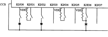
Fig. 1 is the physical circuit figure of the utility model Infrared Remote-Control Sending device;
Fig. 2 is the utility model one embodiment electrical block diagram;
Fig. 3 is the structural representation of the utility model telechirics;
Fig. 4 is the structural representation of identification code update module in the infrared remote control receiving trap;
Fig. 5 is that the user identification code that is applied to the utility model infrared remote control receiving trap on the set-top box is upgraded process flow diagram.
Embodiment
Describe the technical solution of the utility model in detail below in conjunction with accompanying drawing.
As shown in Figure 1, the utility model provides a kind of physical circuit figure of Infrared Remote-Control Sending device, and remote-controlled chip employing model is the integrated chip of CD5022GO among this figure, and it can provide 16 identification codes.Circuit from Fig. 1 as can be seen, the Infrared Remote-Control Sending device comprises: be used to produce coded message remote-controlled chip and external clock unit thereof, be used to launch the infrared emission unit of infrared signal, the keyboard unit that links to each other with remote-controlled chip.As shown in Figure 1, the utility model by described remote-controlled chip button input and output pin (KI/On, n=0,1 ..., 7) side is provided with user code and selects components and parts 200, thereby can control the most-significant byte and/or the least-significant byte of identification code.It can be diode or pull-up resistor that the user here selects components and parts 200, for example, by series diode between the button input and output pin (KI/On) of remote-controlled chip and self-defined user code selecting side CCS, come the self-defined most-significant byte that user identification code is set, if between button input and output pin (KI/On), be connected in series diode, show that then the corresponding positions in most-significant byte is " 1 "; And do not connect diode therebetween, show that then the corresponding positions in most-significant byte is " 0 ".Accordingly, by being connected in series pull-up resistor between the button input and output pin (KI/On) of remote-controlled chip and the direct supply VDD, come the self-defined least-significant byte that user identification code is set, if between button input and output pin (KI/On), be connected in series pull-up resistor, show that then the corresponding positions in least-significant byte is " 1 "; Do not draw resistance and do not connect therebetween, show that then the corresponding positions in least-significant byte is " 0 ".
In addition, also have a kind of situation to be in the motion table, pull-up resistor and diode all are connected on the input and output pin, see Fig. 2, please replenish.
The utility model is on the basis of foregoing circuit structure, button input and output pin (KI/On) and user code at remote-controlled chip are selected also to be in series with a switch element 300 between components and parts 200 or the direct supply, change user identification code by controlling its closure or disconnection, thereby realized to be provided with arbitrarily at any time the function of user identification code.And when specifically telepilot being set, can also be by a control structure part being set in (on the position that can operate for the user) in the control and guidance panel of Infrared Remote-Control Sending device, be used to operate the closed of described switch element or disconnect, thereby make the user can change the operation of user identification code more convenient, quickly, such as switch element 300 can be toggle switch, corresponding operating just need be set on control and guidance panel so be used for gauge tap disconnection or closed.Certainly there is no need user code selection components and parts all to be set in button input and output pin (KI/On) side of each remote-controlled chip, so, in infrared launcher of the present utility model, as long as it is passable that remote-controlled chip has at least one button input and output pin (KI/On) side to be provided with once the circuit structure of selecting components and parts to constitute by switch element and user code, that is to say, have at least between a button input and output pin (KI/On) and the self-defined user code selecting side CCS to be in series with a circuit structure that constitutes by diode and switch element, perhaps have at least between the output terminal of a button input and output pin (KI/On) and direct supply VDD to be in series with a circuit structure that constitutes by pull-up resistor and switch element.Here switch element 300, the utility model that is provided with of its position does not limit, it can be arranged on button input and output pin (KI/On) and user code and select between the components and parts 200, also can be arranged on user code and select between components and parts 200 and the self-defined user code selecting side CCS or user code is selected between the output terminal of components and parts 200 and direct supply VDD.As shown in Figure 2, the switch element here adopts the switch of common single channel control, when button input and output pin (KI/O6) connects diode and pull-up resistor simultaneously, switch is arranged on user code selects between components and parts 200 and the button input and output pin (KI/O6) more betterly, can reduce the use number of switch.Below will illustrate the present invention at circuit shown in Figure 2 and how change identification code.
As shown in Figure 2, the button input and output pin KI/O0 of remote-controlled chip, KI/O2, KI/O6 connect the anode tap of diode respectively by a switch, and the cathode terminal of diode connects the self-defined user code selecting side CCS of remote-controlled chip then; And button input and output pin KI/O1, KI/O4, KI/O6 also connect an end of a pull-up resistor respectively by a switch, and the other end of pull-up resistor connects described direct supply VDD output terminal.If the switch among Fig. 2 is all closed, then the most-significant byte IH of identification code is 10100010, and the state RS of resistance is 01001010, and the least-significant byte IL of identification code to be IH identical with RS or, be 00010111.Whole like this identification code is 10100010,00010111.If only closed a part of switch, then identification code just changes accordingly, thereby has realized the function of random adjustment user identification code.
In the technique scheme, the utility model mainly is being illustrated for example of CD5022 with the model, but can adopt other to realize the chip of identical function equally, as model is the chip of CD5021 or HT6221, in HT6221, its AIN pin correspondence be exactly the above-mentioned self-defined user code selecting side CUSTOM CODE SELECT that mentions.
Based on above-mentioned improvement to physical circuit, the utility model also provides a kind of telechirics, as shown in Figure 3, described system comprises Infrared Remote-Control Sending device 400 and infrared remote control receiving trap 500, and described infrared remote control receiving trap 500 comprises: be used to receive infrared receiver 50 1, the codec processing unit 502 that is used to decode of infrared signal and be used to store the storage medium 504 of identification code; And the Infrared Remote-Control Sending device 400 here is exactly to adopt the above-mentioned Infrared Remote-Control Sending circuit structure of mentioning, and in the infrared remote control receiving trap 500 here, be provided with an identification code update module 503 that contains a plurality of default IDs in its codec processing unit 502, identification code update module 503 is used for calling the current identification code of default ID updated stored medium wherein.Here the default ID in the identification code update module 503 is corresponding with the new identification code that adjusting Infrared Remote-Control Sending device 400 is produced.And identification code update module described here can comprise as shown in Figure 3: be used to store prestore identification code more new database 525, user instruction resolution unit 513 and the identification code selected cell 523 of identification code; User instruction resolution unit 513 links to each other with the output terminal of infrared receiver 501 and the input end of identification code selected cell 523 respectively, be used to resolve the identification code change directive that the user sends by Infrared Remote-Control Sending device 400, and this instruction is sent in the identification code selected cell 523; Identification code selected cell 523 also connects identification code more new database 525 and storage medium 504 respectively, be used for calling the more identification code that prestores of new database 525 of identification code, and utilize the current identification code in this identification code updated stored medium 504 according to the identification code change directive that receives.Identification code update module 503 shown in Figure 3 can realize by software, and play the function of identification code refresh routine.From foregoing as can be known, the utility model also provides a kind of novel infrared remote control receiving trap 500.
Usually user identification code all is to be kept in the storage medium 504 (as FLASH) of infrared remote control receiving trap 500, during each remote control procedure initialization, this value is read out be directly used in decoding program.But when interfering with each other appears in telepilot, the user need start the identification code that identification code update module in the infrared remote control receiving trap 500 is upgraded the current use of receiving end, the terminal at infrared remote control receiving trap 500 places is stored to the new identification code that the user selects in the storage medium 504 then, after infrared receiving device 500 restarts, correspondence is stirred the user identification code that the toggle switch that is positioned on the Infrared Remote-Control Sending device 400 is revised the telepilot end, make infrared remote control receiving trap 500 upgrade existing user identification code by software operation like this, and guaranteed no longer to occur between the telepilot problem of phase mutual interference.
With the infrared remote control receiving trap that is applied on the set-top box is example, and the Infrared Remote-Control Sending device is arranged on the telepilot.In the present embodiment, suppose that the identification code update module on the set-top box contains two alternative identification code A or B, and these two identification code A or B can set by toggle switch at the telepilot end; Corresponding, operation can be set two buttons (as " 1 " and " 2 " button) and represent above-mentioned two identification code A or B respectively on the telepilot control panel for the convenience of the user, in order to be user-friendly to telepilot identification code is selected.Flow process is carried out change work to the remote control identification code as shown in Figure 5, needs to be set with two state variables in this flow process, and the initial value of " telepilot identification code allow upgrade " is for being that the preliminary examination value of " identification code begins to upgrade " is for denying.
S600 after set-top box powers on, judges whether that according to user's needs needs enter identification code change program.Set-top-box system can be set a certain button as the switch that enters identification code change program, shows that such as setting long MENU key 3 stopwatches by set top box front panel in this flow process the user need enter identification code change state.Among Fig. 5,, then can enter identification code change state by execution in step S601 when the user need change the telepilot identification code; If the user does not need to change the telepilot identification code, then enter normal button handling procedure by execution in step S602;
S601, the user enters telepilot identification code change state by long 3 seconds by front panel MENU, certainly at this moment, the handling procedure of set-top box inside need reach 3 default seconds by judging whether the user grows by this key, if do not reach Preset Time, then enter normal button handling procedure by execution in step S602; But if reach Preset Time, then the change of the identification code by set-top box inside program provides prompting " identification code begins renewal " on television interfaces, and provides corresponding man-machine interface and make things convenient for the user to carry out next step operation.After prompting on the television interfaces " identification code begins to upgrade ", the user selects identification code A or B by " 1 " or " 2 " of telepilot earlier, and then by the acknowledgement key that on telecontrol panel, is provided with in advance, in order to the identification code of confirming to select, the operation of the program of the identification code of set-top box inside change at this moment recording user, and call default ID A or the B that is kept at set-top box inside in advance according to user's operational order, utilize the current identification code in the new identification code updated stored medium that the user selects, and the set-top box that resets automatically, the set box remote control system carries out decoding work with regard to utilizing new identification code;
S602, it is not that the identification code change program of set-top box inside is put " permission of telepilot identification code is upgraded ", and by normal button handling procedure, current identification code is carried out decoding processing in the use storage medium;
S603 finishes one-touch and handles.
Certainly, flow process shown in Figure 4 can also be applied on other terminal machines that adopt technical solutions of the utility model through adaptability revision.
Should be understood that, for those of ordinary skills, can be improved according to the above description or conversion, and all these improvement and conversion all should belong to the protection domain of the utility model claims.
Claims (12)
1, a kind of infrared remote control receiving trap, described infrared remote control receiving trap comprises: infrared receiver, codec processing unit and storage medium; It is characterized in that, be provided with an identification code update module that contains a plurality of default IDs in the described codec processing unit, described identification code update module is called wherein default ID and is upgraded current identification code in the described storage medium.
2, infrared remote control receiving trap according to claim 1 is characterized in that, described identification code update module comprises: identification code is new database, user instruction resolution unit and identification code selected cell more;
Described identification code more new database is used to store described default ID;
Described user instruction resolution unit links to each other with the output terminal of described infrared receiver and the input end of described identification code selected cell respectively, be used to resolve the identification code change directive that the user sends by the Infrared Remote-Control Sending device, and this instruction is sent in the described identification code selected cell;
Described identification code selected cell also connects described identification code more new database and described storage medium respectively, be used for calling the more identification code that prestores of new database of described identification code, and utilize this identification code to upgrade current identification code in the described storage medium according to the identification code change directive that receives.
3, a kind of telechirics, described system comprises Infrared Remote-Control Sending device and infrared remote control receiving trap, described Infrared Remote-Control Sending device comprises: remote-controlled chip, infrared emission unit are serially connected with switch element and user code and select components and parts between at least one side button input and output pin of described remote-controlled chip and self-defined user code selecting side or the direct supply; Described infrared remote control receiving trap comprises: infrared receiver, codec processing unit and storage medium; It is characterized in that the control of described Infrared Remote-Control Sending device and guidance panel are provided with and are used to operate the control structure part that described switch element is closed or disconnect; Be provided with an identification code update module that contains a plurality of default IDs in the described codec processing unit, described identification code update module is called wherein default ID and is upgraded current identification code in the described storage medium.
4, telechirics according to claim 3, it is characterized in that, it is diode that described user code is selected components and parts, the button input and output pin of described remote-controlled chip connects the anode tap of described diode by described switch element, and the cathode terminal of described diode connects described self-defined user code selecting side.
5, telechirics according to claim 3 is characterized in that, described identification code update module comprises: identification code is new database, user instruction resolution unit and identification code selected cell more;
Described identification code more new database is used to store described default ID;
Described user instruction resolution unit links to each other with the output terminal of described infrared receiver and the input end of described identification code selected cell respectively, be used to resolve the identification code change directive that the user sends by the Infrared Remote-Control Sending device, and this instruction is sent in the described identification code selected cell;
Described identification code selected cell also connects described identification code more new database and described storage medium respectively, be used for calling the more identification code that prestores of new database of described identification code, and utilize this identification code to upgrade current identification code in the described storage medium according to the identification code change directive that receives.
6, telechirics according to claim 3, it is characterized in that, it is pull-up resistor that described user code is selected components and parts, the button input and output pin of described remote-controlled chip connects an end of described pull-up resistor by described switch element, and the other end of described pull-up resistor connects described dc power output end.
7, telechirics according to claim 3, it is characterized in that, it is diode that described user code is selected components and parts, the button input and output pin of described remote-controlled chip connects the anode tap of described diode by described switch element, and the cathode terminal of described diode connects described self-defined user code selecting side.
8, telechirics according to claim 3, it is characterized in that, described user code selects components and parts to comprise diode and pull-up resistor, the button input and output pin of described remote-controlled chip connects an end of described pull-up resistor by described switch element, and the other end of described pull-up resistor connects described dc power output end; The anode tap of described diode connects described switch element, and cathode terminal connects described self-defined user code selecting side.
9, a kind of Infrared Remote-Control Sending device, it comprises: remote-controlled chip, infrared emission unit are serially connected with switch element and user code and select components and parts between at least one side button input and output pin of described remote-controlled chip and self-defined user code selecting side or the power supply; It is characterized in that the control of described Infrared Remote-Control Sending device and guidance panel are provided with and are used to operate the control structure part that described switch element is closed or disconnect.
10, Infrared Remote-Control Sending device according to claim 9, it is characterized in that, it is diode that described user code is selected components and parts, the button input and output pin of described remote-controlled chip connects the anode tap of described diode by described switch element, and the cathode terminal of described diode connects described self-defined user code selecting side.
11, Infrared Remote-Control Sending device according to claim 9, it is characterized in that, it is pull-up resistor that described user code is selected components and parts, the button input and output pin of described remote-controlled chip connects an end of described pull-up resistor by described switch element, and the other end of described pull-up resistor connects described dc power output end.
12, Infrared Remote-Control Sending device according to claim 9, it is characterized in that, described user code selects components and parts to comprise diode and pull-up resistor, the button input and output pin of described remote-controlled chip connects an end of described pull-up resistor by described switch element, and the other end of described pull-up resistor connects described dc power output end; The anode tap of described diode connects described switch element, and cathode terminal connects described self-defined user code selecting side.
Priority Applications (1)
| Application Number | Priority Date | Filing Date | Title |
|---|---|---|---|
| CNU2008200922714U CN201163445Y (en) | 2008-02-04 | 2008-02-04 | Remote controller emitting set and its remote control system |
Applications Claiming Priority (1)
| Application Number | Priority Date | Filing Date | Title |
|---|---|---|---|
| CNU2008200922714U CN201163445Y (en) | 2008-02-04 | 2008-02-04 | Remote controller emitting set and its remote control system |
Publications (1)
| Publication Number | Publication Date |
|---|---|
| CN201163445Y true CN201163445Y (en) | 2008-12-10 |
Family
ID=40184375
Family Applications (1)
| Application Number | Title | Priority Date | Filing Date |
|---|---|---|---|
| CNU2008200922714U Expired - Fee Related CN201163445Y (en) | 2008-02-04 | 2008-02-04 | Remote controller emitting set and its remote control system |
Country Status (1)
| Country | Link |
|---|---|
| CN (1) | CN201163445Y (en) |
Cited By (7)
| Publication number | Priority date | Publication date | Assignee | Title |
|---|---|---|---|---|
| CN102651161A (en) * | 2011-02-28 | 2012-08-29 | 冠捷投资有限公司 | Remote controller with remote updating function |
| WO2014173248A1 (en) * | 2013-04-24 | 2014-10-30 | 广东欧珀移动通信有限公司 | Method and device for matching customer code of remote controller |
| WO2014187036A1 (en) * | 2013-05-22 | 2014-11-27 | 京东方科技集团股份有限公司 | Remote controller, television and remote control method |
| WO2016023312A1 (en) * | 2014-08-13 | 2016-02-18 | 深圳Tcl新技术有限公司 | Infrared remote control signal converter and remote control system |
| CN105657504A (en) * | 2015-12-31 | 2016-06-08 | 深圳创维数字技术有限公司 | Remote controller upgrading method and set-top box |
| CN108417011A (en) * | 2018-04-27 | 2018-08-17 | 上海中基国威电子股份有限公司 | A kind of programmable Infrared Remote-Control Sending circuit of the erasable multisystem of repetition |
| CN108961734A (en) * | 2018-07-24 | 2018-12-07 | 珠海格力电器股份有限公司 | Infrared semantic processes method, apparatus and system |
-
2008
- 2008-02-04 CN CNU2008200922714U patent/CN201163445Y/en not_active Expired - Fee Related
Cited By (9)
| Publication number | Priority date | Publication date | Assignee | Title |
|---|---|---|---|---|
| CN102651161A (en) * | 2011-02-28 | 2012-08-29 | 冠捷投资有限公司 | Remote controller with remote updating function |
| WO2014173248A1 (en) * | 2013-04-24 | 2014-10-30 | 广东欧珀移动通信有限公司 | Method and device for matching customer code of remote controller |
| WO2014187036A1 (en) * | 2013-05-22 | 2014-11-27 | 京东方科技集团股份有限公司 | Remote controller, television and remote control method |
| CN104184970A (en) * | 2013-05-22 | 2014-12-03 | 京东方科技集团股份有限公司 | Remote controller, television and remote control method |
| CN104184970B (en) * | 2013-05-22 | 2016-06-29 | 京东方科技集团股份有限公司 | Remote controller, television set and remote control thereof |
| WO2016023312A1 (en) * | 2014-08-13 | 2016-02-18 | 深圳Tcl新技术有限公司 | Infrared remote control signal converter and remote control system |
| CN105657504A (en) * | 2015-12-31 | 2016-06-08 | 深圳创维数字技术有限公司 | Remote controller upgrading method and set-top box |
| CN108417011A (en) * | 2018-04-27 | 2018-08-17 | 上海中基国威电子股份有限公司 | A kind of programmable Infrared Remote-Control Sending circuit of the erasable multisystem of repetition |
| CN108961734A (en) * | 2018-07-24 | 2018-12-07 | 珠海格力电器股份有限公司 | Infrared semantic processes method, apparatus and system |
Similar Documents
| Publication | Publication Date | Title |
|---|---|---|
| CN201163445Y (en) | Remote controller emitting set and its remote control system | |
| US8232861B2 (en) | Remote controller capable of selectively controlling a plurality of electric appliances, remote control system and method thereof | |
| CN102662380A (en) | Concentrative networking control method and system for family electric appliances | |
| CN102592435B (en) | Method for remotely controlling electronic device and mobile terminal | |
| CN101719998B (en) | Centralized control system and method of domestic appliances | |
| CN100566389C (en) | Television set | |
| CN103079021A (en) | Method, system and device for controlling intelligent household electrical appliance through mobile terminal | |
| CN202907115U (en) | Secondary remote control device, television and remote control system | |
| CN102253805A (en) | Remote control device and realizing method thereof | |
| CN100399372C (en) | Integral remote control method for household electrical equipment | |
| CN103873905A (en) | Television control system and television control method | |
| CN101488282B (en) | Method for remote controlling television set by set-top box | |
| CN103905872A (en) | Method and device for controlling multi-device system | |
| CN102098461A (en) | Remote control system and remote control method thereof | |
| CN103092097A (en) | Household appliance control method and system based on intelligent television | |
| CN202523209U (en) | Infrared remote control device | |
| CN103176446A (en) | Home appliance control method and home appliance control system based on set top box | |
| CN105025398A (en) | Wireless remote control integration system | |
| CN104766465A (en) | General remote controller | |
| CN203084921U (en) | Intelligent equipment-based remote household appliance control terminal | |
| CN201122965Y (en) | Intelligent household control device | |
| CN101640767A (en) | TV remote-control method based on set-top box | |
| CN100385471C (en) | Studying remote control method and device for household electrical appliances | |
| CN101621610B (en) | Television controlling camera | |
| CN206728212U (en) | A kind of control device based on set top box |
Legal Events
| Date | Code | Title | Description |
|---|---|---|---|
| C14 | Grant of patent or utility model | ||
| GR01 | Patent grant | ||
| CF01 | Termination of patent right due to non-payment of annual fee |
Granted publication date: 20081210 Termination date: 20150204 |
|
| EXPY | Termination of patent right or utility model |