CN201142047Y - 1U cabinet heat radiating device making use of radiation - Google Patents
1U cabinet heat radiating device making use of radiation Download PDFInfo
- Publication number
- CN201142047Y CN201142047Y CNU2008200220177U CN200820022017U CN201142047Y CN 201142047 Y CN201142047 Y CN 201142047Y CN U2008200220177 U CNU2008200220177 U CN U2008200220177U CN 200820022017 U CN200820022017 U CN 200820022017U CN 201142047 Y CN201142047 Y CN 201142047Y
- Authority
- CN
- China
- Prior art keywords
- cpu
- radiating
- heat
- radiation
- radiating fin
- Prior art date
- Legal status (The legal status is an assumption and is not a legal conclusion. Google has not performed a legal analysis and makes no representation as to the accuracy of the status listed.)
- Expired - Fee Related
Links
- 230000005855 radiation Effects 0.000 title claims description 23
- 230000009286 beneficial effect Effects 0.000 claims description 8
- 230000017525 heat dissipation Effects 0.000 claims description 5
- 238000009423 ventilation Methods 0.000 claims description 2
- 238000005516 engineering process Methods 0.000 description 3
- 238000007664 blowing Methods 0.000 description 1
- 238000001816 cooling Methods 0.000 description 1
- 238000010586 diagram Methods 0.000 description 1
- 230000000694 effects Effects 0.000 description 1
- 238000009434 installation Methods 0.000 description 1
- 238000012423 maintenance Methods 0.000 description 1
- 230000014759 maintenance of location Effects 0.000 description 1
Images

Landscapes
- Cooling Or The Like Of Electrical Apparatus (AREA)
Abstract
The utility model provides a radiating device of a 1U casing, which facilitate heat dissipating. The radiating device comprises a computer CPU, a CPU radiating plate, air guiding hoods and a turbo fan. The CPU radiating plate is fixedly arranged on the computer CPU, one side of the CPU radiating plate is fixedly connected with one air guiding hood which is provided with a transverse air duct, and the other end of the air guiding hood is connected with the turbo fan. The radiating air duct between fins of the CPU radiating plate and the air duct of the air guiding hood are in parallel. The radiating device of the 1U casing has reasonable design and simple structure, greatly improves the radiating efficiency, and is suitable for radiating the 1U casing, thus being of good popularization and use value.
Description
1, technical field
The utility model relates to a kind of computer system heat radiation technology, specifically a kind of 1U case radiation device that is beneficial to heat radiation.
2, background technology
For rack-mount server, the size of server volume has directly determined cost of system maintenance.Yet along with the integrated level of computer system is more and more higher, the thermal value of each accessory is increasing in the cabinet, requires the heat-dissipating space in the cabinet also increasing.Simultaneously, the utilization of the heat radiator of large volume and powerful fan need take more clearance spaces.For the 1U server, keep cabinet volume and raising radiating efficiency to become an important contradiction.
Now, the heat radiation of computer system is subjected to manufacturer and user's great attention, and fan has played very big effect in heat dissipation system for computers, be the defender of the normal steady operation of computing machine as used fans such as computer CPU, cabinet, video card and power supplys.
For the 1U server, known heat dissipation technology is for fixedly mounting CPU radiating fin, fan of CPU radiating fin top fixed installation on CPU.Because the 1U server for the restriction of cabinet height, makes the size of heat radiator, the power of fan also has been subjected to certain restriction, can't improve radiating efficiency again.
3, summary of the invention
The purpose of this utility model is to overcome above-mentioned shortcoming, and a kind of more 1U case radiation device that is beneficial to heat radiation of high cooling efficiency that has is provided.
The technical solution of the utility model realizes in the following manner, by changing the positional structure of computer system heat radiation sheet and fan, can make the heat radiator in the 1U cabinet have bigger volume and area of dissipation, the power that adds big fan simultaneously, adopt the mode of directly blowing that CPU is dispelled the heat, improved radiating efficiency.The 1U case radiation device that this is beneficial to heat radiation comprises computer CPU, CPU radiating fin, wind scooper and turbofan.On computer CPU, be set with CPU radiating fin, the fixedly connected wind scooper of CPU radiating fin one side with transversal ventilation road, the other end of wind scooper connects turbofan.Heat dissipation wind channel between the CPU radiating fin fin parallels with the ventiduct of wind scooper.
The utility model has the advantages that:
1, the straight blow type radiating mode effectively forms the inner high blast of heat radiator and spreads air-flow by force, takes away internal heat rapidly;
2, rationally arrange the interior accessory position of cabinet, increased the volume of CPU radiating fin and the power of turbofan, improved radiating efficiency greatly.
4, description of drawings
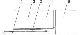
The structural representation of the 1U case radiation device that accompanying drawing 1 for the benefit of dispels the heat.
The wind scooper connection diagram of the 1U case radiation device that accompanying drawing 2 for the benefit of dispels the heat.
Mark in the accompanying drawing is represented respectively: mainboard 1, CPU2, heat radiator 3, wind scooper 4, turbofan 5, screw 6.
5, embodiment
Below in conjunction with accompanying drawing the 1U case radiation device that is beneficial to heat radiation of the present utility model is done following detailed description the in detail.
As shown in Figure 1, in the 1U cabinet, be provided with mainboard 1, CPU2, CPU radiating fin 3, wind scooper 4 and turbofan 5.The two ends of wind scooper 4 ventilating openings connect CPU radiating fin 3 and turbofan 5 air outlets respectively.The top panel of wind scooper 4 covers heat radiator 3 tops, and is fixed on the heat radiator 3 by screw 6.On the cabinet of mainboard 1 one sides, this turbofan adopts high-power turbofan 5 by screw retention, the fan that heat radiator 3 is directly blown.
As shown in Figure 2, on the CPU seat of mainboard 1 CPU2 is installed, heat radiator 3 is fixed on the CPU2 top, and contacts with the heat radiation wafer of CPU2.The right side of CPU2 is equipped with turbofan 5, and heat radiator 3 is connected by middle wind scooper 4 with turbofan 5.Heat dissipation channel between CPU radiating fin 3 fins parallels with the ventiduct of wind scooper.
The 1U case radiation device that is beneficial to heat radiation of the present utility model is reasonable in design, simple in structure, safe and reliable, easy to use, has improved the radiating efficiency of computer system effectively, thereby, have good value for applications.
Claims (2)
1, is beneficial to the 1U case radiation device of heat radiation, comprise computer CPU, CPU radiating fin and turbofan, it is characterized in that being set with on the computer CPU CPU radiating fin, the fixedly connected wind scooper of CPU radiating fin with transversal ventilation road, the other end of wind scooper connects turbofan.
2, the 1U case radiation device that is beneficial to heat radiation according to claim 1 is characterized in that the heat dissipation wind channel between the CPU radiating fin fin parallels with the ventiduct of wind scooper.
Priority Applications (1)
| Application Number | Priority Date | Filing Date | Title |
|---|---|---|---|
| CNU2008200220177U CN201142047Y (en) | 2008-01-03 | 2008-01-03 | 1U cabinet heat radiating device making use of radiation |
Applications Claiming Priority (1)
| Application Number | Priority Date | Filing Date | Title |
|---|---|---|---|
| CNU2008200220177U CN201142047Y (en) | 2008-01-03 | 2008-01-03 | 1U cabinet heat radiating device making use of radiation |
Publications (1)
| Publication Number | Publication Date |
|---|---|
| CN201142047Y true CN201142047Y (en) | 2008-10-29 |
Family
ID=40069757
Family Applications (1)
| Application Number | Title | Priority Date | Filing Date |
|---|---|---|---|
| CNU2008200220177U Expired - Fee Related CN201142047Y (en) | 2008-01-03 | 2008-01-03 | 1U cabinet heat radiating device making use of radiation |
Country Status (1)
| Country | Link |
|---|---|
| CN (1) | CN201142047Y (en) |
Cited By (2)
| Publication number | Priority date | Publication date | Assignee | Title |
|---|---|---|---|---|
| CN103329641A (en) * | 2010-12-01 | 2013-09-25 | 谷歌公司 | Cooling heat-generating electronics |
| CN106292946A (en) * | 2015-06-09 | 2017-01-04 | 天津神为科技有限公司 | A kind of inner evaporation cooling 1U server |
-
2008
- 2008-01-03 CN CNU2008200220177U patent/CN201142047Y/en not_active Expired - Fee Related
Cited By (2)
| Publication number | Priority date | Publication date | Assignee | Title |
|---|---|---|---|---|
| CN103329641A (en) * | 2010-12-01 | 2013-09-25 | 谷歌公司 | Cooling heat-generating electronics |
| CN106292946A (en) * | 2015-06-09 | 2017-01-04 | 天津神为科技有限公司 | A kind of inner evaporation cooling 1U server |
Similar Documents
| Publication | Publication Date | Title |
|---|---|---|
| CN100383702C (en) | Improved structure of server | |
| CN201138463Y (en) | Computer system with wind-guiding cowl | |
| CN201440775U (en) | Heat emission air guiding structure for electronic equipment | |
| CN203377773U (en) | Frequency inverter heat dissipation structure | |
| CN201226633Y (en) | Electronic device with radiating system | |
| CN201008247Y (en) | Large scale switch matrix cabinet | |
| CN101221460A (en) | Computer cabinet | |
| CN102419624A (en) | Air guiding heat dissipation device for computer | |
| CN201142047Y (en) | 1U cabinet heat radiating device making use of radiation | |
| CN102196714A (en) | Heat dissipation device | |
| TW201227242A (en) | Heat dissipation system and container using the same | |
| CN201600640U (en) | 2U server wind scooper | |
| CN201440781U (en) | Radiating module and air current guide piece thereof | |
| CN201876798U (en) | Heat radiation device for computer case | |
| CN203167506U (en) | Heat radiating structure and equipment with heat radiating structure | |
| CN210864590U (en) | Supplementary heat dissipation formula all-in-one | |
| CN202548749U (en) | Chassis cooling device for computer host | |
| CN2833702Y (en) | Novel computer wind scooper | |
| CN202026555U (en) | Heat radiation device | |
| CN206672004U (en) | A kind of outer surface heat abstractor | |
| CN202372911U (en) | Air deflecting and radiating device for computer | |
| CN202189298U (en) | Terminal device | |
| CN201541417U (en) | Auxiliary heat dissipating system of communication cabinet | |
| CN2857221Y (en) | Heat radiator with air guide sleeve | |
| TWM249105U (en) | Cooling module of computer system and related apparatus with air wall for preventing recycling of heated air |
Legal Events
| Date | Code | Title | Description |
|---|---|---|---|
| C14 | Grant of patent or utility model | ||
| GR01 | Patent grant | ||
| C17 | Cessation of patent right | ||
| CF01 | Termination of patent right due to non-payment of annual fee |
Granted publication date: 20081029 Termination date: 20110103 |