CN1729470A - Securing device for a security module connector - Google Patents
Securing device for a security module connector Download PDFInfo
- Publication number
- CN1729470A CN1729470A CNA2003801069606A CN200380106960A CN1729470A CN 1729470 A CN1729470 A CN 1729470A CN A2003801069606 A CNA2003801069606 A CN A2003801069606A CN 200380106960 A CN200380106960 A CN 200380106960A CN 1729470 A CN1729470 A CN 1729470A
- Authority
- CN
- China
- Prior art keywords
- label
- antenna
- security module
- chip
- transmitter
- Prior art date
- Legal status (The legal status is an assumption and is not a legal conclusion. Google has not performed a legal analysis and makes no representation as to the accuracy of the status listed.)
- Pending
Links
Images

Classifications
-
- H—ELECTRICITY
- H01—ELECTRIC ELEMENTS
- H01R—ELECTRICALLY-CONDUCTIVE CONNECTIONS; STRUCTURAL ASSOCIATIONS OF A PLURALITY OF MUTUALLY-INSULATED ELECTRICAL CONNECTING ELEMENTS; COUPLING DEVICES; CURRENT COLLECTORS
- H01R13/00—Details of coupling devices of the kinds covered by groups H01R12/70 or H01R24/00 - H01R33/00
- H01R13/58—Means for relieving strain on wire connection, e.g. cord grip, for avoiding loosening of connections between wires and terminals within a coupling device terminating a cable
-
- G—PHYSICS
- G06—COMPUTING; CALCULATING OR COUNTING
- G06K—GRAPHICAL DATA READING; PRESENTATION OF DATA; RECORD CARRIERS; HANDLING RECORD CARRIERS
- G06K19/00—Record carriers for use with machines and with at least a part designed to carry digital markings
- G06K19/06—Record carriers for use with machines and with at least a part designed to carry digital markings characterised by the kind of the digital marking, e.g. shape, nature, code
- G06K19/067—Record carriers with conductive marks, printed circuits or semiconductor circuit elements, e.g. credit or identity cards also with resonating or responding marks without active components
- G06K19/07—Record carriers with conductive marks, printed circuits or semiconductor circuit elements, e.g. credit or identity cards also with resonating or responding marks without active components with integrated circuit chips
- G06K19/073—Special arrangements for circuits, e.g. for protecting identification code in memory
- G06K19/07309—Means for preventing undesired reading or writing from or onto record carriers
- G06K19/07372—Means for preventing undesired reading or writing from or onto record carriers by detecting tampering with the circuit
- G06K19/07381—Means for preventing undesired reading or writing from or onto record carriers by detecting tampering with the circuit with deactivation or otherwise incapacitation of at least a part of the circuit upon detected tampering
-
- G—PHYSICS
- G06—COMPUTING; CALCULATING OR COUNTING
- G06K—GRAPHICAL DATA READING; PRESENTATION OF DATA; RECORD CARRIERS; HANDLING RECORD CARRIERS
- G06K19/00—Record carriers for use with machines and with at least a part designed to carry digital markings
- G06K19/06—Record carriers for use with machines and with at least a part designed to carry digital markings characterised by the kind of the digital marking, e.g. shape, nature, code
- G06K19/067—Record carriers with conductive marks, printed circuits or semiconductor circuit elements, e.g. credit or identity cards also with resonating or responding marks without active components
- G06K19/07—Record carriers with conductive marks, printed circuits or semiconductor circuit elements, e.g. credit or identity cards also with resonating or responding marks without active components with integrated circuit chips
- G06K19/073—Special arrangements for circuits, e.g. for protecting identification code in memory
-
- G—PHYSICS
- G06—COMPUTING; CALCULATING OR COUNTING
- G06K—GRAPHICAL DATA READING; PRESENTATION OF DATA; RECORD CARRIERS; HANDLING RECORD CARRIERS
- G06K19/00—Record carriers for use with machines and with at least a part designed to carry digital markings
- G06K19/06—Record carriers for use with machines and with at least a part designed to carry digital markings characterised by the kind of the digital marking, e.g. shape, nature, code
- G06K19/067—Record carriers with conductive marks, printed circuits or semiconductor circuit elements, e.g. credit or identity cards also with resonating or responding marks without active components
- G06K19/07—Record carriers with conductive marks, printed circuits or semiconductor circuit elements, e.g. credit or identity cards also with resonating or responding marks without active components with integrated circuit chips
- G06K19/077—Constructional details, e.g. mounting of circuits in the carrier
- G06K19/07749—Constructional details, e.g. mounting of circuits in the carrier the record carrier being capable of non-contact communication, e.g. constructional details of the antenna of a non-contact smart card
- G06K19/07758—Constructional details, e.g. mounting of circuits in the carrier the record carrier being capable of non-contact communication, e.g. constructional details of the antenna of a non-contact smart card arrangements for adhering the record carrier to further objects or living beings, functioning as an identification tag
- G06K19/0776—Constructional details, e.g. mounting of circuits in the carrier the record carrier being capable of non-contact communication, e.g. constructional details of the antenna of a non-contact smart card arrangements for adhering the record carrier to further objects or living beings, functioning as an identification tag the adhering arrangement being a layer of adhesive, so that the record carrier can function as a sticker
-
- G—PHYSICS
- G06—COMPUTING; CALCULATING OR COUNTING
- G06K—GRAPHICAL DATA READING; PRESENTATION OF DATA; RECORD CARRIERS; HANDLING RECORD CARRIERS
- G06K19/00—Record carriers for use with machines and with at least a part designed to carry digital markings
- G06K19/06—Record carriers for use with machines and with at least a part designed to carry digital markings characterised by the kind of the digital marking, e.g. shape, nature, code
- G06K19/067—Record carriers with conductive marks, printed circuits or semiconductor circuit elements, e.g. credit or identity cards also with resonating or responding marks without active components
- G06K19/07—Record carriers with conductive marks, printed circuits or semiconductor circuit elements, e.g. credit or identity cards also with resonating or responding marks without active components with integrated circuit chips
- G06K19/077—Constructional details, e.g. mounting of circuits in the carrier
- G06K19/07749—Constructional details, e.g. mounting of circuits in the carrier the record carrier being capable of non-contact communication, e.g. constructional details of the antenna of a non-contact smart card
- G06K19/07798—Constructional details, e.g. mounting of circuits in the carrier the record carrier being capable of non-contact communication, e.g. constructional details of the antenna of a non-contact smart card part of the antenna or the integrated circuit being adapted for rupturing or breaking, e.g. record carriers functioning as sealing devices for detecting not-authenticated opening of containers
-
- G—PHYSICS
- G06—COMPUTING; CALCULATING OR COUNTING
- G06K—GRAPHICAL DATA READING; PRESENTATION OF DATA; RECORD CARRIERS; HANDLING RECORD CARRIERS
- G06K7/00—Methods or arrangements for sensing record carriers, e.g. for reading patterns
- G06K7/0004—Hybrid readers
-
- G—PHYSICS
- G06—COMPUTING; CALCULATING OR COUNTING
- G06K—GRAPHICAL DATA READING; PRESENTATION OF DATA; RECORD CARRIERS; HANDLING RECORD CARRIERS
- G06K7/00—Methods or arrangements for sensing record carriers, e.g. for reading patterns
- G06K7/0013—Methods or arrangements for sensing record carriers, e.g. for reading patterns by galvanic contacts, e.g. card connectors for ISO-7816 compliant smart cards or memory cards, e.g. SD card readers
-
- H—ELECTRICITY
- H05—ELECTRIC TECHNIQUES NOT OTHERWISE PROVIDED FOR
- H05K—PRINTED CIRCUITS; CASINGS OR CONSTRUCTIONAL DETAILS OF ELECTRIC APPARATUS; MANUFACTURE OF ASSEMBLAGES OF ELECTRICAL COMPONENTS
- H05K1/00—Printed circuits
- H05K1/02—Details
- H05K1/0275—Security details, e.g. tampering prevention or detection
-
- H—ELECTRICITY
- H05—ELECTRIC TECHNIQUES NOT OTHERWISE PROVIDED FOR
- H05K—PRINTED CIRCUITS; CASINGS OR CONSTRUCTIONAL DETAILS OF ELECTRIC APPARATUS; MANUFACTURE OF ASSEMBLAGES OF ELECTRICAL COMPONENTS
- H05K1/00—Printed circuits
- H05K1/02—Details
- H05K1/14—Structural association of two or more printed circuits
- H05K1/141—One or more single auxiliary printed circuits mounted on a main printed circuit, e.g. modules, adapters
-
- H—ELECTRICITY
- H05—ELECTRIC TECHNIQUES NOT OTHERWISE PROVIDED FOR
- H05K—PRINTED CIRCUITS; CASINGS OR CONSTRUCTIONAL DETAILS OF ELECTRIC APPARATUS; MANUFACTURE OF ASSEMBLAGES OF ELECTRICAL COMPONENTS
- H05K1/00—Printed circuits
- H05K1/02—Details
- H05K1/14—Structural association of two or more printed circuits
- H05K1/147—Structural association of two or more printed circuits at least one of the printed circuits being bent or folded, e.g. by using a flexible printed circuit
-
- H—ELECTRICITY
- H05—ELECTRIC TECHNIQUES NOT OTHERWISE PROVIDED FOR
- H05K—PRINTED CIRCUITS; CASINGS OR CONSTRUCTIONAL DETAILS OF ELECTRIC APPARATUS; MANUFACTURE OF ASSEMBLAGES OF ELECTRICAL COMPONENTS
- H05K1/00—Printed circuits
- H05K1/16—Printed circuits incorporating printed electric components, e.g. printed resistor, capacitor, inductor
-
- H—ELECTRICITY
- H05—ELECTRIC TECHNIQUES NOT OTHERWISE PROVIDED FOR
- H05K—PRINTED CIRCUITS; CASINGS OR CONSTRUCTIONAL DETAILS OF ELECTRIC APPARATUS; MANUFACTURE OF ASSEMBLAGES OF ELECTRICAL COMPONENTS
- H05K2201/00—Indexing scheme relating to printed circuits covered by H05K1/00
- H05K2201/10—Details of components or other objects attached to or integrated in a printed circuit board
- H05K2201/10007—Types of components
- H05K2201/10151—Sensor
Landscapes
- Engineering & Computer Science (AREA)
- Microelectronics & Electronic Packaging (AREA)
- Computer Hardware Design (AREA)
- Physics & Mathematics (AREA)
- General Physics & Mathematics (AREA)
- Theoretical Computer Science (AREA)
- Computer Security & Cryptography (AREA)
- Computer Vision & Pattern Recognition (AREA)
- Artificial Intelligence (AREA)
- General Engineering & Computer Science (AREA)
- Burglar Alarm Systems (AREA)
- Details Of Connecting Devices For Male And Female Coupling (AREA)
- Storage Device Security (AREA)
- Coupling Device And Connection With Printed Circuit (AREA)
- Credit Cards Or The Like (AREA)
- Near-Field Transmission Systems (AREA)
Abstract
The invention relates to a securing device for a security module connector. The invention is used to control the changing of a security module and to deactivate the apparatus in the event of the non-authorised removal or replacement of said module. The inventive device forms part of an acceptor which is disposed on a printed circuit board which is integrated into an apparatus. According to the invention, the operation of the apparatus is regulated by a processor and is dependent on the security module that is connected to the acceptor. The device is characterised in that it comprises: a first part consisting of a label which is affixed such as to lock the security module to the printed circuit board, said label comprising at least one chip and a first antenna; and a second part which is disposed close to the aforementioned connector and which comprises a second antenna of a transducer communicating with the processor of the apparatus.
Description
Technical field
The present invention relates to a kind of electronics and mechanical hook-up, be used for allowing to detect the dismounting of the security module of inserting gang socket and substitute.
Background technology
A security module is understood that a smart card with each contact that is used to control to receiver transmission data.The security module that is connected to receiver generally is dismountable.It is used for by being provided as the mandate that this receiver needed number key of operation confirms this data processing operation.This smart card can have by standard ISO 7816 defined sizes or have and is similar to a such littler size of SIM card that is specifically used in the mobile phone.
For example, a pay-TV decoder is equipped with a security module with smart card form.The function of demoder is according to being stored in each right that licenses to the subscriber in the security module audio/video digital data stream to be deciphered.Just thinking could be with these data stream deciphering when these rights are effective.More properly, just think to be contained in key in this module when effective and when allowing to be contained in control word CW deciphering among the control messages ECM that is accompanied by data stream, just be decrypted.
In certain application operating, security module is prepared to be inserted for certain in the equipment, and no longer dismantles from this equipment in theory.Under the situation of plant maintenance or repairing, will under the Microstructure Control of selling this module, change security module.This is the situation of pay-TV decoder for example, and one of them demoder is provided for a user as the security module of the form of a chip card with different size simultaneously.
In this context, have two situations, also promptly:
-user must only consider institute module introducing demoder once.In the case, needn't extract it more usually.
-during fabrication security module is irreversibly introduced demoder, even do not notify this demoder of user to comprise a module of having only the authorized person just can extract.
Generally speaking, because most of security modules are from the separate sources outside the demoder itself, demoder provides under first kind of situation.Demoder is equipped with device for coupling modules, and acceptance has the security module of the form of ISO 7816 format card or SIM card, and this allows Any user easily to insert this module.
Therefore, it also is easy these cards being extracted from the socket that inserts card or receptacle, only needs a part to these cards add upper pulling force and gets final product.This generic operation is not desirable usually, can not obtain providing those tissues of deciphering right or operating personnel's mandate in addition.In fact, operating personnel wish to avoid security module exchanged in another demoder or with the 3rd module from a demoder and replace it.
One is used to prevent that unauthorized from extracting the known method of security module is that module mechanically is blocked in the receptacle, if there is the people to attempt to extract it, then the result of manipulation of retention device or receptacle will be destroyed this module.Patented claim WO 01/39101 describes the connector that is used for the security module receptacle, and they are provided with sealing and breaking plant, for example:
Thereby-block at the local instantaneous ground releasing adhesive of module insertion connector.
Thereby-the high temperature that makes the receptacle contact stand high voltage or spot heating when attempt is extracted is destroyed.
-rely on the anchor point in the connector, thereby utilizing its lip-deep groove to clamp previous weakened module, these anchor points stop.To cause its mechanical destruction when extracting module.
Common factor in the irreversible insertion device of security module described above is to destroy module when extracting.In addition, under a stable condition, even new module may not inserted receptacle again,, particularly, sticked or under the situation of destruction, destroyed by sticking under the situation about stopping by operation electricity or heat because receptacle is also destroyed.
Summary of the invention
The objective of the invention is replacing and arrestment operation under the situation of unauthorized dismounting or alternative module, avoid this shortcoming by allowing the control security module.
Utilize one to be used for the device for fastening of security module connector and to reach this purpose, the device for fastening that is used for the security module connector, described connector forms one and is positioned at the part of a receptacle on the printed circuit board and is integrated into an equipment, and the function of this equipment is controlled by a processor and depend on the security module that is connected to receptacle, it is characterized in that it comprises that first parts of being made up of a label that adheres to and one are positioned near second parts the described connector, described label is adhered to like this so that encapsulate security module on printed circuit board, described label has at least one chip and one first antenna, and described second parts comprise second antenna with the transmitter of the processor communication of described equipment.
Thereby the label of first parts of this device is so adhered to the security module that will before be positioned in the receptacle to be encapsulated.Generally speaking, it is made up of a pre-cut paper or a plastic sheeting that is covered on its most surfaces, and its most surfaces is coated with antenna, and this antenna is made up of a line or a conductive path of being connected to a chip.Generally be that the transmitter of second parts of this device of fixing can or comprise that is contained in the antenna on the label on the connector that is attached to security module, perhaps comprise an antenna that is printed on the printed circuit that is used to support connector.The function of transmitter is by the dialogue of calutron foundation with the chip of first label.Therefore, the attempt that removes first label will be torn film and be broken antenna conductor, thereby causes the interruption with the transmitter antenna communication.Thereby device handler can detect this interruption arrestment operation then.Have only the authorized person to restart this equipment by replacing ruined first label, security module then can preserve.
Description of drawings
With reference to the following drawings with as the detailed description of non-limitative example, can understand the present invention better, in the accompanying drawing:
Fig. 1 shows receptacle of a SIM card insertion.
Fig. 2 shows the SIM card receptacle of closing that is equipped with device for fastening.
The section of the receptacle in Fig. 3 displayed map 2.
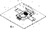
Fig. 4 shows the change scheme of a SIM card receptacle and the location of device for fastening.
Embodiment
Fig. 1 represents a security module receptacle, and it has a form that is positioned at the socket (2) on the printed circuit board (1), and printed circuit board is equivalent to for example demoder motherboard.This socket (2) is equipped with the lid (2 ') on the side of a hinge in its both sides, can insert security module (3) in each slide rail that it comprises.In the example of being set forth, the size of security module is corresponding to a SIM card, and it simultaneously is equipped with eight surface in contacts.These eight surface in contacts are towards eight contacts corresponding to socket (2), and when lid (2 ') is placed on that socket (2) is gone up and receptacle cuts out so that with security module (3) when putting into operation, eight surface of contact contact with eight contacts.
Fig. 2 shows an example according to device for fastening configuration of the present invention, and its first parts are one, and to be positioned over the label (5) and second parts that receptacle covers are transmitters, and the latter's aerial coil (8) is placed under the receptacle.In case receptacle cuts out, label (5) just is attached on the supporting cover on security module both sides on the printed circuit simultaneously, thereby receptacle is encapsulated.The label of being made by an insulating material film (5) comprises a conductive path (6) that is connected to chip piece (7).A paths that is used to form coil extends to the other end from label one end.In addition, each groove (10) that distributing on this insulation film, these grooves are formed each thin spot, and when attempt dismounting label, label is just torn to pieces easily.The conductive path that can make form of wires is included in the dielectric film of card and is connected to chip (7).It forms a quilt and demarcates antenna to service frequency, so that owing to removes the length change that is caused of tearing that label causes and just detected by the aerial coil of transmitter (8).The latter is placed on the next-door neighbour of label, is usually located under the receptacle, and it sends an electromagnetic field, is used for energy is offered the chip of label and exchanges digital signal.Coil (8) is connected to the electronic circuit of transmitter (T), and transmitter is connected to processor by an appropriate interface.The signal of transmitter coil (8) of flowing through comprises only one identification number of a chip (7) that derives from label (5).Processor is analyzed this number periodically so that it and reference number can be compared, and this reference number is registered when security module (3) is installed in receptacle.When comparative result for certainly the time, this equipment operation is normal, this means initial really that piece of installing of security module (3).
On the other hand, a mistake or impossible comparison or because the spontaneous aberration of label or because removing of making a stab has been destroyed label.In fact, can detect the label that makes new advances immediately, be different from the identification number that before is stored in the storer because of its chip comprises one.Also can both be detected and lack label or its conductive path the impaired situation of label, because no longer may compare with reference number as antenna by processor.The operation of this equipment promptly lies on the table, and thoroughly restarts it until by the maintenance service personnel a new security module being installed.
Fig. 3 represents the principle section according to the device of Fig. 2 axis A-A.The aerial coil of transmitter (8) generally all is included in the film of being made by insulating material (9), is attached to second label that is positioned at printed circuit board (1) opposite under the receptacle thereby form one.
According to another embodiment of apparatus of the present invention, second label can comprise and is similar to each groove that such being intended in first label weakens this device.This auxiliary protection measure prevents from for example label to be lifted and comes near security module by lower panel.To break the consequence of aerial coil of transmitter identical with the consequence of the conductive path of breaking first label owing to removing second label.
Can be positioned over any one side of printed circuit board according to the label of device of the present invention unimportantly.In the example of being set forth, the label that carries the transmitter aerial coil also can be positioned over the opposite that label that receptacle covered and carried chip can be positioned over printed circuit board.In this configuration, the label of closing receiver will comprise each groove that weakens usefulness.
Fig. 4 shows that the embodiment of SIM card receptacle changes scheme and the another kind of possibility of label (5) location that is used for having chip (7).Security module (3) is inserted in the socket (2) of receptacle, and label (5) is attached to the both sides of socket (2) then, not only is attached on the security module (3) but also is attached on the printed circuit board (1).A bonding agent (11) is deposited on chip on the label (7) area occupied place, and bonnet (2 ') is placed on socket (2) thereby goes up and close receptacle.Have benefited from the sticking glutinous bonding agent (11) to label of lid (2) will be torn to pieces label and damaged antenna (6) simultaneously when opening described lid (2).
According to another embodiment of the invention, the aerial coil of transmitter can be printed circuit board integration section and with another paths of circuit etched (or punch die coining) simultaneously.
Regardless of the position of this device, all will damage a label when extracting security module breaking as the lead of antenna.This defective is detected and makes the equipment anergy by the processor of this equipment.
Claims (12)
1. the device for fastening that is used for the security module connector, described connector forms one and is positioned at the part of a receptacle on the printed circuit board and is integrated into an equipment, and the function of this equipment is controlled by a processor and depend on the security module that is connected to receptacle, it is characterized in that it comprises that first parts of being made up of a label that adheres to and one are positioned near second parts the described connector, described label is adhered to like this so that encapsulate security module on printed circuit board, described label has at least one chip and one first antenna, and described second parts comprise second antenna with the transmitter of the processor communication of described equipment.
2. according to the device of claim 1, it is characterized in that this label is included in each groove of being convenient to tear to pieces described label when attempt removes it.
3. according to the device of claim 1 and 2, it is characterized in that this label by comprising that one is formed as the conductor path of antenna and an insulating material film of a chip, described antenna is connected with this chip.
4. according to the device of claim 1, it is characterized in that the antenna of transmitter is placed under the receptacle.
5. according to the device of claim 4, it is characterized in that each groove of being convenient to tear to pieces described label when attempt removes it made and be included in by the antenna of transmitter with the form of film.
6. according to the device of claim 1, it is characterized in that the antenna of transmitter is made with the form that is etched in the aerial coil on the printed circuit board.
7. according to the device of claim 1, it is characterized in that the antenna of transmitter can send an electromagnetic field, be used for energy is offered the chip of label and exchanges digital signal by described first antenna.
8. according to the device of claim 7, the signal that it is characterized in that entering the transmitter coil comprises one by only one the identification number of first antenna from chip, processor can be analyzed described number periodically, and compares with described number and when described security module is installed in the reference number of registering in the receptacle.
9. device according to Claim 8 is characterized in that the functions of the equipments that comparative result is controlled processor work.
According to Claim 8 with 9 device, it is characterized in that sure comparative result guarantees the normal function of equipment.
11., it is characterized in that the fracture of label antenna or transmitter antenna is interrupted the dialogue of chip and processor, and cause the equipment anergy according to the device of claim 1 to 9.
12. according to the device of claim 1 to 9, it is characterized in that comprising that the spontaneous change of the label of chip changes the identification number of chip, with the reference number result relatively of registration for negative, thereby cause the equipment anergy.
Applications Claiming Priority (2)
| Application Number | Priority Date | Filing Date | Title |
|---|---|---|---|
| CH21792002 | 2002-12-20 | ||
| CH20022179/02 | 2002-12-20 |
Publications (1)
| Publication Number | Publication Date |
|---|---|
| CN1729470A true CN1729470A (en) | 2006-02-01 |
Family
ID=32661017
Family Applications (1)
| Application Number | Title | Priority Date | Filing Date |
|---|---|---|---|
| CNA2003801069606A Pending CN1729470A (en) | 2002-12-20 | 2003-12-17 | Securing device for a security module connector |
Country Status (15)
| Country | Link |
|---|---|
| US (1) | US7434736B2 (en) |
| EP (1) | EP1573646B1 (en) |
| JP (1) | JP2006510983A (en) |
| KR (1) | KR20050085654A (en) |
| CN (1) | CN1729470A (en) |
| AT (1) | ATE346348T1 (en) |
| AU (1) | AU2003303276A1 (en) |
| BR (1) | BR0317604A (en) |
| CA (1) | CA2506931A1 (en) |
| DE (1) | DE60309929T2 (en) |
| ES (1) | ES2276166T3 (en) |
| MX (1) | MXPA05006454A (en) |
| PL (1) | PL376533A1 (en) |
| TW (1) | TW200414745A (en) |
| WO (1) | WO2004057519A1 (en) |
Cited By (1)
| Publication number | Priority date | Publication date | Assignee | Title |
|---|---|---|---|---|
| CN102955971A (en) * | 2011-08-22 | 2013-03-06 | 深圳市金溢科技有限公司 | Electronic tag |
Families Citing this family (28)
| Publication number | Priority date | Publication date | Assignee | Title |
|---|---|---|---|---|
| GB2397272B (en) * | 2003-01-15 | 2006-11-15 | Hewlett Packard Co | Secure physical documents and methods and apparatus for publishing and reading them |
| US7370212B2 (en) | 2003-02-25 | 2008-05-06 | Microsoft Corporation | Issuing a publisher use license off-line in a digital rights management (DRM) system |
| US20060242406A1 (en) | 2005-04-22 | 2006-10-26 | Microsoft Corporation | Protected computing environment |
| EP1617353A1 (en) * | 2004-07-13 | 2006-01-18 | Axalto SA | Mini-plug SIM card with improved positioning capability |
| US8347078B2 (en) | 2004-10-18 | 2013-01-01 | Microsoft Corporation | Device certificate individualization |
| US8336085B2 (en) * | 2004-11-15 | 2012-12-18 | Microsoft Corporation | Tuning product policy using observed evidence of customer behavior |
| US8176564B2 (en) * | 2004-11-15 | 2012-05-08 | Microsoft Corporation | Special PC mode entered upon detection of undesired state |
| US8464348B2 (en) * | 2004-11-15 | 2013-06-11 | Microsoft Corporation | Isolated computing environment anchored into CPU and motherboard |
| US20060106920A1 (en) * | 2004-11-15 | 2006-05-18 | Microsoft Corporation | Method and apparatus for dynamically activating/deactivating an operating system |
| US7979721B2 (en) * | 2004-11-15 | 2011-07-12 | Microsoft Corporation | Enhanced packaging for PC security |
| US8438645B2 (en) | 2005-04-27 | 2013-05-07 | Microsoft Corporation | Secure clock with grace periods |
| US8725646B2 (en) | 2005-04-15 | 2014-05-13 | Microsoft Corporation | Output protection levels |
| US9363481B2 (en) | 2005-04-22 | 2016-06-07 | Microsoft Technology Licensing, Llc | Protected media pipeline |
| US9436804B2 (en) | 2005-04-22 | 2016-09-06 | Microsoft Technology Licensing, Llc | Establishing a unique session key using a hardware functionality scan |
| US20060265758A1 (en) | 2005-05-20 | 2006-11-23 | Microsoft Corporation | Extensible media rights |
| US8353046B2 (en) * | 2005-06-08 | 2013-01-08 | Microsoft Corporation | System and method for delivery of a modular operating system |
| FR2889756B1 (en) * | 2005-08-11 | 2007-10-12 | Itt Mfg Enterprises Inc | FRAUD SAFETY ARRANGEMENT FOR ELECTRICAL CONNECTOR FOR CHIP CARD |
| FR2908206B1 (en) * | 2006-11-03 | 2009-02-13 | Oberthur Card Syst Sa | MICROCIRCUIT CARD WITH DEPORTED ANTENNA |
| US20080184026A1 (en) * | 2007-01-29 | 2008-07-31 | Hall Martin H | Metered Personal Computer Lifecycle |
| US7922097B2 (en) * | 2007-09-07 | 2011-04-12 | Panasonic Corporation | SIM card IC module and SIM card |
| US7980876B2 (en) * | 2008-01-17 | 2011-07-19 | Sasken Communication Technologies Limited | Lock for mobile communication equipment |
| US20100102131A1 (en) * | 2008-10-28 | 2010-04-29 | First Data Corporation | Systems and Methods for Disabling a Contactless Transaction Device |
| US9686235B2 (en) * | 2011-07-20 | 2017-06-20 | Visa International Service Association | Mobile banking system with cryptographic expansion device |
| DE102011088216A1 (en) * | 2011-12-12 | 2013-06-13 | Continental Automotive Gmbh | Engine control unit with sacrificial structure |
| WO2013166278A1 (en) | 2012-05-02 | 2013-11-07 | Visa International Service Association | Small form-factor cryptographic expansion device |
| GB2515996A (en) * | 2013-04-15 | 2015-01-14 | Johnson Electric Sa | Security wrap with tearable substrate |
| FR3027706B1 (en) * | 2014-10-28 | 2016-12-23 | Inside Secure | HYBRID ANTI-COUNTERFACON LABEL |
| FR3073307B1 (en) * | 2017-11-08 | 2021-05-28 | Oberthur Technologies | SECURITY DEVICE SUCH AS A CHIP CARD |
Family Cites Families (4)
| Publication number | Priority date | Publication date | Assignee | Title |
|---|---|---|---|---|
| TW503603B (en) * | 1999-11-23 | 2002-09-21 | Nagracard Sa | One way locking mechanism for card connector |
| DE10041868A1 (en) * | 2000-08-25 | 2002-03-07 | Amphenol Tuchel Elect | Smart card connector for smart card, SIM card with non-releasable locking of card in reader |
| JP2002073422A (en) * | 2000-09-05 | 2002-03-12 | Sharp Corp | Information processing equipment |
| JP2002248250A (en) * | 2001-02-23 | 2002-09-03 | Cyber Plaza:Kk | Monitoring electronic tag of game machine control electronic part and monitor of game machine control electronic part using monitoring electronic tag |
-
2003
- 2003-12-17 WO PCT/IB2003/006046 patent/WO2004057519A1/en active IP Right Grant
- 2003-12-17 BR BR0317604-5A patent/BR0317604A/en not_active IP Right Cessation
- 2003-12-17 JP JP2004561880A patent/JP2006510983A/en active Pending
- 2003-12-17 ES ES03813691T patent/ES2276166T3/en not_active Expired - Lifetime
- 2003-12-17 KR KR1020057010896A patent/KR20050085654A/en not_active Application Discontinuation
- 2003-12-17 DE DE60309929T patent/DE60309929T2/en not_active Expired - Lifetime
- 2003-12-17 CA CA002506931A patent/CA2506931A1/en not_active Abandoned
- 2003-12-17 US US10/535,853 patent/US7434736B2/en not_active Expired - Fee Related
- 2003-12-17 AU AU2003303276A patent/AU2003303276A1/en not_active Abandoned
- 2003-12-17 MX MXPA05006454A patent/MXPA05006454A/en active IP Right Grant
- 2003-12-17 AT AT03813691T patent/ATE346348T1/en not_active IP Right Cessation
- 2003-12-17 CN CNA2003801069606A patent/CN1729470A/en active Pending
- 2003-12-17 PL PL376533A patent/PL376533A1/en unknown
- 2003-12-17 EP EP03813691A patent/EP1573646B1/en not_active Expired - Lifetime
- 2003-12-18 TW TW092136025A patent/TW200414745A/en unknown
Cited By (2)
| Publication number | Priority date | Publication date | Assignee | Title |
|---|---|---|---|---|
| CN102955971A (en) * | 2011-08-22 | 2013-03-06 | 深圳市金溢科技有限公司 | Electronic tag |
| CN102955971B (en) * | 2011-08-22 | 2016-03-30 | 深圳市金溢科技股份有限公司 | Electronic tag |
Also Published As
| Publication number | Publication date |
|---|---|
| BR0317604A (en) | 2005-11-29 |
| TW200414745A (en) | 2004-08-01 |
| PL376533A1 (en) | 2006-01-09 |
| CA2506931A1 (en) | 2004-07-08 |
| EP1573646A1 (en) | 2005-09-14 |
| DE60309929D1 (en) | 2007-01-04 |
| ATE346348T1 (en) | 2006-12-15 |
| ES2276166T3 (en) | 2007-06-16 |
| MXPA05006454A (en) | 2005-08-19 |
| WO2004057519A1 (en) | 2004-07-08 |
| JP2006510983A (en) | 2006-03-30 |
| KR20050085654A (en) | 2005-08-29 |
| DE60309929T2 (en) | 2007-06-28 |
| AU2003303276A1 (en) | 2004-07-14 |
| EP1573646B1 (en) | 2006-11-22 |
| US20060055506A1 (en) | 2006-03-16 |
| US7434736B2 (en) | 2008-10-14 |
Similar Documents
| Publication | Publication Date | Title |
|---|---|---|
| CN1729470A (en) | Securing device for a security module connector | |
| US11263355B2 (en) | Tamper resistant module for industrial control system | |
| EP3348490B1 (en) | Sticker having ic tag, and mounting method thereof | |
| US9224280B2 (en) | Security wrap | |
| US20090212945A1 (en) | Intrusion detection systems for detecting intrusion conditions with respect to electronic component enclosures | |
| JPH10301858A (en) | Tampering prevention integrated circuit | |
| CN103582298A (en) | Security wrap | |
| US9055672B2 (en) | Device for protecting an electronic printed circuit board | |
| CN113345737B (en) | Method and apparatus for verifying and detecting circuit breaker integrity | |
| US20190097302A1 (en) | Patch antenna layer for tamper event detection | |
| US7317401B2 (en) | Method and mechanical tamper-evident case fastener | |
| US5512738A (en) | Coded seal | |
| CN101246454B (en) | Information storage equipment protecting equipment and production method for the same | |
| CN102479315A (en) | Electronic device with data protection function | |
| CN103295051A (en) | Electronic tag clamping device | |
| US20050061539A1 (en) | Mechanism for disabling an electronic assembly | |
| CN201017319Y (en) | Information memory apparatus protecting equipment | |
| KR20110016176A (en) | Self-sounding antitheft device with mgnet | |
| CN219999492U (en) | Anti-disassembly circuit board and electronic equipment | |
| JP2007090013A (en) | Unsealing monitoring system using flexible flat cable | |
| JP2001307560A (en) | Wiring member for crime prevention and electronic equipment using same | |
| JP2006075568A (en) | Unseal monitoring sensor device by flexible flat cable | |
| JP2018116354A (en) | On-vehicle equipment | |
| MXPA98001451A (en) | Circuit integrated to proof of violation | |
| JP2002134556A (en) | Semiconductor mounting structure |
Legal Events
| Date | Code | Title | Description |
|---|---|---|---|
| C06 | Publication | ||
| PB01 | Publication | ||
| C10 | Entry into substantive examination | ||
| SE01 | Entry into force of request for substantive examination | ||
| C02 | Deemed withdrawal of patent application after publication (patent law 2001) | ||
| WD01 | Invention patent application deemed withdrawn after publication |
Open date: 20060201 |