CN1656822A - Cableran networking over coaxial cables - Google Patents
Cableran networking over coaxial cables Download PDFInfo
- Publication number
- CN1656822A CN1656822A CNA028049373A CN02804937A CN1656822A CN 1656822 A CN1656822 A CN 1656822A CN A028049373 A CNA028049373 A CN A028049373A CN 02804937 A CN02804937 A CN 02804937A CN 1656822 A CN1656822 A CN 1656822A
- Authority
- CN
- China
- Prior art keywords
- coaxial cable
- coupled
- socket
- cable
- coaxial
- Prior art date
- Legal status (The legal status is an assumption and is not a legal conclusion. Google has not performed a legal analysis and makes no representation as to the accuracy of the status listed.)
- Pending
Links
Images


Classifications
-
- H—ELECTRICITY
- H04—ELECTRIC COMMUNICATION TECHNIQUE
- H04N—PICTORIAL COMMUNICATION, e.g. TELEVISION
- H04N7/00—Television systems
- H04N7/10—Adaptations for transmission by electrical cable
- H04N7/106—Adaptations for transmission by electrical cable for domestic distribution
-
- H—ELECTRICITY
- H04—ELECTRIC COMMUNICATION TECHNIQUE
- H04L—TRANSMISSION OF DIGITAL INFORMATION, e.g. TELEGRAPHIC COMMUNICATION
- H04L12/00—Data switching networks
- H04L12/28—Data switching networks characterised by path configuration, e.g. LAN [Local Area Networks] or WAN [Wide Area Networks]
-
- H—ELECTRICITY
- H04—ELECTRIC COMMUNICATION TECHNIQUE
- H04L—TRANSMISSION OF DIGITAL INFORMATION, e.g. TELEGRAPHIC COMMUNICATION
- H04L12/00—Data switching networks
- H04L12/28—Data switching networks characterised by path configuration, e.g. LAN [Local Area Networks] or WAN [Wide Area Networks]
- H04L12/2803—Home automation networks
- H04L12/2838—Distribution of signals within a home automation network, e.g. involving splitting/multiplexing signals to/from different paths
-
- H—ELECTRICITY
- H04—ELECTRIC COMMUNICATION TECHNIQUE
- H04N—PICTORIAL COMMUNICATION, e.g. TELEVISION
- H04N21/00—Selective content distribution, e.g. interactive television or video on demand [VOD]
- H04N21/20—Servers specifically adapted for the distribution of content, e.g. VOD servers; Operations thereof
- H04N21/21—Server components or server architectures
- H04N21/214—Specialised server platform, e.g. server located in an airplane, hotel, hospital
- H04N21/2143—Specialised server platform, e.g. server located in an airplane, hotel, hospital located in a single building, e.g. hotel, hospital or museum
-
- H—ELECTRICITY
- H04—ELECTRIC COMMUNICATION TECHNIQUE
- H04N—PICTORIAL COMMUNICATION, e.g. TELEVISION
- H04N7/00—Television systems
- H04N7/10—Adaptations for transmission by electrical cable
- H04N7/102—Circuits therefor, e.g. noise reducers, equalisers, amplifiers
-
- H—ELECTRICITY
- H04—ELECTRIC COMMUNICATION TECHNIQUE
- H04N—PICTORIAL COMMUNICATION, e.g. TELEVISION
- H04N7/00—Television systems
- H04N7/16—Analogue secrecy systems; Analogue subscription systems
- H04N7/162—Authorising the user terminal, e.g. by paying; Registering the use of a subscription channel, e.g. billing
- H04N7/163—Authorising the user terminal, e.g. by paying; Registering the use of a subscription channel, e.g. billing by receiver means only
-
- H—ELECTRICITY
- H04—ELECTRIC COMMUNICATION TECHNIQUE
- H04L—TRANSMISSION OF DIGITAL INFORMATION, e.g. TELEGRAPHIC COMMUNICATION
- H04L12/00—Data switching networks
- H04L12/28—Data switching networks characterised by path configuration, e.g. LAN [Local Area Networks] or WAN [Wide Area Networks]
- H04L12/2803—Home automation networks
- H04L2012/284—Home automation networks characterised by the type of medium used
- H04L2012/2841—Wireless
Landscapes
- Engineering & Computer Science (AREA)
- Signal Processing (AREA)
- Multimedia (AREA)
- Computer Networks & Wireless Communication (AREA)
- Automation & Control Theory (AREA)
- Computer Security & Cryptography (AREA)
- Small-Scale Networks (AREA)
- Near-Field Transmission Systems (AREA)
Abstract
A bi-directional coaxial cable communication network including at least one bi-directional coaxial cable extending from a remote location to a location adjacent subscriber premises and carrying traffic in opposite directions along respective frequency spectra which are separated by a separation frequency band and at least one bi-directional coaxial cable extending from the location adjacent subscriber premises to at least one outlet at the subscriber premises and carrying traffic along the separation frequency band.
Description
Invention field
The present invention relates to a kind of coaxial cable communication, relate to a kind of coaxial cable communication network and wall plug in particular.
The related application of cross-reference
The application's preference is that temporary patent application number is NO.60/268,610, and the applying date is February 13 calendar year 2001, denomination of invention is the United States Patent (USP) of " cable laying circuit "; Patent application serial number is NO.09/860,238, and the applying date is May 18 calendar year 2001, denomination of invention is the United States Patent (USP) of " with the cable system that coaxial cable laid "; Patent application serial number is NO.09/860,239, and the applying date is May 18 calendar year 2001, denomination of invention is the United States Patent (USP) of " with the cable local network that coaxial cable laid ".
Background of invention
Following United States Patent (USP) has been considered to represent the present situation of this technology:
3,836,888;4,4132,29;5,343,240;5,440,335;5,796,739;5,805,806;
5,822,677;5,822,678;5,845,190;5,896,556;5,917,624;5,963,844;
6,081,519
Summary of the invention
The present invention manage to provide a kind of improved bidirectional coaxial cabled communication network with and parts.
Therefore a kind of bidirectional coaxial cabled communication network is provided according to a preferred embodiment of the invention, this network comprise at least one extend to from afar with the portal user adjacent position on and transmit the bidirectional coaxial cable of telecommunication service in the bidirectional coaxial cable that transmits telecommunication service on the direction opposite and at least one from extending at least one socket of portal user and along the frequency band of separating with the portal user position adjacent with each frequency spectrum, wherein above-mentioned each frequency spectrum is to be separated by the frequency band of separating.
A kind of bidirectional coaxial cabled communication network also is provided according to a preferred embodiment of the invention, this network comprise at least one extend to from afar with the portal user adjacent position on and transmit the communication link of telecommunication service and at least one in the opposite direction from extending at least one socket of portal user with the portal user position adjacent and transmitting the DBS television services and second frequency band outside first frequency band transmits the bidirectional coaxial cable of other telecommunication services along first frequency band.
Socket according to one preferred embodiment of the present invention further comprises a coaxial circuit jack that links to each other with at least one coaxial cable.
This socket also comprises or also comprises non-power supply USB (USB) socket that is coupled with coaxial cable by the universal serial bus adaptor circuit in addition.
Socket according to one preferred embodiment of the present invention also comprises a non-power supply IEEE1394 sock that is coupled with coaxial cable by IEEE1394 firewall adapter circuit in addition.
Socket according to one preferred embodiment of the present invention can transmit the RF signal in addition.
Socket according to one preferred embodiment of the present invention also includes a wall plug in addition.
Network according to one preferred embodiment of the present invention also comprises an infrared transceiver that is coupled with coaxial cable in addition.
Network according to one preferred embodiment of the present invention also comprises a Bluetooth transceiving that is coupled with coaxial cable in addition.
Network according to one preferred embodiment of the present invention also comprises a wireless RF transceiver that is coupled with coaxial cable in addition.
The telecommunication service that frequency band transmitted along separating according to one preferred embodiment of the present invention comprises the VSAT telecommunication service.
Other telecommunication services according to one preferred embodiment of the present invention comprise the wideband data telecommunication service.
Also proposed a kind of bidirectional coaxial communication network according to another preferred embodiment of the invention, this network comprises a coaxial cable and an infrared transceiver that is coupled with coaxial cable.
The socket of the preferred embodiment can transmit the RF signal in addition according to the present invention.
The network of the preferred embodiment also comprises a Bluetooth transceiving that is coupled with coaxial cable in addition according to the present invention.
The network of the preferred embodiment also comprises a wireless RF transceiver that is coupled with coaxial cable in addition according to the present invention.
Another preferred embodiment according to the present invention has also proposed a kind of bidirectional coaxial communication network, and this network comprises a coaxial cable and a Bluetooth transceiving that is coupled with coaxial cable.
The socket of the preferred embodiment can transmit the RF signal in addition according to the present invention.
The network of the preferred embodiment also comprises a wireless RF transceiver that is coupled with coaxial cable in addition according to the present invention.
A preferred embodiment more according to the present invention has also proposed a kind of bidirectional coaxial communication network, and this network comprises a coaxial cable and a wireless RF transceiver that is coupled with coaxial cable.
The socket of the preferred embodiment can transmit the RF signal in addition according to the present invention.
Another preferred embodiment according to the present invention has also proposed a kind of bidirectional coaxial communication network, and this network comprises a cable and a non-power supply USB socket that is coupled with cable by the universal serial bus adaptor circuit.
Another preferred embodiment according to the present invention has also proposed a kind of bidirectional coaxial communication network, and this network comprises a cable and a non-power supply IEEE1394 sock that is coupled with cable by IEEE1394 firewall adapter circuit.
The socket of the preferred embodiment can transmit the RF signal in addition according to the present invention.
The network of the preferred embodiment also comprises an infrared transceiver that is coupled with cable in addition according to the present invention.
The network of the preferred embodiment also comprises a Bluetooth transceiving that is coupled with cable in addition according to the present invention.
The network of the preferred embodiment also comprises a wireless RF transceiver that is coupled with cable in addition according to the present invention.
Another preferred embodiment according to the present invention has also proposed a kind of multi-function jack, and this socket comprises a coax jack that is connected with coaxial cable and a non-power supply USB socket that is coupled with coaxial cable by the universal serial bus adaptor circuit.
Another preferred embodiment according to the present invention has also proposed a kind of multi-function jack, and this socket comprises a coax jack that is connected with coaxial cable and a non-power supply IEEE1394 sock that is coupled with coaxial cable by IEEE1394 firewall adapter circuit.
Another preferred embodiment according to the present invention has also proposed a kind of socket, and this socket comprises a coax jack that is connected with at least one coaxial cable and a non-power supply USB socket that is coupled with coaxial cable by the universal serial bus adaptor circuit.
Another preferred embodiment according to the present invention has also proposed a kind of socket, and this socket comprises a coax jack that is connected with at least one coaxial cable and a non-power supply IEEE1394 sock that is coupled with coaxial cable by IEEE1394 firewall adapter circuit.
Another preferred embodiment according to the present invention has also proposed a kind of socket, and this socket comprises a coax jack that is connected with coaxial cable and an infrared transceiver that is coupled with coaxial cable.
Another preferred embodiment according to the present invention has also proposed a kind of socket, and this socket comprises a coax jack that is connected with coaxial cable and a Bluetooth transceiving that is coupled with coaxial cable.
Another preferred embodiment according to the present invention has also proposed a kind of socket, and this socket comprises a coax jack that is connected with coaxial cable and a wireless RF transceiver that is coupled with coaxial cable.
The coaxial cable of the preferred embodiment also can transmit the RF signal according to the present invention.
Also proposed a kind of home network system according to a preferred embodiment of the invention, this system comprises the coaxial cable and a plurality of sockets that are coupled with coaxial cable that are used to transmit the RF telecommunication service.
According to the present invention at least one socket of the preferred embodiment further comprise one with at least one coax jack that links to each other with coaxial cable.
At least one socket also comprises a non-power supply USB socket that is coupled with coaxial cable by the universal serial bus adaptor circuit in addition.
At least one socket of the preferred embodiment also includes a wall plug according to the present invention.
The home network system of the preferred embodiment also comprises an infrared transceiver that is coupled with coaxial cable in addition according to the present invention.
The home network system of the preferred embodiment also comprises a non-power supply IEEE1394 who is coupled with coaxial cable in addition according to the present invention.
The home network system of the preferred embodiment also comprises a Bluetooth transceiving that is coupled with coaxial cable in addition according to the present invention.
The home network system of the preferred embodiment also comprises a wireless RF transceiver that is coupled with coaxial cable in addition according to the present invention.
Another preferred embodiment has also proposed a home network system in addition according to the present invention, and this system comprises the Bluetooth transceiving that coax jack that at least one links to each other with coaxial cable and at least one and coaxial cable are coupled.
Another preferred embodiment has also proposed a home network system in addition according to the present invention, and this system comprises the wireless RF transceiver that coax jack that at least one links to each other with coaxial cable and at least one and coaxial cable are coupled.
Another preferred embodiment has also proposed a home network system in addition according to the present invention, and this system comprises the infrared transceiver that coax jack that at least one links to each other with coaxial cable and at least one and coaxial cable are coupled.
The coaxial cable of the preferred embodiment also can transmit the RF signal according to the present invention.
The home network system of the preferred embodiment also comprises an infrared transceiver that is coupled with coaxial cable in addition according to the present invention.
The home network system of the preferred embodiment also comprises a Bluetooth transceiving that is coupled with coaxial cable in addition according to the present invention.
The home network system of the preferred embodiment also comprises a wireless RF transceiver that is coupled with coaxial cable in addition according to the present invention.
The home network system of the preferred embodiment also comprises a non-power supply IEEE1394 who is coupled with coaxial cable in addition according to the present invention.
Another preferred embodiment according to the present invention has proposed a kind of home network system, and this system comprises cable connector that at least one links to each other with cable and the non-power supply USB socket that at least one is coupled with cable connector by USB.
Another preferred embodiment according to the present invention has proposed a kind of home network system, and this system comprises the infrared transceiver that cable connector that at least one links to each other with cable and at least one and cable connector are coupled.
Another preferred embodiment according to the present invention has proposed a kind of home network system, and this system comprises the Bluetooth transceiving that cable connector that at least one links to each other with cable and at least one and cable connector are coupled.
Another preferred embodiment according to the present invention has proposed a kind of home network system, and this system comprises the IEEE1394 that cable connector that at least one links to each other with cable and at least one and cable connector are coupled.
Cable connector according to the present invention in the home network system of the preferred embodiment further can transmit the RF signal.
The home network system of the preferred embodiment also comprises an infrared transceiver that is coupled with cable connector in addition according to the present invention.
The home network system of the preferred embodiment also comprises a Bluetooth transceiving that is coupled with cable connector in addition according to the present invention.
The home network system of the preferred embodiment also comprises a wireless RF transceiver that is coupled with cable connector in addition according to the present invention.
The home network system of the preferred embodiment also comprises an IEEE1394 who is coupled with cable connector in addition according to the present invention.
The term that the application uses from start to finish " wireless RF " is the IEEE802.11 standard preferably, and generally includes IEEE802.11A standard and IEEE802.11B standard.
Description of drawings
In conjunction with the accompanying drawings, understanding that can be more thorough from following detailed description is also understanded the present invention, in the accompanying drawings:
Figure 1A, 1B, 1C and 1D have provided the illustrating and operating instruction according to the preferred embodiment of the invention of each embodiment of bidirectional coaxial cabled communication network and component parts thereof;
Fig. 2 has provided the simple functions block diagram of employed medium access switch in the network of Fig. 1, and wherein above-mentioned Fig. 1 constructs according to one preferred embodiment of the present invention and operates;
Fig. 3 has provided the simple functions block diagram of the medium access switch of Fig. 2;
Fig. 4 A, 4B, 4C and 4D have provided the simple flow chart that the circuit of Fig. 3 is operated;
Fig. 5 provided the multi-function jack of being constructed according to one preferred embodiment of the present invention with and the illustrating of operation;
Fig. 6 has provided the simple functions block diagram of a circuit, and this circuit has constituted the multi-function jack part in Fig. 2 preferred embodiment;
Fig. 7 has provided the rough schematic of a typical frequency spectrum, and this frequency spectrum comprises general traditional bidirectional coaxial communication bandwidth and employed typical other bandwidth in according to the preferred embodiment of the present invention.
Preferred embodiment
With reference to Figure 1A, Figure 1A provided bidirectional coaxial cabled communication network according to the preferred embodiment of the invention and component parts thereof with and the illustrating of operation.Shown in Figure 1A, a kind of bidirectional coaxial cabled communication network is provided, this network comprises that at least one is adjacent with portal user by locational shown in the Reference numeral 12 and transmit the bidirectional coaxial cable of telecommunication service in the direction opposite with each frequency spectrum from extending to such as the such remote location of headend (not providing), and wherein above-mentioned each frequency spectrum is to be separated by the frequency band of separating.
Coaxial cable 10 preferably ends at directional coupler 14 residing positions 12, and this directional coupler receives the input from medium access switch (MAS) 16, is described in detail below with reference to the preferred embodiment of 2 pairs of directional couplers of accompanying drawing.Medium access switch 16 is preferably by coaxial two-direction link 18 and link to each other with directional coupler 14 and link to each other with data source and/or data sink by suitable bi-directional data link 20, and wherein above-mentioned coaxial two-direction link 18 links to each other with suitable tap on the directional coupler 14.
Directional coupler 14 is the ZCW or the ZDC directional coupler of standard preferably, and these are by the large quantities of supplies of Blonder-Tongue of the U.S..
According to a preferred embodiment of the invention, at least one bidirectional coaxial cable 22 is to extend to from directional coupler 14 residing positions 12 at least one socket 24 that is positioned at portal user (premise) and along the frequency band that separates to transmit telecommunication service.Socket 24 is multi-function jack preferably, is described in detail below with reference to the preferred embodiment of accompanying drawing 5 and 6 pairs of sockets.
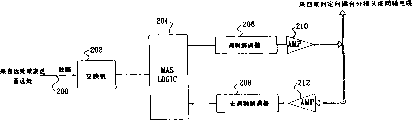
Fig. 7 has provided the frequency spectrum of typical bidirectional coaxial cable communication.Bandwidth at 5-42MHz and 55-860MHz is respectively applied for updrift side and the downstream direction that conventional coaxial cable is communicated by letter usually as can be seen.According to a preferred embodiment of the invention, another upstream bandwidth 26 and another downstream bandwidth 28 respectively in the future the information of automodulation demodulator 206 and amplifier 210 be sent to amplifier 212 and remove modulator-demodulator 208 (Fig. 2).In addition or upstream bandwidth and downstream bandwidth also can be positioned at the above zone of 0-5MHz and 860MHz.Be understandable that network system also can operate in the used frequency band 5-150MHz of tradition.
According to a preferred embodiment of the invention, the network in the portal user provides a home network system, and wherein at least one coaxial cable 22 is sent to the RF telecommunication service such as on the such a plurality of sockets that are coupled with coaxial cable 22 of socket 24.
With reference now to accompanying drawing 1B,, accompanying drawing 1B has provided illustrating of bidirectional coaxial cabled communication network and component parts thereof and the illustrating of operation of another preferred embodiment according to the present invention.Shown in Figure 1B, a kind of bidirectional coaxial cabled communication network is provided, this network comprises that at least one receives reflector 31 from satellite broadcasting and extends to adjacently with portal user by locational coaxial cable 30 shown in the Reference numeral 32, and wherein above-mentioned satellite broadcasting receives the part that reflector 31 has preferably constituted the DBS broadcasting-satellite system.
According to a preferred embodiment of the invention, at least one bidirectional coaxial cable 42 is to extend to from directional coupler 34 residing positions 32 at least one socket 44 that is positioned at portal user and along the frequency band that separates to transmit telecommunication service.Socket 44 is multi-function jack preferably, is described in detail below with reference to accompanying drawing 5 and 6 preferred embodiments to this socket.
According to a preferred embodiment of the invention, the network in the portal user provides a home network system, and wherein at least one coaxial cable 42 is sent to the RF telecommunication service such as on the such a plurality of sockets that are coupled with coaxial cable 42 of socket 44.
With reference now to accompanying drawing 1C,, accompanying drawing 1C has provided illustrating of bidirectional coaxial cabled communication network and component parts thereof and the illustrating of operation of another preferred embodiment according to the present invention.Shown in Fig. 1 C, a kind of bidirectional coaxial cabled communication network is provided, and this network comprises that at least one is adjacent with portal user by locational bi-directional data cable 50 shown in the Reference numeral 52 from extending to such as VSAT reflector, LMDS CPE or the such wireless data link terminal 51 of arbitrary other appropriate terminal.
According to a preferred embodiment of the invention, the network in the portal user provides a home network system, and wherein at least one coaxial cable 62 is sent to the RF telecommunication service such as on the such a plurality of sockets that are coupled with coaxial cable 62 of socket 64.
With reference now to accompanying drawing 1D,, accompanying drawing 1D has provided illustrating of bidirectional coaxial cabled communication network and component parts thereof and the illustrating of operation of another preferred embodiment according to the present invention.Shown in Fig. 1 D, a kind of bidirectional coaxial cabled communication network is provided, and this network comprises that at least one is adjacent with portal user by locational bi-directional data cable 70 shown in the Reference numeral 72 from extending to such as Fiber To The Curb (FTTC) terminal, Digital Subscriber Loop technology (DSL) CPE, E1/T1 modulator-demodulator or the such data link terminal 71 of cable modem.
Cable 70 preferably ends at medium access switch (MAS) 76 residing positions 72, is described in detail below with reference to the preferred embodiment of 2 pairs of medium access switches 76 of accompanying drawing.Medium access switch 76 preferably links to each other with at least one bidirectional coaxial cable 82, and this bidirectional coaxial cable 82 extends at least one socket 84 that is positioned at portal user.Socket 84 is multi-function jack preferably, is described in detail below with reference to accompanying drawing 5 and 6 preferred embodiments to this socket.
According to a preferred embodiment of the invention, the network in the portal user provides a home network system, and wherein at least one coaxial cable 82 is sent to the RF telecommunication service such as on the such a plurality of sockets that are coupled with coaxial cable 82 of socket 84.
With reference to the accompanying drawings 2, accompanying drawing 2 has provided the simple functions block diagram of employed medium access switch in the network of Figure 1A, 1B, 1C and 1D, and wherein above-mentioned Fig. 1 constructs according to one preferred embodiment of the present invention and operates.As shown in Figure 2, from extending to such as SUPERSTACK 3R hub or such transducer or hub or the router two 02 of transducer such as headend or the such remote location of ISP transducer, these are by the large quantities of supplies of California, USA Santa Clara company of 3Com such as the such data link 200 of Ethernet or ATM data link.To offer MAS logic module 204 by the received data of data link by transducer or router, this MAS logic module 204 is extracted data from input traffic.Preferred embodiment below with reference to 3 pairs of MAS logic modules 204 of accompanying drawing is described in detail.
Below with reference to accompanying drawing 3, Fig. 3 has provided the simple functions block diagram of MAS logic module 204.As shown in Figure 3, MAS logic module 204 comprises the bridger logical circuit 300 that is coupled with network management logical circuit 302 and RF management logic circuit.Usually analyze from switch 202 (Fig. 2) by bridger logical circuit 300 and receive the data of coming.The partial data relevant with network management offered network management logical circuit 302, and offer RF management logic circuit 304 managing relevant partial data with RF.Data from bridger logic module 300 output to modulator-demodulator 206 (Fig. 2) by RF driver 306.
Similarly, analyze from going modulator-demodulator 208 (Fig. 2) to receive the data of coming by bridger logical circuit 300 usually.The partial data relevant with network management offered network management logical circuit 302, and offer RF management logic circuit 304 managing relevant partial data with RF.To output to switch 202 (Fig. 2) from the data of bridger logic module 300.
Network management logical circuit 302 is the state reported of processing controls and system preferably, and utilizes the snmp protocol of standard to operate usually.Circuit 302 according to as described below to such as decoding from switch 202 received packets of information and moving according to the information that is included in wherein.Network management logical circuit 302 also is used for sink information and various sockets is configured.
Come the operation of MAS logical circuit 204 is described in detail below with reference to the flow chart shown in Fig. 4 A-4D.Shown in Fig. 4 A, when bridger logical circuit 300 receives packets of information from switch 202 (Fig. 2), the destination address of analysis package (DA).If destination address is a broadcast address, then packets of information is offered network management logic module 302 and RF driver 306 (Fig. 3).
If destination address is the bridger address, then packets of information is only offered network management logic module 302 (Fig. 3).
If when destination address was other addresses except bridger address and broadcast address, then just packets of information only offered RF driver 306 (Fig. 3).
Shown in Fig. 4 B, when bridger logical circuit 300 receives packets of information from network management logic module 302 (Fig. 3), the destination address of analysis package (DA).If destination address is a broadcast address, then packets of information is offered switch 202 (Fig. 2) and RF driver 306 (Fig. 3).
If destination address is the socket address, then packets of information is only offered RF driver 306.
If destination address is neither broadcast address neither the socket address time, then only offers switch 202 with packets of information.
Shown in Fig. 4 C, when bridger logical circuit 300 receives packets of information from RF management logic 304 (Fig. 3), then packets of information is only offered RF driver 306.
Shown in Fig. 4 D,, then these data are sent to RF management logic 304 (Fig. 3) when bridger logical circuit 300 receives when having RF control packet header from the data of RF driver 306 and this data.Otherwise, from received extracting data packets of information, and the destination address of analysis package (DA).If destination address is a broadcast address, then packets of information is offered network management logical circuit 302 (Fig. 3) and RF driver 306.
If destination address is the bridger address, then packets of information is only offered network management logical circuit 302.
If destination address is the socket address, then packets of information is only offered RF driver 306.
If destination address is neither broadcast address neither the socket address time, then only offers switch 202 with packets of information.
With reference now to accompanying drawing 5,, Fig. 5 provided according to one preferred embodiment of the present invention and in Figure 1A-1D employed multi-function jack 520 structure with and the illustrating of operation.Preferably, socket 520 links to each other with coaxial cable 522, and coaxial cable 522 is sealed within the walls or extends along its skirting board.Circuit 523 in the socket links to each other coaxial cable 522 with one or more connectors or interface, Fig. 6 has provided a preferred embodiment of this circuit 523, and it generally includes a TV coax jack 524, a blue tooth interface 525, a wireless RF interface 526, a USB (USB (universal serial bus)) or USB/2 connector 527, an IEEE1394 fire compartment wall 529 and such as propagating the such IR interface 528 of IR interface.
Below with reference to accompanying drawing 6, Fig. 6 has provided the simple functions block diagram (Fig. 5) of the preferred embodiment of socket circuit 523.Directional coupler 600 preferably has the OUT port and the IN port that links to each other with TV coax jack 524 that are coupled with coaxial cable 522 (Fig. 5).Directional coupler 600 is the ZCW or the ZDC directional coupler of standard preferably, and this is by the large quantities of supplies of Blonder-Tongue of the U.S..
The TAP port of directional coupler 600 is divided into two and parallel being coupled with pair of bandpass 602 and 604. Band pass filter 602 and 604 is usually all on the direction of 5-150MHz.Offer modulator-demodulator 610 and offer data converter 612 thus by the output with filter 602 of automatic gain control (AGC) circuit 606 and A-D inverter 608, this data converter is encapsulated in output in the packets of information that is suitable for USB, IR, bluetooth, IEEE1394 fire compartment wall and wireless RF with suitable form.Transmit suitable packets of information by blue tooth interface 525, wireless RF interface 526, USB or USB/2 connector 527, IEEE1394 fire compartment wall 529 and interface 528 then.
After this to unpacking and provide it to modulator-demodulator 614 by blue tooth interface 525, wireless RF interface 526, USB or USB/2 connector 527, IEEE1394 fire compartment wall 529 and the 528 received inputs of IR interface, and provide it to the TAP port of directional coupler 600 thus by D-A transducer 616, amplifier 618 and band pass filter 604 by data converter 612.
The present invention is not limited to specific accompanying drawing and foregoing description to those skilled in the art.Scope more precisely of the present invention comprises the variations and modifications to non-prior art that above-mentioned various combination of features and distortion and those of ordinary skills have been done under the situation of having read specification.
Claims (94)
1, a kind of bidirectional coaxial cabled communication network, this network comprises:
At least one extend to from afar with the portal user adjacent position on and on the direction opposite, transmit the bidirectional coaxial cable of telecommunication service with each frequency spectrum, wherein above-mentioned each frequency spectrum is to be separated by the frequency band of separating; And
At least one extend to from the described position adjacent with portal user at least one socket that is positioned at described portal user and transmit the bidirectional coaxial cable of telecommunication service along the frequency band of separating.
2, according to the bidirectional coaxial cabled communication network of claim 1, wherein said socket comprises: a coaxial cable jack, this jack links to each other with at least one coaxial cable.
3, according to the bidirectional coaxial cabled communication network of claim 1 or 2, wherein said socket comprises:
One non-power supply USB (USB) socket, this socket is by a universal serial bus adaptor
Circuit and described coaxial cable are coupled.
4, according to the bidirectional coaxial cabled communication network of the arbitrary claim in front, wherein said socket comprises:
One non-power supply IEEE1394 socket, this socket is coupled by IEEE 1394 adapter circuits and described coaxial cable.
5, according to the bidirectional coaxial cabled communication network of the arbitrary claim in front, wherein said coaxial cable can transmit the RF signal.
6, according to the bidirectional coaxial cabled communication network of the arbitrary claim in front, wherein said socket comprises
One wall plug.
7, according to the bidirectional coaxial cabled communication network of the arbitrary claim in front, this network also comprises: an infrared transceiver that is coupled with described coaxial cable.
8, according to the bidirectional coaxial cabled communication network of the arbitrary claim in front, this network also comprises:
A Bluetooth transceiving that is coupled with described coaxial cable.
9, according to the bidirectional coaxial cabled communication network of the arbitrary claim in front, this network also comprises:
A wireless RF transceiver that is coupled with coaxial cable.
10, according to the bidirectional coaxial cabled communication network of the arbitrary claim in front, wherein comprise the VSAT telecommunication service along the telecommunication service that frequency band transmitted that separates.
11, a kind of bidirectional coaxial cabled communication network, this network comprises:
At least one extend to from afar with the portal user adjacent position on and transmit the communication link of telecommunication service in the opposite direction; And
At least one from the portal user adjacent position extend at least one socket that is positioned at portal user and transmit the DBS television services and second frequency band outside first frequency band transmits the bidirectional coaxial cable of other telecommunication services along first frequency band.
12, according to the bidirectional coaxial cabled communication network of claim 11, wherein said other telecommunication services comprise the broadcast data telecommunication service.
13, according to the bidirectional coaxial cabled communication network of claim 11 or 12, wherein said socket also comprises:
A coaxial cable that links to each other with at least one coaxial cable.
14, according to the bidirectional coaxial cabled communication network of claim 11 to 13, wherein said socket also comprises:
One non-power supply USB socket, this socket is coupled by a universal serial bus adaptor circuit and described coaxial cable.
15, according to the bidirectional coaxial cabled communication network of claim 11 to 14, wherein said described socket also comprises:
One non-power supply IEEE 1394 sockets, this socket is coupled by IEEE 1394 adapter circuits and described coaxial cable.
16, according to the bidirectional coaxial cabled communication network of arbitrary claim of claim 11 to 15, wherein said coaxial cable can transmit the RF signal.
17, according to the bidirectional coaxial cabled communication network of arbitrary claim of claim 11 to 16, wherein said socket comprises a wall plug.
18, according to the bidirectional coaxial cabled communication network of arbitrary claim of claim 11 to 17, this network also comprises:
An infrared transceiver that is coupled with described coaxial cable.
19, according to the bidirectional coaxial cabled communication network of arbitrary claim of claim 11 to 18, this network also comprises:
A Bluetooth transceiving that is coupled with described coaxial cable.
20, according to the bidirectional coaxial cabled communication network of arbitrary claim of claim 11 to 19, this network
Also comprise:
A wireless RF transceiver that is coupled with coaxial cable.
21, a kind of bidirectional coaxial cabled communication network, this network comprises:
One coaxial cable; And
An infrared transceiver that is coupled with coaxial cable.
22, according to the bidirectional coaxial cabled communication network of claim 21, wherein said coaxial cable also can transmit the RF signal.
23, according to the bidirectional coaxial cabled communication network of claim 21 or 22, this network also comprises: a Bluetooth transceiving that is coupled with described coaxial cable.
24, according to the bidirectional coaxial cabled communication network of arbitrary claim of claim 21 to 23, this network
Also comprise:
A wireless RF transceiver that is coupled with described coaxial cable.
25, a kind of bidirectional coaxial cabled communication network, this network comprises:
A coaxial cable; And
A Bluetooth transceiving that is coupled with described coaxial cable.
26, according to the bidirectional coaxial communication network of claim 25, wherein said coaxial cable transmits the RF signal.
27, according to the bidirectional coaxial communication network of claim 25 or 26, this network also comprises: a wireless RF transceiver that is coupled with described coaxial cable.
28, a kind of bidirectional coaxial communication network, this network comprises:
A coaxial cable; And
A wireless RF transceiver that is coupled with described coaxial cable.
29, according to the bidirectional coaxial communication network of claim 28, wherein said coaxial cable transmits the RF signal.
30, a kind of bidirectional coaxial communication network, this network comprises:
One cable; And
A non-power supply USB socket, this socket is coupled by universal serial bus adaptor circuit and described cable.
31, according to the bidirectional coaxial communication network of claim 30, wherein said coaxial cable transmits the RF signal.
32, according to the bidirectional coaxial communication network of claim 30 or 31, this network also comprises: an infrared transceiver that is coupled with described cable.
33, as any bidirectional coaxial communication network among the claim 30-32, further comprise:
Non-power supply IEEE 1394 sockets, this socket is coupled by IEEE 1394 adapter circuits and described cable.
34, according to the bidirectional coaxial cable system of arbitrary claim of claim 30 to 33, this network also comprises:
A Bluetooth transceiving that is coupled with described cable.
35, according to the bidirectional coaxial cable system of arbitrary claim of claim 30 to 34, this network also comprises:
A wireless RF transceiver that is coupled with described cable.
36, a kind of multi-function jack, this socket comprises:
A coax jack, this jack links to each other with coaxial cable; And
A non-power supply USB socket, this socket is coupled by universal serial bus adaptor circuit and described coaxial cable.
37, according to the multi-function jack of claim 36, wherein said coaxial cable transmits the RF signal.
38, a kind of socket, this socket comprises:
A coax jack, this jack links to each other with at least one coaxial cable; And
A USB socket, this socket is coupled by universal serial bus adaptor circuit and described coaxial cable.
39, according to the socket of claim 38, wherein said coaxial cable transmits the RF signal.
40, a kind of socket, this socket comprises:
A coax jack, this jack and coaxial cable are mutually; And
Non-power supply IEEE 1394 sockets, this socket is coupled by IEEE 1394 adapter circuits and described coaxial cable.
41, according to the socket of claim 38, wherein said coaxial cable transmits the RF signal.
42, a kind of socket, this socket comprises:
A coax jack, this jack and coaxial cable are mutually; And
An infrared transceiver that is coupled with described coaxial cable.
43, according to the socket of claim 42, wherein said coaxial cable transmits the RF signal.
44, a kind of socket, this socket comprises:
A coax jack, this jack and coaxial cable are mutually; And
A Bluetooth transceiving that is coupled with described coaxial cable.
45, according to the socket of claim 44, wherein said coaxial cable transmits the RF signal.
46, a kind of socket, this socket comprises:
A coax jack, this jack and coaxial cable are mutually; And
A wireless RF transceiver that is coupled with described coaxial cable.
47, according to the socket of claim 46, wherein said coaxial cable transmits the RF signal.
48, a kind of home network system, this system comprises:
Be used to transmit the coaxial cable of RF telecommunication service; And
The a plurality of sockets that are coupled with described coaxial cable.
49, according to the home network system of claim 48, wherein at least one described socket comprises:
One with at least one coax jack that links to each other with coaxial cable.
50, according to the home network system of claim 48, wherein at least one described socket comprises:
A non-power supply USB socket, this socket is coupled by universal serial bus adaptor circuit and described coaxial cable.
51, according to the home network system of claim 49, wherein at least one described socket comprises:
A non-power supply USB socket, this socket is coupled by universal serial bus adaptor circuit and described coaxial cable.
52, according to the home network system of arbitrary claim of claim 48 to 51, wherein at least one socket includes a wall plug.
53, according to the home network system of arbitrary claim of claim 48 to 52, this system also comprises:
An infrared transceiver that is coupled with described coaxial cable.
54, according to the home network system of arbitrary claim of claim 48 to 52, this system also comprises:
An infrared transceiver that is coupled with described coaxial cable.
55, according to the home network system of arbitrary claim of claim 48 to 54, this system also comprises:
A non-power supply IEEE1394 who is coupled with described coaxial cable.
56, according to the home network system of arbitrary claim of claim 48 to 55, this system also comprises:
A Bluetooth transceiving that is coupled with described coaxial cable.
57, according to the home network system of arbitrary claim of claim 48 to 55, this system also comprises:
A Bluetooth transceiving that is coupled with described coaxial cable.
58, according to the home network system of arbitrary claim of claim 48 to 57, this system also comprises:
A wireless RF transceiver that is coupled with described coaxial cable.
59, according to the home network system of arbitrary claim of claim 48 to 57, this system also comprises:
A RF transceiver that is coupled with described coaxial cable.
60, according to the home network system of arbitrary claim of claim 48 to 59, this system also comprises:
IEEE 1394 transceivers that are coupled with described coaxial cable.
61, a kind of home network system, this system comprises:
The coax jack that at least one links to each other with coaxial cable; And
The infrared transceiver that at least one and described coaxial cable are coupled.
62, according to the home network system of claim 61, wherein said coaxial cable transmits the RF signal.
63, according to the home network system of claim 61 or 62, this network also comprises:
A Bluetooth transceiving that is coupled with described coaxial cable.
64, according to the home network system of arbitrary claim of claim 61 to 63, this system also comprises:
A wireless RF transceiver that is coupled with described coaxial cable.
65, according to the home network system of arbitrary claim of claim 61 to 64, this system also comprises:
IEEE 1394 transceivers that are coupled with described coaxial cable.
66, a kind of home network system, this system comprises:
The coax jack that at least one links to each other with coaxial cable; And
The Bluetooth transceiving that at least one and described coaxial cable are coupled.
67, according to the home network system of claim 66, wherein said coaxial cable transmits the RF signal.
68, according to the home network system of claim 66 or 67, this network also comprises:
An infrared transceiver that is coupled with described coaxial cable.
69, according to the home network system of arbitrary claim of claim 66 to 68, this system also comprises:
A wireless RF transceiver that is coupled with described coaxial cable.
70, according to the home network system of arbitrary claim of claim 66 to 69, this system also comprises:
IEEE 1394 transceivers that are coupled with described coaxial cable.
71, a kind of home network system, this system comprises:
The coax jack that at least one links to each other with coaxial cable; And
The wireless RF transceiver that at least one and described coaxial cable are coupled.
72, according to the home network system of claim 71, wherein said coaxial cable transmits the RF signal.
73, according to the home network system of claim 71 or 72, this network also comprises:
An infrared transceiver that is coupled with described coaxial cable.
74, according to the home network system of arbitrary claim of claim 71 to 73, this system also comprises:
A Bluetooth transceiving that is coupled with described coaxial cable.
75, according to the home network system of arbitrary claim of claim 71 to 73, this system also comprises:
IEEE 1394 transceivers that are coupled with described coaxial cable.
76, a kind of home network system, this system comprises:
The cable connector that at least one links to each other with cable; And
At least one non-power supply USB socket, this socket is coupled by universal serial bus adaptor circuit and cable connector.
77, according to the home network system of claim 76, wherein said cable connector transmits the RF signal.
78, according to the home network system of claim 76 or 77, this network also comprises:
An infrared transceiver that is coupled with described cable connector.
79, according to the home network system of arbitrary claim of claim 76 to 78, this system also comprises:
A Bluetooth transceiving that is coupled with described cable connector.
80, according to the home network system of arbitrary claim of claim 76 to 79, this system also comprises:
A wireless RF transceiver that is coupled with described cable connector.
81, according to the home network system of arbitrary claim of claim 76 to 80, this system also comprises:
IEEE 1394 transceivers that are coupled with described cable connector.
82, a kind of home network system, this system comprises:
The cable connector that at least one links to each other with cable; And
The infrared transceiver that at least one and described cable connector are coupled.
83,2 home network system according to Claim 8, wherein said cable connector transmits the RF signal.
84,2 or 83 home network system according to Claim 8, this network also comprises:
A Bluetooth transceiving that is coupled with described cable connector.
85, the home network system of arbitrary claim of 2 to 84 according to Claim 8, this system also comprises:
A wireless RF transceiver that is coupled with described cable connector.
86, a kind of home network system, this system comprises:
The cable connector that at least one links to each other with cable; And
The Bluetooth transceiving that at least one and described cable connector are coupled.
87,6 home network system according to Claim 8, wherein said cable connector transmits the RF signal.
88,6 or 87 home network system according to Claim 8, this network also comprises:
An infrared transceiver that is coupled with described cable connector.
89, the home network system of arbitrary claim of 6 to 88 according to Claim 8, this system also comprises:
A wireless RF transceiver that is coupled with described cable connector.
90, a kind of home network system, this system comprises:
The cable connector that at least one links to each other with cable; And
The IEEE 1394 that at least one and described cable connector are coupled.
91, according to the home network system of claim 90, wherein said cable connector transmits the RF signal.
92, according to the home network system of claim 90 or 91, this network also comprises:
An infrared transceiver that is coupled with described cable connector.
93, according to the home network system of arbitrary claim of claim 90 to 92, this system also comprises:
A wireless RF transceiver that is coupled with described cable connector.
94, according to the home network system of arbitrary claim of claim 90 to 93, this system also comprises:
A Bluetooth transceiving that is coupled with described cable connector.
Applications Claiming Priority (6)
| Application Number | Priority Date | Filing Date | Title |
|---|---|---|---|
| US26861001P | 2001-02-13 | 2001-02-13 | |
| US60/268,610 | 2001-02-13 | ||
| US09/860,239 US20050204066A9 (en) | 2001-02-13 | 2001-05-18 | Cableran home networking over coaxial cables |
| US09/860,239 | 2001-05-18 | ||
| US09/860,238 US20020194605A1 (en) | 2001-05-18 | 2001-05-18 | Cableran networking over coaxial cables |
| US09/860,238 | 2001-05-18 |
Publications (1)
| Publication Number | Publication Date |
|---|---|
| CN1656822A true CN1656822A (en) | 2005-08-17 |
Family
ID=27402095
Family Applications (1)
| Application Number | Title | Priority Date | Filing Date |
|---|---|---|---|
| CNA028049373A Pending CN1656822A (en) | 2001-02-13 | 2002-02-06 | Cableran networking over coaxial cables |
Country Status (7)
| Country | Link |
|---|---|
| EP (1) | EP1413147A4 (en) |
| JP (1) | JP2004525557A (en) |
| KR (1) | KR20030097802A (en) |
| CN (1) | CN1656822A (en) |
| AU (1) | AU2002230072A1 (en) |
| IL (1) | IL157265A0 (en) |
| WO (1) | WO2002065229A2 (en) |
Cited By (1)
| Publication number | Priority date | Publication date | Assignee | Title |
|---|---|---|---|---|
| CN111614849A (en) * | 2020-04-15 | 2020-09-01 | 北京瀚诺半导体科技有限公司 | Indoor communication system based on coaxial cable |
Families Citing this family (16)
| Publication number | Priority date | Publication date | Assignee | Title |
|---|---|---|---|---|
| DE19907229C2 (en) | 1999-02-19 | 2003-06-12 | Beru Ag | glow plug |
| IL152824A (en) | 2002-11-13 | 2012-05-31 | Mosaid Technologies Inc | Addressable outlet and a network using same |
| IL154921A (en) | 2003-03-13 | 2011-02-28 | Mosaid Technologies Inc | Telephone system having multiple distinct sources and accessories therefor |
| IL160417A (en) | 2004-02-16 | 2011-04-28 | Mosaid Technologies Inc | Outlet add-on module |
| IL161869A (en) | 2004-05-06 | 2014-05-28 | Serconet Ltd | System and method for carrying a wireless based signal over wiring |
| IL166445A (en) | 2005-01-23 | 2011-07-31 | Mosaid Technologies Inc | Device and method for estimating the termination to a wired transmission-line based on determination of characteristic impedance |
| US7813451B2 (en) | 2006-01-11 | 2010-10-12 | Mobileaccess Networks Ltd. | Apparatus and method for frequency shifting of a wireless signal and systems using frequency shifting |
| US8594133B2 (en) | 2007-10-22 | 2013-11-26 | Corning Mobileaccess Ltd. | Communication system using low bandwidth wires |
| US8175649B2 (en) | 2008-06-20 | 2012-05-08 | Corning Mobileaccess Ltd | Method and system for real time control of an active antenna over a distributed antenna system |
| US8325691B2 (en) | 2008-09-26 | 2012-12-04 | Optical Cable Corporation | Method and apparatus for providing wireless communications within a building |
| EP2399141A4 (en) | 2009-02-08 | 2012-08-01 | Corning Mobileaccess Ltd | Communication system using cables carrying ethernet signals |
| US8798529B2 (en) | 2010-05-05 | 2014-08-05 | Optical Cable Corporation | Method and apparatus for enhancing wireless communications to and from the inside of a building |
| EP2829152A2 (en) | 2012-03-23 | 2015-01-28 | Corning Optical Communications Wireless Ltd. | Radio-frequency integrated circuit (rfic) chip(s) for providing distributed antenna system functionalities, and related components, systems, and methods |
| RU2014144141A (en) * | 2012-04-24 | 2016-06-10 | Вебтьюнер, Корпорейшен | TV ADAPTER |
| JP6430165B2 (en) * | 2014-07-30 | 2018-11-28 | Dxアンテナ株式会社 | Wall connector |
| US9184960B1 (en) | 2014-09-25 | 2015-11-10 | Corning Optical Communications Wireless Ltd | Frequency shifting a communications signal(s) in a multi-frequency distributed antenna system (DAS) to avoid or reduce frequency interference |
Family Cites Families (10)
| Publication number | Priority date | Publication date | Assignee | Title |
|---|---|---|---|---|
| US5802173A (en) * | 1991-01-15 | 1998-09-01 | Rogers Cable Systems Limited | Radiotelephony system |
| US5421030A (en) * | 1991-09-17 | 1995-05-30 | Com21, Inc. | Communications system and method for bi-directional communications between an upstream control facility and downstream user terminals |
| US6009465A (en) * | 1996-01-22 | 1999-12-28 | Svi Systems, Inc. | Entertainment and information systems and related management networks for a remote video delivery system |
| JP3697317B2 (en) * | 1996-05-28 | 2005-09-21 | 株式会社東芝 | Communication device |
| US6167120A (en) * | 1996-11-06 | 2000-12-26 | Lextron Systems, Inc. | Apparatus and methods for home networking |
| DE19721532C2 (en) * | 1997-05-22 | 2002-09-19 | Christian Schwaiger Gmbh & Co | Combination antenna socket for installation in a standardized surface or flush-mounted box |
| US6081533A (en) * | 1997-06-25 | 2000-06-27 | Com21, Inc. | Method and apparatus for an application interface module in a subscriber terminal unit |
| US6219409B1 (en) * | 1998-02-27 | 2001-04-17 | Sharegate, Inc. | Premises gateway and premises network interfaces for accessing subscriber premises equipment and communication networks using ring suppression |
| US6243413B1 (en) * | 1998-04-03 | 2001-06-05 | International Business Machines Corporation | Modular home-networking communication system and method using disparate communication channels |
| US6069588A (en) * | 1999-02-11 | 2000-05-30 | Ericsson Inc. | Systems and methods for coaxially coupling an antenna to a radiotelephone through a window and amplifying signals adjacent and inside the window |
-
2002
- 2002-02-06 IL IL15726502A patent/IL157265A0/en unknown
- 2002-02-06 CN CNA028049373A patent/CN1656822A/en active Pending
- 2002-02-06 AU AU2002230072A patent/AU2002230072A1/en not_active Abandoned
- 2002-02-06 JP JP2002564685A patent/JP2004525557A/en active Pending
- 2002-02-06 KR KR10-2003-7010508A patent/KR20030097802A/en not_active Application Discontinuation
- 2002-02-06 EP EP02711192A patent/EP1413147A4/en not_active Withdrawn
- 2002-02-06 WO PCT/IL2002/000102 patent/WO2002065229A2/en not_active Application Discontinuation
Cited By (1)
| Publication number | Priority date | Publication date | Assignee | Title |
|---|---|---|---|---|
| CN111614849A (en) * | 2020-04-15 | 2020-09-01 | 北京瀚诺半导体科技有限公司 | Indoor communication system based on coaxial cable |
Also Published As
| Publication number | Publication date |
|---|---|
| WO2002065229A2 (en) | 2002-08-22 |
| KR20030097802A (en) | 2003-12-31 |
| IL157265A0 (en) | 2004-02-19 |
| WO2002065229A3 (en) | 2003-02-20 |
| JP2004525557A (en) | 2004-08-19 |
| EP1413147A4 (en) | 2007-03-14 |
| EP1413147A2 (en) | 2004-04-28 |
| AU2002230072A1 (en) | 2002-08-28 |
Similar Documents
| Publication | Publication Date | Title |
|---|---|---|
| CN1656822A (en) | Cableran networking over coaxial cables | |
| CN1186903C (en) | Dynamic network device for one-way adapter | |
| US20020194605A1 (en) | Cableran networking over coaxial cables | |
| US20050204066A9 (en) | Cableran home networking over coaxial cables | |
| CN1197323C (en) | Application operation in bi-directional communication system compatible with internet | |
| CN1925656A (en) | Multimode communication IC and its information interacting method | |
| CN1430848A (en) | Network combining wired and non-wired segments | |
| CN1951097A (en) | System and method for carrying a wireless based signal over wiring | |
| CN1334664A (en) | Radio communication apparatus | |
| CN1878133A (en) | Dynamic VLAN ID assignment and packet transfer apparatus | |
| CN1871750A (en) | Modular outlet | |
| CN1764138A (en) | The communication means of radio network device and this radio network device of use | |
| CN100345421C (en) | Broadband access system and access method implemented on cable TV network | |
| CN1319308A (en) | Method and apparatus for data communication | |
| JP2018533241A (en) | Method and apparatus for controlling a filter circuit in a signal communication device | |
| CN1777150A (en) | Method for realizing user-isolated virtual LAN and its network device | |
| CN1458753A (en) | Up-stream optical transmission system for cabled TV | |
| CN1852234A (en) | Method for transmitting message | |
| CN1787519A (en) | Apparatus for realizing data transmitting and data access system thereof | |
| CN1130869C (en) | Method for determing swtiching on frequency band and first and last end of realized said method | |
| CN1805401A (en) | Network relay apparatus and network relay method | |
| CN1578437A (en) | Video receiving tuner | |
| CN1744701A (en) | System for implementing data communication based on cable television network | |
| CN102437940B (en) | Photoelectric conversion access device | |
| KR101034931B1 (en) | Wireless outdoor access point device and wifi service system using hybrid fiber and coaxial network |
Legal Events
| Date | Code | Title | Description |
|---|---|---|---|
| C06 | Publication | ||
| PB01 | Publication | ||
| C10 | Entry into substantive examination | ||
| SE01 | Entry into force of request for substantive examination | ||
| C02 | Deemed withdrawal of patent application after publication (patent law 2001) | ||
| WD01 | Invention patent application deemed withdrawn after publication |