CN1553850B - Post mold cooling method and device for molded article neck finishes - Google Patents
Post mold cooling method and device for molded article neck finishes Download PDFInfo
- Publication number
- CN1553850B CN1553850B CN02817708.8A CN02817708A CN1553850B CN 1553850 B CN1553850 B CN 1553850B CN 02817708 A CN02817708 A CN 02817708A CN 1553850 B CN1553850 B CN 1553850B
- Authority
- CN
- China
- Prior art keywords
- mentioned
- prefabricated component
- cooling
- surface area
- exposed surface
- Prior art date
- Legal status (The legal status is an assumption and is not a legal conclusion. Google has not performed a legal analysis and makes no representation as to the accuracy of the status listed.)
- Expired - Fee Related
Links
Images


Classifications
-
- B—PERFORMING OPERATIONS; TRANSPORTING
- B29—WORKING OF PLASTICS; WORKING OF SUBSTANCES IN A PLASTIC STATE IN GENERAL
- B29C—SHAPING OR JOINING OF PLASTICS; SHAPING OF MATERIAL IN A PLASTIC STATE, NOT OTHERWISE PROVIDED FOR; AFTER-TREATMENT OF THE SHAPED PRODUCTS, e.g. REPAIRING
- B29C45/00—Injection moulding, i.e. forcing the required volume of moulding material through a nozzle into a closed mould; Apparatus therefor
- B29C45/17—Component parts, details or accessories; Auxiliary operations
- B29C45/72—Heating or cooling
- B29C45/7207—Heating or cooling of the moulded articles
- B29C2045/7264—Cooling or heating the neck portion of preforms
-
- B—PERFORMING OPERATIONS; TRANSPORTING
- B29—WORKING OF PLASTICS; WORKING OF SUBSTANCES IN A PLASTIC STATE IN GENERAL
- B29K—INDEXING SCHEME ASSOCIATED WITH SUBCLASSES B29B, B29C OR B29D, RELATING TO MOULDING MATERIALS OR TO MATERIALS FOR MOULDS, REINFORCEMENTS, FILLERS OR PREFORMED PARTS, e.g. INSERTS
- B29K2105/00—Condition, form or state of moulded material or of the material to be shaped
- B29K2105/25—Solid
- B29K2105/253—Preform
-
- Y—GENERAL TAGGING OF NEW TECHNOLOGICAL DEVELOPMENTS; GENERAL TAGGING OF CROSS-SECTIONAL TECHNOLOGIES SPANNING OVER SEVERAL SECTIONS OF THE IPC; TECHNICAL SUBJECTS COVERED BY FORMER USPC CROSS-REFERENCE ART COLLECTIONS [XRACs] AND DIGESTS
- Y10—TECHNICAL SUBJECTS COVERED BY FORMER USPC
- Y10S—TECHNICAL SUBJECTS COVERED BY FORMER USPC CROSS-REFERENCE ART COLLECTIONS [XRACs] AND DIGESTS
- Y10S264/00—Plastic and nonmetallic article shaping or treating: processes
- Y10S264/907—Direct application of fluid pressure differential to shape, reshape, i.e. distort, or sustain an article or preform and crystallizing of nonstretched or molecularly unoriented portion thereof
- Y10S264/908—Crystallizing of neck portion of hollow article or hollow preform
Landscapes
- Engineering & Computer Science (AREA)
- Manufacturing & Machinery (AREA)
- Mechanical Engineering (AREA)
- Moulds For Moulding Plastics Or The Like (AREA)
- Blow-Moulding Or Thermoforming Of Plastics Or The Like (AREA)
- Processing And Handling Of Plastics And Other Materials For Molding In General (AREA)
- Photovoltaic Devices (AREA)
- Heating, Cooling, Or Curing Plastics Or The Like In General (AREA)
- Injection Moulding Of Plastics Or The Like (AREA)
Abstract
A cooling apparatus and method for the post mold cooling of injection molded articles where an exterior portion of the article is exposed to a cooling atmosphere separately from any other cooling of the article. More particularly, the external surface of a neck finish portion of a preform is cooled by means of a cooling fluid stream which is specifically directed at the external surface.
Description
Technical field
Relate generally to of the present invention the injection-molded machine, particularly related to the method for cooling from the moulded parts of injection-molded machine.
Background technology
The injection-molded machine is well-known, has many methods to cool off by this machine-made prefabricated component.The apparatus and method of cooling off this prefabricated component have all been announced below with reference to data.
The United States Patent (USP) 4,449,913 of Krishnakumar etc. has been described a rotary type tower moulding press, wherein before prefabricated component takes out from die cavity, at first is cooled to solidify or crystalline state in injection mold.When solidified, prefabricated component turns to a cool position, and jet pipe 54 is guided to the end of prefabricated component to cooling agent there, makes prefabricated component cool off to preform neck from its end.After cooling, rotate prefabricated component to an adjusting mould 46 and carry out the last cooling of prefabricated component.Supply has the core 26 of cooling agent, thereby guarantees radially outwards cooling of prefabricated component.Coolant line 74 provides the additional cooling to the prefabricated component outside, and it generally radially feeds and regulates cavity 48.After die cavity took out, the threaded neck of prefabricated component finishing district did not directly accept any external refrigeration at prefabricated component, only accepted to enter from the cavity 62 of flowing through the inside cooling of the cooling agent of core 26.
The United States Patent (USP) 4,472,131 of Ryder has been described a prefabricated component moulding press, wherein molded the and supercool of alternately arranging but cavity be contained on the Die and mould plate, make that another arranges prefabricated component by supercool but when row's prefabricated component is molded.When the prefabricated component maintenance contacted with die surface, perhaps after die surface takes out, this patent did not all provide direct cooling agent stream to preform neck.
The United States Patent (USP) 4,729,732 of Schad etc. has been described the molded and blowing mould process of prefabricated component, when prefabricated component when the prefabricated component mold station is sent to blow molding machine, prefabricated component is by adjustment.When adjustment, the neck of prefabricated component is provided with a protective sleeve, makes its not bearing temperature balance operation.This patent is not described any method of cooling preform neck really.
The U.S. of Delfer issues patent 33,237 again, and III has described a prefabricated component molding-system, wherein transports plate and has many cavitys of accepting, and they are several times of number of cavities in the injection-molded machine.This makes prefabricated component to remain on and transports the several molded circulations of process in the plate, and is sufficiently cooled in transporting plate.This patent does not provide the method for direct cooling preform neck.
Brun, the United States Patent (USP) 4,950,152 of Jr. etc. has been described a prefabricated component cooling system, and prefabricated component moves on to a cooling station, adapts to a motionless molded pallet that remains under the constant relatively temperature because compressed-air actuated effect is expanded to there.The neck of prefabricated component does not contact with the cooling surface of motionless pallet.This patent does not have the directly method of cooling preform neck of expression.
The United States Patent (USP) 5 of Williamson etc., 114,327,5,338,172 and 5,514,309 have described a device, and it comprises probe in an outer holding tube and, their combinations have been assembled into closed prefabricated component, make as the cooling fluid of liquid carbon dioxide is comprising that neck repairs the inside and outside surperficial cocycle of distinguishing of prefabricated component.Prefabricated component is closed in the flowing environment of a sealing, thereby can reclaim cooling fluid.This patent does not announce that any method forms the regulation flow direction or the distribution of cooling medium in the neck finishing district, thereby promotes the balance of prefabricated component heat to conduct heat.
The United States Patent (USP) 5,232,715 of Fukar has been described the cooling of prefabricated component, and cooling air inside and outside to prefabricated component wherein is provided simultaneously.Cooled external air flows on the end of prefabricated component, towards the neck that remains in the neck mould.Directly do not cool off neck.
The United States Patent (USP) 5,599,567 of Gellert has been described the screw thread amalgamation insert that is used to keep prefabricated component, comprises the cooling duct in insert, makes when prefabricated component remains in the moulding press, can positively cool off its neck at its outer surface.This patent is not described in prefabricated component controllably cools off the neck of prefabricated component when mould takes out any method.
The United States Patent (USP) 5,707,662 of Bright etc. has been described a prefabricated component cooling device, and wherein cooling fluid is flowed through one and surrounded the high heat conduction insert of prefabricated component.The neck of prefabricated component is without limits in the heat conduction insert, and not by its direct cooling.
The United States Patent (USP) 5,728,409 of Schad etc. has been described a rotary type tower injection-molded machine, and wherein prefabricated component remains on the core rod of cooling in the long period of molded back, simultaneously the cooling air is blown in its finishing district, outside.These machines have the preform neck that is used to be shaped and repair the mold insert in district, and are water-cooled.When the capstan head position of the cooling air being guided on the prefabricated component outer surface of following, insert remains on mold position, surrounds the neck finishing district of molded prefabricated component.This patent is not provided at prefabricated component and leaves any method that molded surface controllably cools off preform neck finishing district afterwards.
The United States Patent (USP) 5,837,299 of Bright etc. has been described the cooling system after a prefabricated component is molded, and wherein cooling medium flows around an elasticity insert.This makes heat to pass to cooling fluid from prefabricated component.The neck of prefabricated component does not directly contact with the elasticity insert, thereby not directly cooling.
The United States Patent (USP) 6,059,557 of Ing etc. has been described a rotary type tower moulding press, and wherein cooling tube has cooled off the outside of prefabricated component.The neck of prefabricated component is directly cooling not.This invention provides one two rotary type tower moulding press, is equivalent to the time of four rotary type tower moulding presses of prior art circulation timei.
The United States Patent (USP) 6,079,972 of Gellert has been described a mold cools down core, and it has the helicla flute that faces toward, and can make the cooling agent fuse of flowing through of turbulent flow.This patent is not announced any method of the prefabricated component outside the cooling die.
The United States Patent (USP) 6,095,788 of Dirk van Manen etc. has been described a prefabricated component cooling device, wherein cooling tube is positioned near the die cavity, make that a prefabricated component is molded in each die cavity in each circulation, another prefabricated component cools off in an adjacent cooling chamber.In whole circulation, the neck of prefabricated component remains in the neck ring.This device has reduced the stroke of machine, but any direct cooling to preform neck is not provided.
The United States Patent (USP) 6,171,541 of Neter etc. has been described the prefabricated component cooling system after molded, the inside of cooling prefabricated component under controlled manner wherein, the outside of cooling off prefabricated component then.Although this patent has been described many methods of cooling prefabricated component outside, directly any method of cooling preform neck outer surface is not described.
The United States Patent (USP) 6,223,541 of Farrag has been described the cooling station of a molded back prefabricated component, wherein by a pipe 17 cooling agent is provided to the inner surface of prefabricated component, and flows at the prefabricated component inner surface along the direction from the prefabricated component end to neck.
Top latter two patents is not described the direct cooling of neck, though the cooling agent of the part heating of the prefabricated component inner surface of flowing through may surround the surfaces externally and internally of neck in by the path of device simultaneously at it.
The Japan Patent publication 7-171888 of Hirowatari has described a prefabricated component cooling device, wherein cooling fluid is guided into the neck of molded prefabricated component.As shown in Figure 1, cooling spray pipe can be placed on position N1, any one position among N2 or the N3.But under each situation, coolant fluid is guided to the inner surface rather than the outer surface of prefabricated component.The suggestion jet pipe adopts alternate positions, thereby guarantees that the cooling air is not trapped within the prefabricated component, and this may take place when jet pipe is positioned at position N1.
Obviously draw from above prior art: after prefabricated component leaves molded surface, think in the past to there is no need for the direct cooling of preform neck finishing district outer surface.Formerly in the example of technology, outside, neck finishing district only positively is cooled in mould and/or is cooled off by time strategic point outside die surface with the cooling agent that has cooled off other parts of prefabricated component.
EA-A-1065035 has described the cooling chamber of a special use, wherein relies on the location of a valve module, the outer surface of cooling fluid guiding along moulded parts, also introduces in the moulded parts simultaneously.Valve module makes the interim locking of moulded parts be retained in the cooling chamber.
JP 10-287014 has described a system, wherein begins to guide the dome district of gaseous state chilled fluid flow (by a hollow pins) to prefabricated component.Cooling fluid moves along the interior face opening of prefabricated component then, and is returned along the prefabricated component outer surface by a upright wall guided.
Have been found that at least that for some prefabricated component when adopting the cooling means of prior art, the neck of prefabricated component finishing district can distortion.Particularly, neck finishing district becomes avette, and perhaps screw thread itself becomes imperfect.
The present inventor has been found that problem can overcome if the threaded neck of prefabricated component finishing district outer surface directly is being cooled after mould takes out.The invention provides new apparatus and method, be used for after mould takes out, cooling off prefabricated component at prefabricated component.
Many problems and defective are arranged in the device of known prior art.
Summary of the invention
Major advantage of the present invention provides an improved method and apparatus, is used to cool off the prefabricated component after die cavity takes out.
Another advantage of the present invention provides a method and apparatus, is used for the threaded neck finishing district at molded back cooling prefabricated component.
Another advantage of the present invention provides a method and apparatus, is used for the outer surface in molded back cooling preform neck finishing district.
Another advantage of the present invention provides one and has the take-off plate of improving the prefabricated component cooling device.
Another advantage of the present invention is that the circulation time that has reduced the injection-molded machine is asked.
Cooling device at molded back cooling prefabricated component has reached advantage of the present invention, device comprises that one is accepted the inlet of cooling agent supply, a guiding piece and an outlet of discharging above-mentioned cooling agent, guiding piece is accepted the above-mentioned cooling agent from the inlet supply, and cooling agent is sent to outlet, outlet is concentrated and is discharged the neck finishing district outer surface of cooling agent around prefabricated component, has cooled off the outer surface in neck finishing district thus.
Provide a cooling device further to reach advantage of the present invention at molded back cooling prefabricated component, cooling device comprises that has a base plate and an insert of accepting cooling agent supply inlet, base plate has a distribution member, be used to accept cooling agent and it is provided to insert, the insert conduct coolant is controllably distributed the neck finishing district outer surface of cooling agent around prefabricated component
Provide one after the discharging of injection-molded machine, to cool off improving one's methods of prefabricated component, further reached above purpose, the step that method comprises is: prefabricated component is discharged on the transfer device of prefabricated component from the injection-molded machine, exposes the outer surface in neck finishing district when prefabricated component is on transfer device; And supply cooling agent controlled and guiding flows on the outer surface that exposes, and cools off neck finishing district thus in a controlled manner.
In a first aspect of the present invention, cooling device at molded back cooling prefabricated component is provided, prefabricated component has an opening and an outer exposed surface area and an inside, cooling device comprises: one is positioned at a guiding piece on the framework, guiding piece can be located, abut the opening that will cool off prefabricated component in use, but outside at opening, guiding piece comprises the wall of a guide channel, cooling agent is set in use passes through channel flow, guiding piece and guide channel transmit cooling agent and be directed to the outer exposed surface area of prefabricated component, and leave from prefabricated component inside, have cooled off the outer exposed surface area of prefabricated component thus emphatically.
In another aspect of this invention, provide a take-off plate, be used for the moulding press of prefabricated component, above-mentioned take-off plate comprises: a plurality of dresses seat onboard, and each seat keeps a prefabricated component in use, and the part of prefabricated component is exposed; An and cooling agent disperser of close above-mentioned each prefabricated component seat installation; A passage in above-mentioned plate, above-mentioned passage comprise a passage that feeds each disperser, and above-mentioned passage provides cooling agent to arrive above-mentioned each disperser in use;
And the outlet on each disperser, be positioned at the lower part next door of prefabricated component in use, in use, above-mentioned outlet is positioned on the above-mentioned seat also close with it, thereby provides cooling agent to the above-mentioned exposed portions serve that remains on the above-mentioned prefabricated component in the above-mentioned seat in use.
Other advantages of the present invention will be in following appearance.
Description of drawings
Only embodiments of the invention are described referring now to accompanying drawing with way of example, wherein:
Fig. 1 is the cutaway view of a prior art injection mold, and mould is opened;
Fig. 2 is the cutaway view of a prior art injection mold, has represented a movable automatic control arm device between motionless and moveable die plate;
Fig. 3 is the cutaway view of a typical prefabricated component, has the distribution map of the temperature profile after taking out from molded surface;
Fig. 4 is a prefabricated component cutaway view that remains in the take-off plate, is cooled according to first embodiment of the invention;
Fig. 5 is a prefabricated component cutaway view according to the another embodiment of the present invention cooling;
Fig. 6 A is the cutaway view of another embodiment of cooling prefabricated component;
Fig. 6 B is the insert perspective view that is used for cooling off Fig. 6 A illustrated embodiment prefabricated component;
Fig. 7 A is the cutaway view of another embodiment of cooling prefabricated component;
Fig. 7 B is the insert perspective view that is used for cooling off Fig. 7 A illustrated embodiment prefabricated component;
Fig. 8 A and 8B are respectively perspective view and the cutaway views of another embodiment of cooling device of the present invention;
Fig. 9 A is the part plan view of the prefabricated component take-off plate of prior art;
Fig. 9 B is the part plan view of the prefabricated component take-off plate of prior art, revises according to the present invention;
Fig. 9 C is the part perspective view of the modification take-off plate shown in Fig. 9 B;
Fig. 9 D is the diagrammatic elevation view of air-diffuser on Fig. 9 B take-off plate;
Fig. 9 E and 9F are two alternative forms of the air-diffuser shown in Fig. 9 D signal;
Figure 10 is the cutaway view of another embodiment of the present invention.
Nomenclature
| 1 | |
| 2 | The |
| 3 | Local thin cross section |
| 1 | Inflow entrance |
| 4 | Local thick cross section |
| 5 | The |
| 32 | Die and |
| 34 | Die |
| 36 | Die and |
| 38 | |
| 40 | The die |
| 42 | |
| 44 | |
| 46 | |
| 48 | Prefabricated |
| 60 | Take-off |
| 62 | |
| 64 | |
| 74 | Neck finishing |
| 76 | |
| 78 | Surrounding |
| 80 | |
| 82 | |
| 84 | |
| 86 | Insert |
| 88 | Screw |
| 1 | |
| 90 | The |
| 92 | |
| 96 | The |
| 98 | |
| 99 | |
| 110 | |
| 112 | |
| 114 | Support lug |
| 120 | Insert |
| 122 | Cavity |
| 124 | Perforate |
| 126 | |
| 130 | |
| 132 | |
| 136 | |
| 140 | Threaded |
| 144 | |
| 146 | |
| 148 | |
| 150 | Perforate |
| 152 | Perforate |
| 160 | Base plate |
| 1 | |
| 162 | Insert |
| 164 | The |
| 166 | Circumferential zones |
| 170 | The |
| 172 | Surrounding |
| 180 | Take-off |
| 182 | |
| 184 | Perforate |
| 186 | |
| 188 | |
| 190 | |
| 192 | The |
| 194 | |
| 196 | |
| 198 | |
| 200 | Air- |
| 202 | |
| 206 | |
| 208 | Threaded |
| 212 | |
| 214 | |
| 218 | Perforate |
| 1 | |
| 220 | Arrow |
The specific embodiment
Referring now to accompanying drawing the present invention is described.
As at United States Patent (USP) 6,171, schematically explanation among more abundant description and Fig. 1 in 541, an injection-molded machine comprises a motionless Die and mould plate 32 with row's die cavity 34, and the moveable die plate 36 with row's core rod 38.Mold cavity plate 32 is communicated with on fluid with a collector plate (not shown), and collector plate is accepted the material of fusing from an injection apparatus (not shown) of injection-molded machine.By die cavity inflow entrance 40, die cavity 34 is from a molten material distributor, and for example the jet pipe (not shown) of valve control is accepted molten material.Be cooled device 42 of each die cavity 34 surrounds, when Die and mould plate 32 and 36 is in the molded closure position, and the molten material in the die cavity space that cooling is formed by core rod 38 and die cavity 34.Cooling device 42 is preferably formed by the cooling duct that is embedded in the Die and mould plate 32, is used to guide cooling fluid.In the molded closure position, core rod 38 and die cavity 34 form a plurality of die cavitys space (not shown), fill with molten material by die cavity inflow entrance 40 in jeting process.Core rod 38 also comprises device 44, is used for cooling off the molten material in the die cavity space.Cooling device 44 is preferably in and comprises a cooling tube in each core rod 38.Die and mould plate 36 also comprises a reclaiming plate 46, is used for taking out molded prefabricated component 48 from core rod 38.The operation of reclaiming plate 46 is known in the prior art, does not therefore become a part of the present invention.In fact, reclaiming plate 46 can comprise any suitable reclaiming plate in the prior art.
According to the present invention, adopt the molding-system of Fig. 1, the plastics of any fusing, metal or ceramic material can be ejected in the die cavity space, and are cooled to desirable moulded parts.In a preferred embodiment of the invention, molten material is PET, and moulded parts is a prefabricated component.Obviously, the present invention can cool off other forms of moulded parts.But according to the present invention, moulded parts also can be the prefabricated component of being made by more than one materials, as primary PET, regenerative PET and as the suitable insulating materials of EVOH.Obviously moulded parts can be formed by different plastics, as polypropylene and so on.
As knowing in the prior art, a molded prefabricated component comprises: close die, spray molten material in the die cavity space, begin to cool down the die cavity space, filling die cavity space keeps molten material under pressure, finish cooling in the last mould, open mould, from the moulded parts or the prefabricated component of core rod taking-up semi-solid preparation, and a transfer moulding spare or prefabricated component to a take-off plate.In order to reduce the whole circulation time, the time of staying of prefabricated component in mould should be lacked as far as possible, makes mould can produce prefabricated component in batch as quickly as possible.Minimizing problem of the time of staying in mould is to have to reduce cool time, but only is in this case: molded moulded parts or prefabricated component are cured to and are enough to bear all later operational sequences and indeformable.Reducing cool time is a problematic selection mode, and device 42 and 44 does not fully cool off because moulded parts or prefabricated component are cooled.After cool off in mould with the time that reduces and after just opening mould, the heat that is molded the maintenance of part or prefabricated component is extremely important, and it is relevant with the thickness of moulded parts or prefabricated component.This internal heat might produce crystal region on the neck finishing district of the inflow entrance zone of moulded parts or prefabricated component or dome district, moulded parts or prefabricated component or whole prefabricated component.In order to prevent moulded parts or prefabricated component crystallization, have to adopt strong cooling means.In addition, the heat that keeps in prefabricated component after core rod 38 takes out at prefabricated component is enough to heat the cured portion of prefabricated component in some cases again, if do not cool off rapidly thus, allows that prefabricated component changes shape.When cooling, also must control the contraction of moulded parts, assurance does not have adverse effect to the final size of prefabricated component.
Fig. 2 has illustrated the embodiment of an automatic take-off plate 60, and it can be used for cooling means of the present invention.Take-off plate 60 comprises a plurality of hollow bases or transfers seat 62.When prefabricated component 48 remained in the handover seat 62, the hollow pipes 64 in the seat 62 can carry cooling water to cool off prefabricated component 48.The typical take-off plate that can be used for take-off plate 60 is illustrated in the United States Patent (USP) 5,447,426 of Gessner etc. and the U.S. of Delfer issues patent RE 33,237 again, and among the III, both all introduce here as a reference.In operation, the mouth of a plurality of seats 62 is aimed at the core rod 38 of Die and mould plate 36.Operation handlebar moulded parts or prefabricated component 48 by reclaiming plate 46 are transferred to maintenance seat 62.As at United States Patent (USP) 6,171, explanation more fully in 541, and according to the present invention, take-off plate 60 can be provided with the many seats 62 that equal core rod 38 numbers, the perhaps seat 62 of more number more, as be the multiple of core rod 38 numbers, for example three or four times of core rod 38 numbers.Have than the more seat 62 of core rod 38 numbers, can keep in the moulded parts present 62 having increased the cool time in present 62 thus, keep the high production rate of molded prefabricated component 48 simultaneously than the single longer time of molded circulation.Can realize this method and have nothing to do with prefabricated component 48 relevant numbers that seat 62 keeps.However, in a preferred embodiment of the invention, take-off plate 60 has seat 62 numbers for three times of core rod 38 numbers automatically.This means that take-off plate 60 always do not carry prefabricated component or the moulded parts 48 equal seat 62 numbers.This means that also single batch of prefabricated component 48 can be moved back in the molded district between Die and mould plate 32 and 36 more than once, collects more batches prefabricated component 48.When moving around, the close contact between the hollow pipe 64 in the take-off plate 60 and the outer wall of prefabricated component 48 makes prefabricated component 48 continue to be cooled, as being described in more detail in above-mentioned United States Patent (USP) 5,447,426.The cooling fluid that pipe 64 is carried as water.By conduct realize managing 64 and the hot prefabricated component 48 that takes out from core rod 38 between heat transfer.Especially, can adopt any solid material that comprises any cooling device to contact closely, with the cooling frame product with the outer wall of prefabricated component 48.Adopt the cooling system based on conduction heat transfer, it realizes by the close contact between moulded parts or prefabricated component 48 and the cooling tube 64, can often keep the shape of moulded parts or prefabricated component 48 and the distortion or the scratch that do not cause because of operation.But as shown in Figure 2, the neck of prefabricated component 48 finishing district 74 does not keep contacting closely with cooling tube 64, therefore not by directly cooling of pipe 64.Lacking cooling around the neck finishing district 74 may be a problem.Particularly, neck finishing district's 74 walls prefabricated component thicker than prefabricated component remainder is the problem that will be concerned about.For such prefabricated component, have enough heats and be stored in neck finishing district 74, heat neck 74 again to its softening temperature.If then neck 74 will deform so.The present invention positively cools off neck 74 after prefabricated component just leaves molded surface, improved this problem.
United States Patent (USP) 6,171,541 also provide a coldplate with a plurality of cooling tubes.Keep in present 62 and take-off plate 60 not between Die and mould plate 32 and 36 time at prefabricated component, a cooling tube stretches into each prefabricated component inside.Although this additional cooling body is very effective required circulation timei to reducing the production prefabricated component, have been found that to have some defective.At United States Patent (USP) 6,171, among the embodiment shown in 541, cooling tube directly provides the inner surface of cooling fluid to the prefabricated component end region, provides from end region inside and to have flow to the cooling route that neck finishing district discharges again along prefabricated component inside downwards.For this set, the cooling fluid in the preform neck of flowing through finishing district was heated before reaching threaded neck finishing district basically.Therefore, cooling tube is distinguished the cooling that provides seldom to the neck finishing of prefabricated component.Although this is out of question for many prefabricated components, because the hottest part of prefabricated component is endways, when the wall of neck during than the wall thickness of prefabricated component remainder, this just becomes a problem.Have the prefabricated component of heavy wall in neck or neck finishing district, keep significant heat, be not easy to be dispersed with the design of prior art in this district.Therefore, need provide a mechanism,, make to keep its dimensional integrity in the cooling procedure of screw thread after molded on the prefabricated component with the neck finishing district that controllable mode is cooled off prefabricated component fast.
The invention solves this problem: in preform neck or neck finishing district, provide the cooling agent that directly flows.Beyond thoughtly be, work of the present invention is so good, and making can be fast and cool off prefabricated component effectively, and does not need to come inner cooling with the cooling tube shown in the United States Patent (USP) 6,171,541, simultaneously, has improved the productivity ratio of spraying machine.But, wish to comprise simultaneously two cooling procedures in some cases.
The representative temperature curve of the prefabricated component 48 of having represented to have thicker neck finishing district 74 among Fig. 3 when die cavity takes out.As shown in the figure, inflow entrance 1 and zone 2 are colder than local thin cross section 3 and local thick cross section 4 in the neck finishing district 74.Just when mould shifted out, the most of heat in the prefabricated component 48 remained in the thicker neck finishing district 74 of prefabricated component 48 in this explanation.Quick and the even cooling of this threaded neck 74 will allow circulation the earliest the time engrave from take-off plate and take out prefabricated component.Because the heat in prefabricated component is not even distribution on the width of prefabricated component wall, and in fact the prefabricated component wall core specific surface portion of hot many, disperse by the outer surface of prefabricated component from the heat of wall core.In some cases, this outer surface that can cause the prefabricated component wall is heated to the degree that loses its rigidity again.If like this, will lose the integrality of preform surfaces.Because most of heats remain in the thicker threaded neck finishing district 74, must provide cooling device to prevent that the internal heat in threaded neck finishing district 74 walls from heating outer wall surface to softening temperature.The invention provides the direct cooling in threaded neck finishing district 74, make that internal heat is dispersed, and outer surface that can overheated prefabricated component.
Basic conception of the present invention schematically illustrates in Fig. 4.As shown in Figure 4, prefabricated component 48 remains in the handover seat 62 that is contained in the take-off plate (not shown).Transfer seat 62 and can comprise hollow cooling tube 64.The invention provides a deflecting plate or insert 70, compressed air is turned to from the inner surface of prefabricated component 48, towards the external collar finishing district 74 of prefabricated component 48.Although not expression among Fig. 4 around the outside in prefabricated component 48 necks finishing district 74, can provide the limiting wall of certain form.To can guide the mode of air in following discussion effectively.In the embodiment shown in fig. 4, compressed air stream 76 will be drawn except a certain amount of surrounding air it, improve cooling performance thus.
Should be noted that, adopt design shown in Figure 4, neck finishing district 74 coolings fully from outside to inside of prefabricated component 48.Prefabricated component 48 and the close contact of transferring between the seat 62 provide the cooling of passing through 64 pairs of prefabricated component 48 tops of cooling tube.Compressed air stream 76 provides the cooling to 74 outsides, prefabricated component 48 necks finishing district.Have the prefabricated component that thick neck finishing is distinguished for great majority, the combination of this cooling is very sufficient.Before prefabricated component 48 can take out from take-off plate 60, neck finishing district 74 must be stable.But, in the thin situations in preform neck finishing district 74, adopt the cooling tube on coldplate, as at United States Patent (USP) 6,171, more abundant description in 541, it is useful that prefabricated component is added the cooling that replenishes.The embodiment of the invention that adopts two kinds of methods for cooling simultaneously as shown in figure 10 and will be in following description.In a word, problem is that all these types of cooling of combination guarantee that prefabricated component cools off in the shortest possible circulation timei, makes prefabricated component to take out from take-off plate 60 in the shortest time, and can not cause any distortion of final prefabricated component.
Fig. 5 has illustrated an alternative embodiment of the invention, and it has cooled off prefabricated component effectively.In this embodiment, compressed air 80 sources are guided in the air duct 82 of base plate 84.With any suitable method an insert 86 is contained on the base plate 84.In the present embodiment, screw 88 (only having represented) is aimed at insert 86 and remain on the base plate 84.Peripheral surface 92 machines of insert 86 add and are formed on an air duct in the space 90 between insert 86 and the base plate 84.Air duct guarantees in the path shown in the arrow 98, and the compressed air 80 by gap 96 evenly distributes, and blows in the neck finishing district 74 of prefabricated component 48.Air shown in the arrow 98 in the path is being carried secretly along the surrounding air in path shown in the arrow 99, has increased the cooling effectiveness to neck finishing district 74 thus.This means the remarkable required air supply of cooling prefabricated component 48 that reduced, increased the effective use of cooling air thus.
As shown in Figure 5, cooling tube 64 provides the cooling to the dome 110 and the body 112 of prefabricated component 48.Support lug 114 has stood simultaneously from arrow 98 and cooling air shown in 99 and the cooling by the cooling tube 64 that contacts with seat 62.This combination of taking cooling tube 64 and cooled compressed air 80 and drawing ambient air, whole prefabricated component 48 can cool off fast, and the time that makes prefabricated component must keep in present 62 can be lacked as far as possible.
An alternative embodiment of the invention schematically is illustrated among Fig. 6 A and Fig. 6 B.In this embodiment, provide an insert 120.Make passage on the insert 120, the neck finishing that cooled compressed air 80 is provided to prefabricated component 48 is distinguished on 74 in the rotating vortex mode of cooling prefabricated component 48 threaded area 74.
Shown in Fig. 6 A and Fig. 6 B, base plate 84 is connected on the coldplate (not shown) by threaded fixture 140 and so on.With screw 88 (only having represented) insert 120 is connected on the base plate 84, but can takes any suitable connected mode.Between base plate 84 and insert 120, form a cavity 122.Cavity 122 distributes by the oblique perforate in the insert 120 124 and cools off air.Perforate 124 and prefabricated component 48 main shafts point to the outer surface of prefabricated component 48 at an angle.
In operation, air directly blows on the outer surface in neck finishing district 74.Roughly, air is attached to neck finishing district 74 with the surperficial tangent ground blow air of threaded area.The air that leaves insert 120 along arrow 126 directions produces a stabilizing vortex around neck finishing district 74 whole length, division on support lug 114 at last.As the embodiment situation of the invention described above, compressed air 80 is drawn ambient air.Alternatively, the sidewall of plate 84 can extend upward, and forms a cup-like structure around neck finishing district 74, thereby further limit collar is around the eddy current in neck finishing district 74.
Fig. 7 A and 7B have represented an alternative embodiment of the invention.Cooling tube 64 is located to be transferred in the seat 62.The present invention can adopt or not adopt the cooling tube in the take-off plate, depends on desirable cooling performance and the actual characteristic of the prefabricated component that is cooled.
In this embodiment, a cover 130 is connected on the base plate 132.Shown in Fig. 7 A, cover 130 usefulness screw threads 136 are screwed to base plate 132, but can adopt any suitable installation method.
Should be noted that base plate 132 is connected to be provided on the coldplate as the cooling medium source of air base plate 132.Shown in Fig. 7 A, threaded fixture 140 is connected to a coldplate to base plate 132.Certainly, a plurality of prefabricated components 48 cool off simultaneously, and so each prefabricated component of cooling need be connected to oneself cooling base plate 132 of coldplate.The transmitting place number decision that provides on by take-off plate at the number of cool position on the coldplate.
Between cover 130 and base plate 132, cause a cavity 144, accept compressed air from supply line 146.Compressed air enters cavity 144 by pipeline 148.Perforate 150 in cover 130 discharges compressed air to the threaded neck finishing district 74 of prefabricated component 48.From by vent openings 152 base plate 132 and around flange 114 with overlap the cooling zone of opening between 130, the air of heating is discharged rapidly.
Fig. 8 A and 8B have illustrated an alternative embodiment of the invention.In this embodiment, threaded fixture 140 is connected to base plate 160 on the coldplate.Compresses refrigerant is flowed through in the passage of threaded fixture 140 in the insert 162.Gap 164 sizes between insert 162 and the base plate 160 are made the compressed-air actuated distribution of controlled system.The shape in gap 164 is made the space 170 that can make between cooling agent outflow plate 160 and the insert 162.The circumferential zones 166 of insert 162 is made chamfering, and discharge in the space 170 that makes air pass through between plate 160 and the insert 162, moves along the path shown in the arrow 168.This has drawn except a large amount of surrounding airs 172 it, thereby cools off the prefabricated component that is located immediately on the insert 162 fast.
In another embodiment of the present invention, the cooling body in preform neck finishing district can be used as an integral part of take-off plate 60.Fig. 9 A is the schematic plan view of the take-off plate 60 known, as issuing in the U.S. described in the patent 33,237 again.Take-off plate 60 has three groups of transfer tubes or seat 62, is used to admit three groups of prefabricated components.As issuing more abundant description in the patent 33,237 again in early U.S., every group of seat 62 is moved into one group of prefabricated component of admittance in one of three circulations of opening mould in take-off plate, and per three circulations are discharged to one group of prefabricated component on conveyer belt and so on.Like this, prefabricated component can remain on the take-off plate 60 in three molded circulations, can fully cool off before being discharged to conveyer belt.This operation sequence is not a part of the present invention, no longer more abundant here description.In fact, will clearly can adopt other holding devices to realize the present invention from following description.
Fig. 9 B is the schematic plan view in conjunction with modification take-off plate of the present invention.Take-off plate 180 comprises three groups of transfer tubes 62, is used to hold and keep prefabricated component as before.Additional characteristic is to have added cooling agent disperser 182, and it surrounds each and transfers seat 62, and around the preform neck or the neck finishing district that keep in present 62, the cooling agent of diffusion as cooling air.
Fig. 9 C has schematically illustrated a kind of form of disperser.Seat 62 is keeping prefabricated component 48.Support lug 114 on the prefabricated component 48 is positioned on the top of seat 62.Disperser 182 protrudes upward from take-off plate 180 base plates, has comprised coolant outlet hole 184, and they discharge cooling agent around neck finishing district 74 peripheries of prefabricated component 48.
Fig. 9 D has schematically illustrated the position of disperser, has only represented that is transferred a seat 62.Disperser 182 is contained on the take-off plate 180.Passage 186 in the take-off plate 180 provides cooling agent to disperser 182.A keeper part 188 has been located disperser 182, and assurance perforate 184 is correctly located with respect to neck finishing district 74.
Fig. 9 E and 9F have illustrated two other embodiment of air-diffuser.
Shown in Fig. 9 E, a plurality of anemostats 190 are accepted the cooling air by a central passage, and by the jet pipe 192 of arc it are distributed in the neck finishing district 74 of prefabricated component 48, shown in arrow 194.Arc jet pipe 192 causes the air stream around the neck finishing district 74 of prefabricated component 48.Prefabricated component can rely on vacuum to remain in the mode of knowing in the prior art and transfer in the seat 62.The support lug 114 of prefabricated component 48 is positioned at the end face of transferring seat 62.
Present 62 when packing prefabricated component 48 into, and anemostat 190 can remain on than distant positions, and at prefabricated component 48 just from cavity transfer after corresponding handovers seat 62, then turn to the operating position of close prefabricated component 48.This operation assurance anemostat 190 can not interfere prefabricated component to enter and leave the transfer of seat 62.The stop place of anemostat 190 is expressed as outline line 196 in Fig. 9 E, arrow 198 rotational motions of expression anemostat 190 between its work and stop place.Or, can move into and shift out its work and stop place by lifting anemostat 190.
Shown in Fig. 9 F, an alternative air-diffuser 200 has pipe 202, and it is guided to the cooling air in the neck finishing district 74 of prefabricated component 48.Pipe 202 is expressed as with this surface and air is guided into neck finishing district 74 with meeting at right angles.Obviously, pipe 202 can tilt, thereby provides any desirable fluid flow direction in the neck finishing district 74 of prefabricated component 48.
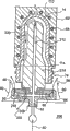
Figure 10 has represented an alternative embodiment of the invention, and it has made up cooling fluid is directly guided into end and the cooling effect of guiding preform neck finishing district outer surface in the prefabricated component.For easy understanding, represent with identical numbering similar in appearance to part shown in Figure 5.
In this embodiment, prefabricated component 14 keeps in present 62, and flange 114 is positioned on the end face of seat 62.Seat 62 can comprise cooling tube 64.Should be understood that, can select the mode of any or all cooling prefabricated component, thereby effectively cool off prefabricated component and not damaged best.
As adopt embodiment illustrated in fig. 5ly, and provide compressed air 80 to air duct 82, allow air inflow space 90 and by the gap 96 between insert 86 and the base plate 84.Base plate 84 is connected on the coldplate 206 by threaded fixture 208.Compressed air 80 flows along arrow 98 directions, and with the same way as of description embodiment illustrated in fig. 5, the neck finishing of cooling prefabricated component 14 distinguishes 74 thus.Difference in this embodiment is: compressed air 80 is also by the passage 212 in the cooling tube 214, dome 110 inner surfaces facing to prefabricated component 14 are discharged, and the inner surface of the prefabricated component 14 of flowing through is discharged the path shown in arrow 220 by the perforate in insert 86 and the base plate 84 218.
Adopt setting shown in Figure 10, the inner surface of prefabricated component 14 cools off the outer surface in neck finishing district 74 simultaneously by the air stream cooling by pipe 212.
Those skilled in the art are appreciated that, the invention is not restricted to example described herein, and they are envisioned for explanation and realize optimal mode of the present invention, and allow the setting and the details of operation of modification, size, part.The invention is intended to be included in all such modifications within the spirit and scope of claim regulation.
Claims (20)
1. one kind is used at the molded back cooling device that cools off prefabricated component (48), and described prefabricated component has an opening and an outer exposed surface area and an inside, and cooling device comprises:
A guiding piece that is positioned on the coldplate (206), guiding piece can be located in use and be abutted the opening that will cool off prefabricated component (48), but outside at opening, guiding piece comprises the wall of a guide channel, cooling agent is set in use to flow by described guide channel, guiding piece and guide channel transmit cooling agent and be directed to the above-mentioned outer exposed surface area of prefabricated component (48), and leave from prefabricated component inside, have cooled off the above-mentioned outer exposed surface area of prefabricated component thus emphatically.
2. according to the cooling device of claim 1, wherein said guiding piece also comprises:
An inlet is used to accept coolant source; And
A cavity is used in use the conduct coolant fluid from the above-mentioned outlet that enters the mouth, to discharge above-mentioned coolant fluid.
3. according to the cooling device of claim 2, wherein said guiding piece also comprises a base plate (84), be configured and be contained on the insert (86), wherein above-mentioned inlet is arranged in above-mentioned base plate (84), above-mentioned cavity is determined to be the space (90) between above-mentioned base plate (84) and above-mentioned insert (86), and above-mentioned outlet is arranged in i) above-mentioned base plate or ii) at least one of above-mentioned insert.
4. according to the cooling device of claim 3, also comprise a cooling tube (214) that is contained on the above-mentioned insert (86), when exposed surface area is exposed to above-mentioned cooling agent outside above-mentioned, above-mentioned cooling tube (214) stretches into above-mentioned prefabricated component (48) inside in use, above-mentioned cooling tube (214) comprise one be communicated with above-mentioned cavity open passage, to provide above-mentioned cooling agent to an inner surface.
5. according to the cooling device of claim 2 or 3, it further is configured the above-mentioned outer exposed surface area of restriction.
6. according to the cooling device of claim 5, many above-mentioned outlets are arranged wherein, be arranged to be used to discharge above-mentioned coolant fluid to above-mentioned outer exposed surface area in the face of described device inside.
7. according to the cooling device of claim 6, wherein above-mentioned outlet is arranged in many posts, the periphery of described a plurality of band of columns exposed surface area outside above-mentioned.
8. according to the cooling device of claim 6, wherein above-mentioned outlet is arranged to become an acute angle mode to discharge above-mentioned cooling agent to above-mentioned outer exposed surface area with respect to above-mentioned outer exposed surface area.
9. according to the cooling device of claim 6, also be included in the discharge-channel of base plate.
10. according to the cooling device of claim 9, wherein above-mentioned bottom parts (84) has a cup-shaped structure, above-mentioned insert (86) is contained in the above-mentioned base plate, one of them circumferential jet pipe gap is between above-mentioned insert and above-mentioned base plate, above-mentioned gap is determined by the inclined-plane on above-mentioned insert and above-mentioned base plate, thereby make above-mentioned cooling agent by the discharging of above-mentioned gap, cooling agent suction was on every side crossed in the cooling path of the above-mentioned outer exposed surface area that remains on the prefabricated component (48) in the above-mentioned seat (62).
11. according to the cooling device of claim 10, wherein above-mentioned jet pipe gap is Wen's jet pipe gap.
12. according to the cooling device of above arbitrary claim, the neck finishing district (74) that wherein above-mentioned outer exposed surface area is a prefabricated component.
13. according to the cooling device of claim 3, it is one of following that this base plate that wherein above-mentioned guiding piece comprises has:
A marginal zone, insert (86) is assemblied in the above-mentioned marginal zone, thereby forms a circular nozzle, to discharge above-mentioned compresses refrigerant outside above-mentioned on the exposed surface area; And
A marginal zone, insert (86) is limited in the above-mentioned marginal zone, and above-mentioned insert comprises several perforates (124,150), to discharge above-mentioned compresses refrigerant to above-mentioned outer exposed surface area (74) with predetermined direction in use.
14. according to the cooling device of claim 13, wherein above-mentioned predetermined direction be with above-mentioned outer exposed surface area at an angle, thereby make above-mentioned cooling agent to flow around the vortex form of above-mentioned outer exposed surface area.
15. according to the cooling device of claim 3, wherein the perforate (150) in an insert along be basically perpendicular to above-mentioned outside the direction guiding compresses refrigerant of exposed surface area.
16. cooling device according to claim 1, wherein above-mentioned prefabricated component remains in the seat (62) in use, described seat has a flange (114), is used to support above-mentioned prefabricated component (48), and flange (114) allows that above-mentioned outer exposed surface area is exposed in the above-mentioned compressed coolant stream.
17. a take-off plate (180) is used for the moulding press of prefabricated component, above-mentioned take-off plate comprises:
A plurality of seats (62) that are contained on the plate (180), each seat (62) keeps a prefabricated component (48) in use, and prefabricated component (48) has an outer exposed surface area; And
A cooling device that is used at molded back cooling prefabricated component (48), cooling device comprises: a guiding piece that is positioned on the coldplate (206), guiding piece can be located in use, abut the opening that will cool off prefabricated component (48), but outside at opening, guiding piece comprises the wall of a guide channel, cooling agent is set in use passes through channel flow, guiding piece and guide channel transmit cooling agent and be directed to the above-mentioned outer exposed surface area of prefabricated component (48), and leave from prefabricated component inside, cooled off the above-mentioned outer exposed surface area of prefabricated component thus emphatically.
18. according to the take-off plate of claim 17, wherein, described guiding piece also comprises:
A cooling agent disperser (182) is mounted close to the seat (62) of above-mentioned each prefabricated component;
Passage (186) in above-mentioned plate (180), above-mentioned passage (186) comprise a passage that feeds above-mentioned each disperser (182), and above-mentioned passage provides cooling agent to arrive above-mentioned each disperser (182) in use; And
Outlet (184) on each disperser (182), described each disperser is positioned at the lower part next door of prefabricated component in use, in use, above-mentioned outlet (184) is positioned on the above-mentioned seat (62) also close with it, thereby provides cooling agent to the above-mentioned exposed portions serve that remains on the above-mentioned prefabricated component (48) in the above-mentioned seat (62) in use.
19. according to the take-off plate of claim 17, wherein the cooling agent of above-mentioned supply is a compresses refrigerant.
20. according to the take-off plate of claim 18, wherein above-mentioned disperser (182) is connected to above-mentioned plate with keeper (188).
Applications Claiming Priority (3)
| Application Number | Priority Date | Filing Date | Title |
|---|---|---|---|
| US09/948,917 US6802705B2 (en) | 2001-09-10 | 2001-09-10 | Post mold cooling assembly for molded article neck finishes |
| US09/948,917 | 2001-09-10 | ||
| PCT/CA2002/000921 WO2003022548A1 (en) | 2001-09-10 | 2002-06-19 | Post mold cooling method and assembly for molded article neck finishes |
Publications (2)
| Publication Number | Publication Date |
|---|---|
| CN1553850A CN1553850A (en) | 2004-12-08 |
| CN1553850B true CN1553850B (en) | 2010-10-06 |
Family
ID=25488383
Family Applications (1)
| Application Number | Title | Priority Date | Filing Date |
|---|---|---|---|
| CN02817708.8A Expired - Fee Related CN1553850B (en) | 2001-09-10 | 2002-06-19 | Post mold cooling method and device for molded article neck finishes |
Country Status (9)
| Country | Link |
|---|---|
| US (1) | US6802705B2 (en) |
| EP (1) | EP1436134B1 (en) |
| JP (1) | JP4317449B2 (en) |
| CN (1) | CN1553850B (en) |
| AT (1) | ATE314187T1 (en) |
| CA (1) | CA2457084C (en) |
| DE (1) | DE60208410T2 (en) |
| MX (1) | MXPA04001998A (en) |
| WO (1) | WO2003022548A1 (en) |
Families Citing this family (26)
| Publication number | Priority date | Publication date | Assignee | Title |
|---|---|---|---|---|
| US6171541B1 (en) * | 1998-03-31 | 2001-01-09 | Husky Injection Molding Systems Ltd. | Preform post-mold cooling method and apparatus |
| ITRM20010138A1 (en) * | 2001-03-16 | 2002-09-16 | Sipa Spa | DEVICE AND METHOD FOR COOLING AND THERMAL CONDITIONING OF A TUBULAR OBJECT. |
| US7264464B2 (en) * | 2003-06-09 | 2007-09-04 | Husky Injection Molding Systems Ltd. | Cooling tube with a low friction coating |
| US7232306B2 (en) * | 2003-08-22 | 2007-06-19 | Graham Packaging Company, Lp | Modified injection takeout tube |
| JP4646526B2 (en) * | 2004-02-18 | 2011-03-09 | 株式会社日立製作所 | Storage control system and control method thereof |
| NL1026732C2 (en) * | 2004-07-27 | 2006-01-30 | Tool Tech Holding B V | Cooling device for preforms of plastic containers, as well as robot device provided with such a cooling device and production device for preforms provided with such a robot device. |
| US7550105B2 (en) * | 2005-02-23 | 2009-06-23 | Access Business Group International Llc | Apparatus and method for strengthening blow molded articles |
| JP2007144631A (en) * | 2005-11-24 | 2007-06-14 | Dainippon Printing Co Ltd | Takeoff jig of preform |
| DE102006028725A1 (en) * | 2005-11-30 | 2007-10-18 | Mht Mold & Hotrunner Technology Ag | Process and system for post-treatment of preforms |
| US20070264383A1 (en) * | 2006-05-12 | 2007-11-15 | Husky Injection Molding Systems Ltd. | Mold-cooling device having vortex-inducing cooling-fluid chamber |
| US7421310B2 (en) * | 2006-06-12 | 2008-09-02 | Husky Injection Molding Systems Ltd. | Method and apparatus for controlling cooling rates during post-mold cooling of a molded article |
| US20090200698A1 (en) * | 2006-06-12 | 2009-08-13 | Husky Injection Molding Systems Ltd. | Method and apparatus for post-mold cooling a molded article |
| US7485252B2 (en) | 2006-09-06 | 2009-02-03 | Graham Packaging Company, Lp | Method and apparatus for crystallizing the neck finish of a molded plastic article |
| US7595018B2 (en) * | 2006-10-16 | 2009-09-29 | Husky Injection Molding Systems Ltd. | Molded article picker |
| US7905721B2 (en) * | 2007-06-05 | 2011-03-15 | Husky Injection Molding Systems Ltd. | Air source device and a method for use in a molding system |
| US7780884B2 (en) * | 2007-08-20 | 2010-08-24 | Husky Injection Molding Systems Ltd. | Method for post-mold treatment of a molded article and an apparatus for implementing the method |
| ES2677870T3 (en) * | 2007-11-27 | 2018-08-07 | Plastipak Bawt S.À.R.L. | Cooling pin to cool a hollow molded plastic part through a flow of accelerated cooling fluid by venturi effect |
| CA2713824C (en) * | 2009-10-14 | 2016-01-26 | Pascal Zaffino | Mould with conformal cooling |
| US20190118442A9 (en) * | 2010-04-20 | 2019-04-25 | Honda Motor Co., Ltd. | Conforming cooling method and mold |
| JP5888731B2 (en) * | 2012-01-31 | 2016-03-22 | 日精エー・エス・ビー機械株式会社 | Mold apparatus, injection molding apparatus and injection molding method |
| DE102014205442A1 (en) | 2013-03-22 | 2014-09-25 | Otto Männer Innovation GmbH | Method and apparatus for tempering the neck finish area of molded preforms |
| CN103551508A (en) * | 2013-11-14 | 2014-02-05 | 邵宏 | Energy-saving lower metal die with heat radiating function |
| WO2015183279A1 (en) * | 2014-05-29 | 2015-12-03 | Discma Ag | Injection nozzle with finish cooling and counter pressure |
| US10369738B2 (en) | 2014-05-29 | 2019-08-06 | Discma Ag | Method of cooling a finish and providing counter pressure during forming of a container |
| CA3210826A1 (en) | 2015-01-13 | 2016-07-13 | Stackteck Systems Limited | Post-mold cooling method and apparatus with cyclone cooling effect |
| CN110181779A (en) * | 2019-06-28 | 2019-08-30 | 广东星联精密机械有限公司 | A kind of bottle base mould external cooling device |
Citations (4)
| Publication number | Priority date | Publication date | Assignee | Title |
|---|---|---|---|---|
| US5176871A (en) * | 1990-10-15 | 1993-01-05 | Nissei Asb Machine Co., Ltd. | Method of cooling a preform in a cooling tube |
| DE29810567U1 (en) * | 1998-06-12 | 1998-09-17 | Kronseder Maschf Krones | Device for conditioning preforms made of thermoplastic material |
| JP2000108170A (en) * | 1998-10-08 | 2000-04-18 | Mitsubishi Heavy Ind Ltd | Equipment for taking-out molded article |
| JP2001038779A (en) * | 1999-06-30 | 2001-02-13 | Hekuma Herbst Maschinenbau Gmbh | Method for controlling temperature and plastic material injection molding machine having handling device |
Family Cites Families (23)
| Publication number | Priority date | Publication date | Assignee | Title |
|---|---|---|---|---|
| US4285657A (en) | 1979-12-03 | 1981-08-25 | Ryder Leonard B | Injection blow molding apparatus |
| US4449913A (en) | 1981-02-23 | 1984-05-22 | The Continental Group, Inc. | Rotary injection turret for the making of preforms |
| US4729732A (en) | 1985-05-14 | 1988-03-08 | Husky Injection Molding Systems Ltd. | Carrying means for holding and cooling a parison |
| USRE33237E (en) | 1987-03-23 | 1990-06-19 | Husky Injection Molding Systems Ltd. | Apparatus for producing hollow plastic articles |
| US4950152A (en) | 1988-12-05 | 1990-08-21 | Electra Form, Inc. | Apparatus for producing preforms and blow molded articles |
| US5232715A (en) | 1990-10-15 | 1993-08-03 | Nissei Asb Machine Co., Ltd. | Apparatus for cooling a preform in a cooling tube |
| US5114327A (en) | 1991-01-25 | 1992-05-19 | Williamson James T | Rapid cooling apparatus for an injection molding machine |
| US5447426A (en) | 1993-07-06 | 1995-09-05 | Husky Injection Molding Systems Ltd. | Take-off plate device |
| JPH07171888A (en) | 1993-12-21 | 1995-07-11 | Koyo Jidoki Kk | Preform forced-cooling device |
| US5702734A (en) | 1994-12-19 | 1997-12-30 | Electra Form, Inc. | Take-out and cooling apparatus |
| CA2160644C (en) | 1995-10-16 | 2005-05-24 | Jobst Ulrich Gellert | Cooled thread split inserts for injection molding preforms |
| US5707662A (en) | 1995-11-01 | 1998-01-13 | Electra Form, Inc. | Parison molding and cooling apparatus |
| US5728409A (en) | 1996-03-06 | 1998-03-17 | Husky Injection Molding Systems Ltd. | Turret article molding machine |
| NL1005872C2 (en) | 1997-04-22 | 1998-10-29 | Inter Tooling Services Bv | Injection molding machine for injection molding preforms for plastic bottles and similar containers. |
| US6171541B1 (en) * | 1998-03-31 | 2001-01-09 | Husky Injection Molding Systems Ltd. | Preform post-mold cooling method and apparatus |
| US6461556B2 (en) * | 1998-03-31 | 2002-10-08 | Husky Injection Molding Systems, Ltd. | Post-mold cooling method and apparatus |
| JP3076033B1 (en) * | 1998-09-14 | 2000-08-14 | 松下電器産業株式会社 | Optical information recording / reproducing apparatus and information recording medium |
| US6059557A (en) | 1998-10-07 | 2000-05-09 | Husky Injection Molding Systems Ltd. | Cooling device attached to index machine |
| CA2255798C (en) | 1998-12-07 | 2008-06-17 | Jobst Ulrich Gellert | Injection molding cooling core having spiral grooves |
| JP2001018265A (en) | 1999-06-30 | 2001-01-23 | Hekuma Herbst Maschinenbau Gmbh | Apparatus and method for handling resin product |
| US6223541B1 (en) * | 1999-08-17 | 2001-05-01 | Fasti, Farrag & Stipsits Gesmbh | Method and device for the after-cooling of a preform in the injection molding process |
| US6299804B1 (en) | 1999-09-16 | 2001-10-09 | Husky Injection Molding Systems Ltd. | Air cooling system for preform molding |
| CH695332A5 (en) | 2000-12-22 | 2006-04-13 | Netstal Ag Maschf Giesserei | Cooler for sleeve-shaped injection molded parts, as well as the use of the after-cooler. |
-
2001
- 2001-09-10 US US09/948,917 patent/US6802705B2/en not_active Expired - Fee Related
-
2002
- 2002-06-19 JP JP2003526655A patent/JP4317449B2/en not_active Expired - Fee Related
- 2002-06-19 CA CA002457084A patent/CA2457084C/en not_active Expired - Fee Related
- 2002-06-19 MX MXPA04001998A patent/MXPA04001998A/en active IP Right Grant
- 2002-06-19 CN CN02817708.8A patent/CN1553850B/en not_active Expired - Fee Related
- 2002-06-19 AT AT02742586T patent/ATE314187T1/en active
- 2002-06-19 DE DE60208410T patent/DE60208410T2/en not_active Expired - Lifetime
- 2002-06-19 WO PCT/CA2002/000921 patent/WO2003022548A1/en active IP Right Grant
- 2002-06-19 EP EP02742586A patent/EP1436134B1/en not_active Expired - Lifetime
Patent Citations (4)
| Publication number | Priority date | Publication date | Assignee | Title |
|---|---|---|---|---|
| US5176871A (en) * | 1990-10-15 | 1993-01-05 | Nissei Asb Machine Co., Ltd. | Method of cooling a preform in a cooling tube |
| DE29810567U1 (en) * | 1998-06-12 | 1998-09-17 | Kronseder Maschf Krones | Device for conditioning preforms made of thermoplastic material |
| JP2000108170A (en) * | 1998-10-08 | 2000-04-18 | Mitsubishi Heavy Ind Ltd | Equipment for taking-out molded article |
| JP2001038779A (en) * | 1999-06-30 | 2001-02-13 | Hekuma Herbst Maschinenbau Gmbh | Method for controlling temperature and plastic material injection molding machine having handling device |
Non-Patent Citations (1)
| Title |
|---|
| US 5176871 A, |
Also Published As
| Publication number | Publication date |
|---|---|
| US6802705B2 (en) | 2004-10-12 |
| CN1553850A (en) | 2004-12-08 |
| DE60208410D1 (en) | 2006-02-02 |
| MXPA04001998A (en) | 2004-07-08 |
| WO2003022548A1 (en) | 2003-03-20 |
| CA2457084A1 (en) | 2003-03-20 |
| US20030057598A1 (en) | 2003-03-27 |
| ATE314187T1 (en) | 2006-01-15 |
| JP4317449B2 (en) | 2009-08-19 |
| DE60208410T2 (en) | 2006-09-07 |
| EP1436134B1 (en) | 2005-12-28 |
| EP1436134A1 (en) | 2004-07-14 |
| JP2005501765A (en) | 2005-01-20 |
| CA2457084C (en) | 2007-10-30 |
Similar Documents
| Publication | Publication Date | Title |
|---|---|---|
| CN1553850B (en) | Post mold cooling method and device for molded article neck finishes | |
| US6957954B2 (en) | Post-mold cooling apparatus | |
| JP4358715B2 (en) | Molded product cooling system and cooling method, cooling pin | |
| US6461556B2 (en) | Post-mold cooling method and apparatus | |
| US4473515A (en) | Injection blow molding method | |
| US4285657A (en) | Injection blow molding apparatus | |
| CA1197960A (en) | Injection blow molding | |
| US6770239B2 (en) | Method for localized preform cooling outside the mold | |
| US5176871A (en) | Method of cooling a preform in a cooling tube | |
| US5232715A (en) | Apparatus for cooling a preform in a cooling tube | |
| US4344749A (en) | Injection stretch-blow molding apparatus for the manufacture of biaxially oriented hollow bodies from thermoplastic material | |
| JPH06278196A (en) | Blow molding machine | |
| US6682690B2 (en) | Core rod positioning method | |
| JP7279025B2 (en) | Injection mold, lip mold included therein, and injection molding method | |
| EP1260339B1 (en) | Preform post-mold cooling method and apparatus, and cooling pin |
Legal Events
| Date | Code | Title | Description |
|---|---|---|---|
| C06 | Publication | ||
| PB01 | Publication | ||
| C10 | Entry into substantive examination | ||
| SE01 | Entry into force of request for substantive examination | ||
| C14 | Grant of patent or utility model | ||
| GR01 | Patent grant | ||
| CF01 | Termination of patent right due to non-payment of annual fee |
Granted publication date: 20101006 Termination date: 20140619 |
|
| EXPY | Termination of patent right or utility model |