CN1550012A - Two-sided replication of data storage media - Google Patents
Two-sided replication of data storage media Download PDFInfo
- Publication number
- CN1550012A CN1550012A CNA028143329A CN02814332A CN1550012A CN 1550012 A CN1550012 A CN 1550012A CN A028143329 A CNA028143329 A CN A028143329A CN 02814332 A CN02814332 A CN 02814332A CN 1550012 A CN1550012 A CN 1550012A
- Authority
- CN
- China
- Prior art keywords
- photopolymer
- edge body
- substrate
- sided
- pressing mold
- Prior art date
- Legal status (The legal status is an assumption and is not a legal conclusion. Google has not performed a legal analysis and makes no representation as to the accuracy of the status listed.)
- Granted
Links
Images


Classifications
-
- B—PERFORMING OPERATIONS; TRANSPORTING
- B29—WORKING OF PLASTICS; WORKING OF SUBSTANCES IN A PLASTIC STATE IN GENERAL
- B29D—PRODUCING PARTICULAR ARTICLES FROM PLASTICS OR FROM SUBSTANCES IN A PLASTIC STATE
- B29D17/00—Producing carriers of records containing fine grooves or impressions, e.g. disc records for needle playback, cylinder records; Producing record discs from master stencils
- B29D17/005—Producing optically read record carriers, e.g. optical discs
-
- G—PHYSICS
- G11—INFORMATION STORAGE
- G11B—INFORMATION STORAGE BASED ON RELATIVE MOVEMENT BETWEEN RECORD CARRIER AND TRANSDUCER
- G11B7/00—Recording or reproducing by optical means, e.g. recording using a thermal beam of optical radiation by modifying optical properties or the physical structure, reproducing using an optical beam at lower power by sensing optical properties; Record carriers therefor
- G11B7/24—Record carriers characterised by shape, structure or physical properties, or by the selection of the material
- G11B7/26—Apparatus or processes specially adapted for the manufacture of record carriers
- G11B7/263—Preparing and using a stamper, e.g. pressing or injection molding substrates
-
- G—PHYSICS
- G11—INFORMATION STORAGE
- G11B—INFORMATION STORAGE BASED ON RELATIVE MOVEMENT BETWEEN RECORD CARRIER AND TRANSDUCER
- G11B11/00—Recording on or reproducing from the same record carrier wherein for these two operations the methods are covered by different main groups of groups G11B3/00 - G11B7/00 or by different subgroups of group G11B9/00; Record carriers therefor
- G11B11/10—Recording on or reproducing from the same record carrier wherein for these two operations the methods are covered by different main groups of groups G11B3/00 - G11B7/00 or by different subgroups of group G11B9/00; Record carriers therefor using recording by magnetic means or other means for magnetisation or demagnetisation of a record carrier, e.g. light induced spin magnetisation; Demagnetisation by thermal or stress means in the presence or not of an orienting magnetic field
- G11B11/105—Recording on or reproducing from the same record carrier wherein for these two operations the methods are covered by different main groups of groups G11B3/00 - G11B7/00 or by different subgroups of group G11B9/00; Record carriers therefor using recording by magnetic means or other means for magnetisation or demagnetisation of a record carrier, e.g. light induced spin magnetisation; Demagnetisation by thermal or stress means in the presence or not of an orienting magnetic field using a beam of light or a magnetic field for recording by change of magnetisation and a beam of light for reproducing, i.e. magneto-optical, e.g. light-induced thermomagnetic recording, spin magnetisation recording, Kerr or Faraday effect reproducing
- G11B11/10582—Record carriers characterised by the selection of the material or by the structure or form
Landscapes
- Engineering & Computer Science (AREA)
- Manufacturing & Machinery (AREA)
- Mechanical Engineering (AREA)
- Manufacturing Optical Record Carriers (AREA)
- Optical Record Carriers And Manufacture Thereof (AREA)
Abstract
The invention is directed towards techniques for creating optical data storage disks. In one embodiment, the invention provides a simultaneous two-sided rolling bead process. For example, a method may include positioning a first bead of photopolymer for distribution between a bottom stamper and a substrate, and positioning a second bead of photopolymer for distribution between a top stamper and the substrate. The method may also include passing a roller over the top stamper to distribute the beads of photopolymer, curing the photopolymer, and removing the substrate from the stampers. The simultaneous two-sided rolling bead process can be repeated on the same medium to create a two-sided dual-layer data storage medium or a two-sided multi-layer data storage medium.
Description
Technical field
The present invention relates to the manufacturing of the data storage medium such as optical data storage disc.
Background technology
For storing, distribute and retrieve a large amount of information, use and accepted extensively by people such as the optical medium of optical data storage disc.Optical data storage disc for example comprises: audio frequency CD (laser disc), CD-R (compact disc recordable), CD-ROM (CD-ROM (read-only memory)), DVD (digital universal disc or Digital video disc) medium, DVD-RAM (DVD-random access memory) and various types of rewritable media, and such as magneto-optic (MO) dish and phase change disc.For optical data storage disc, more all has storage capacity on two faces of the dish of format at some.In addition, some more the optical storage disc of format just towards the direction effort of littler dish size.
Optical data storage disc can produce by at first manufacturing a master, and described master has picture on surface, and this picture on surface is represented the lip-deep coded data of described master.Described picture on surface for example can be many grooves, and described groove limits the concave point of master and the piston ring land of master.Described master is created by relatively costly master manufacturing process usually.After creating suitable master, therefore this master can be used for making pressing mold.Described pressing mold has picture on surface, the reverse pattern of the picture on surface that described picture on surface is just encoded on master.Then, in producing punching course in batches, can use described pressing mold to suppress a large amount of replicating disks, the all rolling in this way edge bodies of described batch process punching course (rolling bead) process, as by the 4th, 374, No. 077 United States Patent (USP) the present inventor instructed like that.
In rolling edge body process, photopolymer edge body is arranged on the position between substrate and the described pressing mold.A roll printed above substrate and pressing mold, photopolymer edge body is scatter, and forced air entered the forward position of edge body.When described roller after printing on this substrate and the pressing mold and photopolymer scatter, can utilize ultraviolet ray (UV) light to solidify described photopolymer.Peel off pressing mold then, solidifying an inversion pattern that in the photopolymer of described substrate, stays this pressing mold.Then, can be on described photopolymer deposit reflecting material, phase-change material, magneto-optic memory technique or the like.Can also add the additional protection layer.
Summary of the invention
Put it briefly, the object of the present invention is to provide a kind of technology that is used to create optical data storage disc.Specifically, the object of the present invention is to provide a kind of technology that is used to create two-sided optical data storage disc, perhaps in other words, relate to a kind of can be on two-sided the dish of canned data.In certain embodiments, this technology can be used for creating two-sided double-deck optical data storage disc.In these cases, can be on two faces of this dish with two-layer information stores.
In one embodiment, the invention provides two-sided rolling edge body process of a kind of while.For example, a kind of method can comprise: place the first photopolymer edge body, so that between bottom pressing mold and substrate, distribute this first photopolymer edge body, and place the second photopolymer edge body, so that between top pressing mold and substrate, distribute this second photopolymer edge body.Described method also can comprise printed roller on the pressing mold of described top, so that distribute described photopolymer edge body, solidify described photopolymer, and eliminated described substrate from described pressing mold.
Curing photopolymer layer on described substrate is two-sided limits the Information Level on this medium.Can be according to the medium format deposition materials on described Information Level.For example, according to the media type that is created, can the deposit phase-change material, magneto-optic memory technique or reflecting material.Reflecting material can be used for limiting read-only form, and perhaps as an alternative, phase-change material or magneto-optic memory technique can be used for limiting write-once (write-once) but or rewritable format.
Two-sided rolling edge body process of described while can be repeated so that create additional information layer on described medium two-sided.For example, in one embodiment, first while, two-sided rolling edge body process can be followed the deposit of phase-change material.Then, can be to same two-sided rolling edge body process of second while of media applications, described two-sided rolling edge body process of second while is followed the deposit of reflecting material.The outermost cage that is limited by reflecting material can be translucent, so that some light can penetrate described reflection horizon.This described phase-change material that can guarantee to be deposited on the internal information layer can be changed and/or detection optically optically by disc driver.
In two-sided two-layered medium, described external information layer needs enough thickness, with avoid medium with on the one side, be stored in the information on the described exterior layer and the light wave interference that is stored between the information on the interior layer.In other words, being deposited on the material on the described external information layer and being deposited between the material on the internal information layer needs enough distances, can focus light rays at the surface of internal information layer so that guarantee CD-ROM drive, and not be subjected to the interference of external information layer.The viscosity that is used to create the photopolymer of described Information Level can be predetermined, so that control the thickness of described Information Level.For example, the photopolymer that uses in the two-sided at the same time rolling edge body process can have sufficiently high viscosity, so that Information Level has suitable thickness.Specifically, the external information layer needs about 50 μ m or bigger thickness.
The invention provides many advantages.For example, the present invention can be used for realizing having the optical data storage disc that has improved data storage capacities.In addition, the present invention can be used for realizing the blended data memory disc, but has both read-only form and write-once or rewritable format on this dish two-sided.But the dish that has both read-only form and rewritable format is especially favourable to following application, in this described application, when storage needs some information of permanent storage, also can store other information, abandons then or replaces.
Also provide advantage aspect the information layer thicknesses optimization according to technology of the present invention making.Specifically, for two-sided dual layer discs, the thickness of external information layer needs enough thick, so that avoid being deposited on this dish with the interference between the material on the corresponding information layer on the one side.By pre-determining the viscosity of employed photopolymer, the invention provides a kind of easy relatively mode and come the control information layer thickness.The pressure and the mill speed that are used for the roller of two-sided rolling edge body process of described while can also be controlled to the prescribed information layer thickness.For the external information layer, the thickness that has about 50 μ m just is enough to avoid interference.
Another advantage can realize in the following manner that described mode is: use the dish of oversize during two-sided rolling edge body process, and then the dish of this oversize is stamped into due size.Can avoid the relevant problem of outer boundary place variation in thickness with the dish of oversize like this, wherein when described substrate be one when injecting the mold pressing substrate, the dish of described oversize may appear.The present invention also provides and has been better than the advantage that other are used to create the method for two-sided double-deck optical data storage disc.Specifically, for the exterior layer of dual layer discs, conventional spin coating technique is being unaccommodated aspect the even information layer thicknesses of establishment.In addition, because spin coating technique utilizes the effect of gravity in coating procedure, so spin coating technique usually need be to each face spin coated independently of dish.Can cause the flaw that coils and the variation in thickness of described spin coated photopolymer like this.Yet, according to two-sided rolling edge body process of the present invention unrestricted aspect this.
In described the accompanying drawings and the description below, set forth the subsidiary details of these and other embodiment.Other feature, purpose and advantage will be by explanation and accompanying drawings, and become apparent by claims.
Description of drawings
Fig. 1 is the process flow diagram according to one embodiment of the present of invention.
Fig. 2 A-2C is the side cross-sectional view of two-sided rolling edge system.
Fig. 3 is the another process flow diagram according to one embodiment of the invention.
Fig. 4 be according to of the present invention, illustrate the process flow diagram that relates to addressing information layer thicknesses process.
Fig. 5 is the process flow diagram that illustrates the process that is used to create two-sided double-deck optical data carrier in more detail.
Fig. 6 is the process flow diagram that illustrates the process of the two-sided double-deck optical data carrier that is used to create specific format.
Fig. 7-the 11st, the side cross-sectional view of exemplary data storage medium, described data storage medium can use according to one or more technology of the present invention and create.
Embodiment
The invention provides the technology that is used to create optical data storage disc.For example, the invention provides a kind of two-sided rolling edge body process, be used to create two-sided data storage medium.Described two-sided rolling edge body process can repeat more than once identical data storage medium, so that create two-sided double-deck optical data carrier or double-sided multi-layer optical data carrier.After each two-sided rolling edge body process of execution, deposition materials on the one or both sides of described data storage medium.By this way, each of two-sided data storage medium layer can both limit according to desired data memory format, and described data memory format for example is prerecorded, phase transformation or magneto-optic.
Fig. 1 is the process flow diagram according to the embodiment of the invention.As shown in the figure, place the first photopolymer edge body, so that between bottom pressing mold and substrate, distribute this first photopolymer edge body (12).In addition, place the second photopolymer edge body, so that between top pressing mold and substrate, distribute this second photopolymer edge body (14).Then, roller printed on the pressing mold of top, so as on each face of substrate even distribution photopolymer edge body (16).The bottom pressing mold can be supported by general fixing area supported.Each pressing mold can comprise groove, is used to limit a kind of pattern of expression coded message.Described photopolymer is filled in the groove of pressing mold, forms a picture on surface, and the pattern that described picture on surface and this pressing mold limit is reverse.By on the pressing mold of top, printed roller, with distribution photopolymer edge body, air is removed and is driven to the forward position of described edge body from the groove of pressing mold.
In case described roll marks is crossed the top pressing mold, photopolymer edge body just is dispersed in the top and the lower surface of substrate equably, other patterns of having filled groove thus or having limited on stamper surface.At this point, described photopolymer can be solidified (18) by UV, make photopolymer be adhered to described substrate thus, and keeps the reverse pattern of pressing mold in photopolymer.Therefore described substrate can be peeled off or remove (19) from pressing mold.In order to be easy to peel off, described pressing mold can be coated with suitable release agent or the like.
One of pressing mold or two can be made translucent so that can carry out photopolymer and solidify (18) by ultraviolet directly being penetrated translucent pressing mold.For example, the plastics pressing mold of polycarbonate pressing mold, polymethylmethacrylate (PMMA) pressing mold or polyester pressing mold and so on generally all is translucent for ultraviolet light.If substrate also is translucent to ultraviolet light, it need be translucent having only a pressing mold so.Under the sort of situation, other pressing molds can be lighttight, thus as much as possible the ultraviolet light of reflecting ﹠ transmitting substrate so that further solidify described photopolymer.In other cases, two pressing molds are all made translucent.In these situations, ultraviolet light can directly penetrate two pressing molds so that solidify described photopolymer.
For instance, can comprise according to suitable photopolymer used in the present invention: HDDA (4x6x) polyene key unsaturated monomer---hexanediol olefin(e) acid ester (hexanedioldiacrylate), chemlink 102 (3x) monoethylenically unsaturated monomer---DGDE acrylates (diethylene glycol monethyl ether acrylate), elvacite 2043 (lx3x) organic polymer---polyethyl methacrylate (polyethylmethacrylate), and irgacure 651 (.lx.2) the radical initiating agent of hiding---benzoin dimethylether (2,2-dimethyoxy-2-phenylacetophenone).Other photopolymer that is fit to comprises HHA (hydantoins six acrylates, hydantoinhexacryulate) 1x, HDDA (hexanediol olefin(e) acid ester) 1x and irgacure 651 (.lx.2) radical initiating agent---the benzoin dimethylether of hiding.These or other photopolymer can use according to the present invention.
More particularly, photopolymer can comprise 49% hydantoins six acrylic acid salt, 49% hexanediol olefin(e) acid ester, and 2% benzoin dimethylether.Perhaps as an alternative, comprise 40% hexanediol olefin(e) acid ester, 29% hexanediol monoethyl ether acrylates (glycol monethyl ether acrylate), 29% polyethyl methacrylate (polyethyl methacrylate) and 2% benzoin dimethylether.As following explanation in further detail, can change different number percent and form so that change the viscosity of employed photopolymer.Specifically, in two-sided rolling edge body process, when using the roller of specific uniform pressure and speed, tackifying to produce thicker Information Level.Yet the photopolymer composition of preferentially selecting for use comprises 2% benzoin dimethylether all the time.
Fig. 2 A-2C is the side cross-sectional view of two-sided rolling edge system.Described system can comprise top pressing mold 22, bottom pressing mold 24 and roller 26.Top and bottom pressing mold can be placed in die module 23 and 25, but the invention is not restricted to this.For example, pressing mold 22 and 24 can for good and all be fixed in die module 23 and 25, and perhaps as an alternative, pressing mold 22 and 24 can take off from die module 23 and 25.If described pressing mold is removable,, various pressing mold can be inserted in the die module 23 and 25 so according to groove pattern to be duplicated. Pressing mold 22 and 24 can relative to each other and correctly be located, so that guarantee to copy to the top of substrate 28 and the Information Level on the lower surface concentrically with respect to one another.
In order to create optical data carrier, substrate 28 is arranged between pressing mold 22 and 24.The first photopolymer edge body 30 is placed, so that at this first photopolymer edge body 30 that distributes between the bottom surface of bottom pressing mold 24 and substrate 28.Similarly, place the second photopolymer edge body 32, so that between the bottom surface of top pressing mold 22 and substrate 28, distribute this second photopolymer edge body 32.By spraying, can correctly determine the position of photopolymer edge body 30,32 via jet pipe, thrower, suction pipe or the like. Photopolymer edge body 30,32 should be placed on the position of the zone one section small distance before in the substrate 28 at least, and the pattern that the zone in the described substrate 28 will be utilized on the pressing mold 22,24 is encoded.
Then, roller 26 by top pressing mold 22 so that photopolymer edge body 30,32 is spread out, as shown in Fig. 2 B.Described photopolymer is filled the groove of pressing mold 22,24, forms the picture on surface that is limited by pressing mold.Air is removed from the groove of pressing mold, and forced it to arrive the forward position of edge body 30,32.
As shown in Fig. 2 A-2C, when roller 26 passes through top pressing mold 22, roller 26 spread out photopolymer edge body 30,32 in the following manner, that is: according on each respective face about equally thickness, be dispersed in the top and the lower surface of substrate 28 equably basically.Yet,, do not resemble and localize the pressure that is applied to top layer so that be applied to the pressure of bottom, so bottom can be thicker slightly than top layer because substrate 28 disperses the pressure of rollers 26.At this point, photopolymer can be solidified so that the Information Level on 28 two faces of qualification substrate.Described solidification process bonds to photopolymer on the substrate 28, and keeps the picture on surface that is limited by pressing mold 22 and 24.After solidifying, pressing mold 22 and 24 can be peeled off, and can remove substrate 28.Then can according to desired medium format, on described Information Level deposition materials.
Illustrate with form according to substrate 28 greater than pressing mold 22 and 24.This is optional, but can provide advantage aspect mass of medium.Last data storage medium can perhaps be removed from the substrate of oversize by punch press.Substrate 28 is carried out stamping to produce less dish, can avoid the relevant problem of variation in thickness with the outer boundary place of substrate 28.
Fig. 3 is the another process flow diagram according to the embodiment of the invention.As shown in the figure, provide substrate (34).Described substrate provides the mechanical stability of medium usually.For example, described substrate can be made up of PMMA, polycarbonate or aluminium.With regard to intensity and stability, aluminium provides advantage.In addition, aspect the bonding adhesion strength, aluminium provides advantage between substrate and photopolymer.But aluminium is lighttight.Thus, under the situation that must need translucent substrate, that is: when one of them pressing mold be lighttight and ultraviolet light directly sees through substrate so that when photopolymer being solidificated on the opposite side of substrate, PMMA and polycarbonate may be more desirable.
Then on substrate is two-sided, use simultaneously two-sided rolling edge body process to create Information Level (36).For example, can use the process that is similar to Fig. 1 illustrated.Then, according to desired medium format, with deposition of materials (38) to Information Level.For example, if Information Level is read-only Information Level, the reflection horizon can be deposited on the Information Level so.Nickel or aluminium can be used for realizing the reflection horizon that is fit to.How many reflection horizon desirable thickness can according to deciding that described layer needs are reflected.For example, if add a plurality of Information Levels to a kind of medium, outermost cage need be translucent so, so that some light can detect the internal information layer by the penetrate through reflective layer.Under the sort of situation, having the thick nickel dam of general 10nm or having the thick aluminium lamination of general 20nm to provide suitable translucent reflective layer.
Yet if add described reflection horizon a kind of inner most Information Level of medium to, so opaque reflection horizon may be more desirable.Under the sort of situation, can use to have the thick nickel dam of general 25nm or have the thick aluminium lamination of general 50nm.As the alternative of translucent reflective layer, can use comprise silicon, oxygen and nitrogen such as SiO
xN
yDielectric layer.
If but described Information Level is write-once or rewritable layer, so can be on Information Level deposit phase-change material or magneto-optic memory technique.For example, described phase-change material can comprise that phase transformation piles up.Two such examples comprise the GST that piles up as silver/tellurium/germanium, and comprise the AIST that piles up as silver/indium/antimony/tellurium.Can also use other phase-change materials.
According to medium format, deposition of materials (38) on described Information Level can be that same medium repeats the process of Fig. 3 afterwards.By this way, can create two-sided bilayer or double-sided multi-layer medium.Different layers can be limited by the material that is deposited on the specific information layer.Yet, when comprising more than one layer on the same one side of double side dielectric, an extra difficult problem has appearred.One of this difficult problem relates to the level of transparency in reflection horizon.As mentioned above, if add the reflection horizon to outmost Information Level, so described reflection horizon need be translucent, so that at least some light can be penetrated into interior layer.
Another difficult problem relates to the thickness of Information Level.Specifically, if comprise a plurality of Information Levels on the same one side of a double side dielectric, the external information layer needs enough thickly so, with box lunch light focusing on specific layer the time, is avoided the interference between these layers.
Fig. 4 is according to the present invention, illustrates the relevant process flow diagram that addresses the process of information layer thicknesses.As shown in the figure, provide substrate (42), and the photopolymer with the viscosity of pre-determining (44) is provided.Therefore Information Level with specific thicknesses can use two-sided rolling edge body process of while to create (46).Determine that suitable photopolymer viscosity is a kind of fairly simple mode that is used for the thickness of prescribed information layer.Photopolymer is sticking more, will produce thick more Information Level.The pressure of the roller that printed on described pressing mold and mill speed also can influence information layer thicknesses.For example, big more pressure and slow more mill speed produce thin more Information Level usually.
Yet, control easier process and set up the fixedly draught pressure of roller and fixing mill speed.For instance, photopolymer can comprise 49% hydantoins hexacrylate, 49% hexanediol olefin(e) acid ester, and 2% benzoin dimethylether.As an alternative, described photopolymer can comprise 40% hexanediol olefin(e) acid ester, 29% glycol ethyl ether acrylates, 29% polyethyl methacrylate and 2% benzoin dimethylether.Described 2% benzoin dimethylether is generally fixed.Yet other compositions can change, so that change the viscosity of described photopolymer.Importantly, viscosity is high more, will produce thick more Information Level, and viscosity is low more, will produce thin more Information Level.
In first tentative example, deposit viscosity is about the photopolymer of 500 centipoises on medium two-sided.On the mill speed of 6.35mm/s, apply the draught pressure that produces by cylinder with 620 kPas of adjustings.As a result of the medium of Chan Shenging has the thick top information layer of about 4 μ m, and has the thick bottom Information Level of about 7 μ m.
In second tentative example, deposit viscosity is about the photopolymer of 1000 centipoises on medium two-sided.On the mill speed of 12.7mm/s, apply the draught pressure that produces by cylinder with 620 kPas of adjustings.As a result of the medium of Chan Shenging has thick top information layer of about 13 μ m and the thick bottom Information Level of about 16 μ m.
In the 3rd tentative example, deposit viscosity is about the photopolymer of 5000 centipoises on medium two-sided.On the mill speed of 12.7mm/s, apply the draught pressure that produces by cylinder with 550 kPas of adjustings.As a result of the medium of Chan Shenging has thick top information layer thickness of about 48 μ m and the thick bottom Information Level of about 55 μ m.
If comprise a plurality of layers on the same one side of double side dielectric, so described innermost layer generally can have thickness arbitrarily.Yet described exterior layer needs general 50 μ m or bigger thickness to avoid the light wave between exterior layer and the interior layer to disturb.In an example, two-sided double-deck optical data storage disc comprises interior layer and exterior layer, and described interior layer has the thickness of general 5 μ m, and described exterior layer has the thickness of about 50 μ m.The first above-mentioned tentative example can be used for realizing having the thick interior layer of about 5 μ m, and the 3rd above-mentioned tentative example can be used for realizing having the thick exterior layer of about 50 μ m.
When being provided with in the two-sided rolling edge body process at the same time, on substrate is two-sided when having the photopolymer edge body of identical viscosity, the Information Level on the substrate bottom can be thicker slightly than the Information Level on the substrate top.Above-mentioned tentative example is supported this conclusion.The reason that changes relates to the pressure reduction that is applied to top and bottom layer.Described roller is applied to top layer with more local pressure.The substrate described pressure that so distributes that is: makes the pressure ratio that is applied to bottom be applied to the pressure of top layer by littler localization.
Variation in thickness between top and the bottom layer can be approximately 3 μ m, and trending towards along with the increase of information layer thicknesses increases.In most of the cases, the variation of about 3 μ m may not necessarily cause tangible problem to mass of medium.Yet, if at the top of substrate during with the accurate more similar thickness of each layer needs on the bottom, when perhaps if the information layer thicknesses of Zeng Jiaing makes variation between the thickness of top and bottom layer greater than desired value, the viscosity of the photopolymer edge body that distributes between bottom pressing mold and substrate is placed so so that can be made into less than being placed so that the viscosity of the photopolymer edge body that distributes between top pressing mold and substrate.By this way, the bottom information layer thicknesses can be formed within the scope of top information layer thickness of 3 μ m.In fact, described thickness even can all make equates basically.
Fig. 5 is the process flow diagram that illustrates the process that is used to create two-sided double-deck optical data carrier in more detail, as shown in the figure, provides substrate (52).Then, on substrate two-sided, use first simultaneously two-sided rolling edge body process create first information layer (54) with specific thicknesses.Then, according to medium format, with deposition of materials (56) on first information layer.Then, on substrate two-sided, use second simultaneously two-sided rolling edge body process create second Information Level (58) with specific thicknesses.Then, according to medium format, with deposition of materials (59) on second Information Level.Though in Fig. 5, do not illustrate,, can also use third and fourth simultaneously two-sided rolling edge body process for example create the extra play of the 3rd layer and the 4th layer.After creating each Information Level, according to medium format, on described Information Level deposition materials.
Fig. 6 is the process flow diagram that illustrates the process of a specific format that is used to create two-sided double-deck optical data carrier.As shown in the figure, provide substrate (62).Described substrate can be to have the thick polycarbonate substrate of about 500 μ rn.Then, on described substrate two-sided, use first simultaneously two-sided rolling edge body process create and have the thick first information layer (64) of about 5 μ rn.Then, phase-change material is deposited on (66) on the first information layer.Then, on described substrate two-sided, use second simultaneously two-sided rolling edge body process create and have thick second Information Level (68) of about 50 μ rn.Then, reflecting material is deposited on described second Information Level (69).Equally, described during fabrication medium may be an oversize, then punch press or cut out so that avoid the relevant problem of medium edge place variation in thickness with oversize.
Fig. 7-the 11st, the side cross-sectional view of exemplary data storage medium, described data storage medium can be to use one or more technology described herein to create.As shown in Figure 7, data storage medium 70 comprises substrate 71 and is positioned at Information Level 72 and 73 on the opposite sides of substrate 71.Illuvium 74 and 75 resides in the top of each Information Level 72 and 72.For example, illuvium 74 and 75 can comprise reflecting material, magneto-optic memory technique or phase-change material.
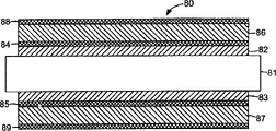
Fig. 8 for example understands two-sided double-deck optical data carrier 80.Medium 80 comprises substrate 81 and the first information layer 82 and 83 on the opposite sides of substrate 81. First reflection horizon 84 and 85 is deposited on each layer of first information layer 82 and 83. Second Information Level 86 and 87 is present on the top of first reflection horizon 84 and 85, and second reflection horizon 88 and 89 is deposited on described second Information Level 86 and 87.
Fig. 9 for example understands another kind of two-sided double-deck optical data carrier 90.Medium 90 comprises substrate 91 and the first information layer 92 and 93 on the opposite sides of substrate 91.Phase change layer 94 and 95 is deposited on each layer of first information layer 92 and 93.Second Information Level 96 and 97 is present on the top of phase change layer 94 and 95, and reflection horizon 98 and 99 is deposited on described second Information Level 96 and 97.
Figure 10 for example understands another two-sided double-deck optical data carrier 100.Medium 100 comprises substrate 101 and the first information layer 102 and 103 on the opposite sides of substrate 101.Phase change layer 104 is deposited on the first information layer 102, and first reflection horizon 105 is deposited on the first information layer 103. Second Information Level 106 and 107 is present on the top in the phase change layer 104 and first reflection horizon 105. Second reflection horizon 108 and 109 is deposited on described second Information Level 106 and 107.
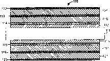
Figure 11 for example understands two-sided three layers of optical data carrier 110.Medium 110 comprises substrate 111 and the first information layer 112 and 113 on the opposite sides of substrate 111. Phase change layer 114 and 115 is deposited on each layer of first information layer 112 and 113. Second Information Level 116 and 117 is present on the top of phase change layer 114 and 115, and first reflection horizon 118 and 119 is deposited on described second Information Level 116 and 117.The 3rd Information Level 120 and 121 is present on the top of described second Information Level 116 and 117, and second reflection horizon 122 and 123 is deposited on described the 3rd Information Level 120 and 121.
The medium that also has extra play also can be conceived to.Generally speaking, can use according to two-sided rolling edge body technique of while of the present invention, it is two-sided to add the Information Level of arbitrary number to medium.
Disc driver is generally by rotating media and focus light rays at each Information Level and come sense data from medium.In fact, as mentioned above, the external information layer needs enough thickness to guarantee not disturb between reading duration.The reflection of focused ray can be detected and be translated in view of the above by disc driver.With write-once or can rewrite in the situation of deposition of materials on Information Level, disc driver can by with high-intensity relatively light focusing to write-once or can rewrite on the material, come write information on described medium.For example, high-intensity relatively light can change the material phase place, and this makes low-intensity light differently reflect and leaves material.The low-intensity reflected light can be translated with coded data by disc driver.
Different embodiment of the present invention has been described.For example, two-sided rolling edge body process when being used to create data storage medium has been described.Yet, can make different modifications without departing from the present invention.For example, the present invention can be used for creating the optical medium of non-plate-like, perhaps has the medium of many layers, and even non-optical data storage medium or have the medium of unglazed memory layer.For example, two-sided rolling edge body process can be used for creating the top outermost layer with detectable surface transducer simultaneously, as propose in Dec, 2000, name is called described in common unsettled and the 09/730th, No. 199 U.S. Patent application that licensed to Kerfeld, Morkved and Hellen jointly of " DATA STORAGE MEDIA " such.
In addition, described technology can be used for combining with more classic method, compares with other media with realization, has the data storage medium of more information layer on one side.Iff an Information Level is added on the single face of described medium, can use conventional processing so such as the rolling edge body of single face process.So, if two-sided rolling edge body process simultaneously can be used in the two sides of adding the supplementary layer to medium.These and other embodiment is included within the scope of following claims.
Claims (16)
1. method comprises:
A substrate is provided; And
On the two sides of described substrate, use simultaneously two-sided rolling edge body to handle to create Information Level.
2. the method for claim 1 also is included in deposition materials on the described Information Level.
3. method as claimed in claim 2, wherein deposition materials comprises the deposit phase-change material.
4. method as claimed in claim 2, wherein deposition materials comprises the deposit reflecting material.
5. the method for claim 1, two-sided rolling edge body was handled and was comprised the wherein said while:
Place the first photopolymer edge body, so that between bottom pressing mold and described substrate, distribute this first photopolymer edge body;
Place the second photopolymer edge body, so that between top pressing mold and described substrate, distribute this second photopolymer edge body;
Roller was printed, so that photopolymer edge body is distributed at the pressing mold top;
Solidify described photopolymer; And
From described pressing mold, peel off described substrate.
6. method as claimed in claim 5 is wherein solidified described photopolymer and is comprised and make described photopolymer be exposed to the ultraviolet light that penetrates at least one pressing mold transmission.
7. method as claimed in claim 6 is wherein solidified described photopolymer and is comprised and make this photopolymer be exposed to ultraviolet light through top and bottom pressing mold transmission.
8. method as claimed in claim 5, wherein:
Place the described first photopolymer edge body and be included in the placement first photopolymer edge body between top die module and the substrate, and
Place the described second photopolymer edge body and be included in the described second photopolymer edge body of placement between bottom die module and the substrate.
9. method as claimed in claim 5 further comprises:
Pre-determine the viscosity of described first and second photopolymers, so that limit the thickness of described Information Level.
10. method as claimed in claim 9 further comprises:
Control is used for the pressure and the speed of the roller of simultaneously two-sided rolling edge body processing, wherein pre-determines viscosity, pressure and the speed of the roller that is used for simultaneously two-sided rolling edge body processing, jointly the thickness of prescribed information layer.
11. the method for claim 1, wherein said Information Level are first information layers, and two-sided rolling edge body of described while to handle be that the first simultaneously two-sided rolling edge body is handled, described method further comprises:
Deposit first material on described first information layer;
On described substrate two-sided, use second simultaneously two-sided rolling edge body handle and create second Information Level; And
Deposit second material on described second Information Level.
12. method as claimed in claim 11, wherein said first and second materials are identical.
13. method as claimed in claim 11, wherein described first material of deposit is included in deposit phase-change material on the described first information layer.
14. method as claimed in claim 11, wherein described second material of deposit is included in deposit reflecting material on described second Information Level.
15. method as claimed in claim 11 further comprises:
On described substrate two-sided, use the 3rd simultaneously two-sided rolling edge body handle and create the 3rd Information Level; And
Deposit the 3rd material on described the 3rd Information Level.
16. method as claimed in claim 11, wherein said first information layer has the thickness of about 5 μ rn, and described second Information Level has the thickness of about 50 μ rn.
Applications Claiming Priority (2)
| Application Number | Priority Date | Filing Date | Title |
|---|---|---|---|
| US09/906,186 | 2001-07-16 | ||
| US09/906,186 US6821460B2 (en) | 2001-07-16 | 2001-07-16 | Two-sided replication of data storage media |
Publications (2)
| Publication Number | Publication Date |
|---|---|
| CN1550012A true CN1550012A (en) | 2004-11-24 |
| CN1322506C CN1322506C (en) | 2007-06-20 |
Family
ID=25422066
Family Applications (1)
| Application Number | Title | Priority Date | Filing Date |
|---|---|---|---|
| CNB028143329A Expired - Fee Related CN1322506C (en) | 2001-07-16 | 2002-05-29 | Two-sided replication of data storage media |
Country Status (6)
| Country | Link |
|---|---|
| US (1) | US6821460B2 (en) |
| JP (1) | JP2004523058A (en) |
| CN (1) | CN1322506C (en) |
| AU (1) | AU2002312197A1 (en) |
| DE (1) | DE10297045T5 (en) |
| WO (1) | WO2003009281A2 (en) |
Cited By (1)
| Publication number | Priority date | Publication date | Assignee | Title |
|---|---|---|---|---|
| CN109417075A (en) * | 2018-09-20 | 2019-03-01 | 长江存储科技有限责任公司 | Multiple pileup layer three-dimensional storage part |
Families Citing this family (8)
| Publication number | Priority date | Publication date | Assignee | Title |
|---|---|---|---|---|
| US20050219991A1 (en) * | 2002-04-02 | 2005-10-06 | Koninklijke Philips Electronics N.V. | Dual stack optical data storage medium |
| US20050138307A1 (en) * | 2003-12-18 | 2005-06-23 | Grimsrud Knut S. | Storage performance improvement using data replication on a disk |
| US20060198290A1 (en) * | 2005-03-01 | 2006-09-07 | Brovold Barry E | Cover layer structure for optical data storage media |
| US20070023976A1 (en) * | 2005-07-26 | 2007-02-01 | Asml Netherlands B.V. | Imprint lithography |
| US9196288B2 (en) * | 2006-09-26 | 2015-11-24 | Mitsubishi Kagaku Media Co., Ltd. | Process and apparatus for producing optical recording medium |
| JP2009193655A (en) * | 2008-02-18 | 2009-08-27 | Fujitsu Ltd | Method for manufacturing article |
| US8568851B2 (en) * | 2009-03-31 | 2013-10-29 | Nec Corporation | Method for manufacturing optical information recording medium, and optical information recording medium |
| US8412678B2 (en) * | 2009-09-16 | 2013-04-02 | Strategic Technologies, Inc. | Systems and methods for providing business continuity services |
Family Cites Families (23)
| Publication number | Priority date | Publication date | Assignee | Title |
|---|---|---|---|---|
| US434077A (en) * | 1890-08-12 | Target-trap | ||
| US4008349A (en) * | 1974-08-28 | 1977-02-15 | Congoleum Corporation | Method for continuously applying a uniform resinous coating by passing the substrate through a free hanging loop containing the coating composition |
| US4185955A (en) | 1977-10-31 | 1980-01-29 | Mca Disco-Vision, Inc. | Apparatus for replicating centrally apertured video disc records |
| CA1143517A (en) | 1979-04-18 | 1983-03-29 | John R. Holmes | Apparatus for producing centrally apertured record discs |
| US4374077A (en) | 1980-02-01 | 1983-02-15 | Minnesota Mining And Manufacturing Company | Process for making information carrying discs |
| US4391579A (en) | 1981-09-23 | 1983-07-05 | Discovision Associates | Hot sprue valve assembly for an injection molding machine |
| FR2563772A1 (en) | 1984-05-04 | 1985-11-08 | Pathe Marconi Emi | DEVICE FOR MOLDING BY INJECTION OF DISCS RECORDING MEDIUM |
| JPS6195919A (en) | 1984-10-18 | 1986-05-14 | Sony Corp | Injection molding method |
| WO1987002934A1 (en) | 1985-11-18 | 1987-05-21 | Eastman Kodak Company | Stamping optical recording media |
| JPS63227315A (en) | 1986-10-15 | 1988-09-21 | Gifu Hasukii Kk | Retainer for stamper in mold for injection molding |
| JP2636903B2 (en) | 1988-09-30 | 1997-08-06 | 株式会社リコー | Mold for injection molding of optical disk substrate |
| JP2570402B2 (en) * | 1988-09-30 | 1997-01-08 | 日本ビクター株式会社 | Optical information recording medium molding device |
| US5202880A (en) | 1992-03-06 | 1993-04-13 | Digital Equipment Corporation | Double-sided magneto-optical media for a multi-disk storage device |
| US5470627A (en) | 1992-03-06 | 1995-11-28 | Quantum Corporation | Double-sided optical media for a disk storage device |
| US5460763A (en) | 1993-12-24 | 1995-10-24 | Kabushiki Kaisha Meiki Seisakusho | Sprueless disc mold and disc molding method thereof |
| JP3099168B2 (en) | 1994-05-25 | 2000-10-16 | 株式会社名機製作所 | Disk substrate molding die |
| JP2713251B2 (en) | 1995-07-20 | 1998-02-16 | 日本電気株式会社 | Injection mold |
| JPH0948045A (en) | 1995-08-09 | 1997-02-18 | Hitachi Ltd | Mold device |
| JPH0997453A (en) * | 1995-09-29 | 1997-04-08 | Sony Corp | Apparatus for producing optical recording medium |
| JPH09180251A (en) | 1995-12-22 | 1997-07-11 | Pioneer Electron Corp | Disk substrate, metal mold for molding the same, and optical disk |
| JPH10106049A (en) * | 1996-09-27 | 1998-04-24 | Sony Corp | Manufacture of optical recording medium |
| JPH10128810A (en) | 1996-10-29 | 1998-05-19 | Meiki Co Ltd | Stamper press structure for disk molding die device |
| US5893998A (en) | 1997-02-21 | 1999-04-13 | Sony Corporation | Boundary apparatus for optical component molding |
-
2001
- 2001-07-16 US US09/906,186 patent/US6821460B2/en not_active Expired - Fee Related
-
2002
- 2002-05-29 AU AU2002312197A patent/AU2002312197A1/en not_active Abandoned
- 2002-05-29 JP JP2003514545A patent/JP2004523058A/en not_active Withdrawn
- 2002-05-29 DE DE10297045T patent/DE10297045T5/en not_active Withdrawn
- 2002-05-29 CN CNB028143329A patent/CN1322506C/en not_active Expired - Fee Related
- 2002-05-29 WO PCT/US2002/017149 patent/WO2003009281A2/en active Application Filing
Cited By (3)
| Publication number | Priority date | Publication date | Assignee | Title |
|---|---|---|---|---|
| CN109417075A (en) * | 2018-09-20 | 2019-03-01 | 长江存储科技有限责任公司 | Multiple pileup layer three-dimensional storage part |
| US10600781B1 (en) | 2018-09-20 | 2020-03-24 | Yangtze Memory Technologies, Co., Ltd. | Multi-stack three-dimensional memory devices |
| US11145645B2 (en) | 2018-09-20 | 2021-10-12 | Yangtze Memory Technologies Co., Ltd. | Multi-stack three-dimensional memory devices |
Also Published As
| Publication number | Publication date |
|---|---|
| WO2003009281A2 (en) | 2003-01-30 |
| AU2002312197A1 (en) | 2003-03-03 |
| WO2003009281A3 (en) | 2003-05-22 |
| US20030011087A1 (en) | 2003-01-16 |
| CN1322506C (en) | 2007-06-20 |
| US6821460B2 (en) | 2004-11-23 |
| JP2004523058A (en) | 2004-07-29 |
| DE10297045T5 (en) | 2004-09-02 |
Similar Documents
| Publication | Publication Date | Title |
|---|---|---|
| KR100758076B1 (en) | Manufacturing method, manufacturing apparatus of optical information recording medium, and optical information recording medium | |
| CN1150539C (en) | Process for making multiple data storage disk stampers from one master | |
| CN1085372C (en) | Optical information recording medium | |
| JP2001523372A (en) | Optical memory device and manufacturing method thereof | |
| CN1550012A (en) | Two-sided replication of data storage media | |
| CN1191578C (en) | Disk-like multilayer information recording medium and production method thereof | |
| CN1208225A (en) | Information recording carrier and manufacturing method thereof | |
| CN1297563A (en) | Production of optical recording media having luminescent recording layers by embossing recording layer | |
| EP1514673A2 (en) | Disc-shaped recording medium manufacturing method and stamper member usable for disc-shaped recording medium manufacturing method | |
| CN1675596A (en) | Fluid containment substrates for holographic media | |
| CN1187741C (en) | Optical recording medium and producing method thereof | |
| DE60127063T2 (en) | Optical disk and method of manufacturing the optical disk | |
| CN1573996A (en) | Double sided optical disc and method for producing the same | |
| CN2550876Y (en) | Structure of super thin type digital laser video disc | |
| JP2000036135A (en) | Production of multilayered information recording medium | |
| JP4360269B2 (en) | Multilayer optical disc manufacturing method | |
| CN1324595C (en) | Mould for manufacturing optical information storage medium and method for manufacturing optical information storage medium | |
| JP3671484B2 (en) | Optical recording medium | |
| JP4192929B2 (en) | Manufacturing method of optical recording medium | |
| CN1190786C (en) | Multilayer film information storage medium capable of covering and writing | |
| JP2004164726A (en) | Manufacturing method for optical record medium and optical recording medium | |
| CN2447900Y (en) | Manufacturing mould for super digital universal disk | |
| CN1157724C (en) | Process for preparing multi-layer optical information record medium | |
| CN2434765Y (en) | Super-grade digital general disc | |
| CN1719529A (en) | Method of mfg. form and optical information storage medium |
Legal Events
| Date | Code | Title | Description |
|---|---|---|---|
| C06 | Publication | ||
| PB01 | Publication | ||
| C10 | Entry into substantive examination | ||
| SE01 | Entry into force of request for substantive examination | ||
| C14 | Grant of patent or utility model | ||
| GR01 | Patent grant | ||
| C19 | Lapse of patent right due to non-payment of the annual fee | ||
| CF01 | Termination of patent right due to non-payment of annual fee |