CN1527760A - Method for producting of an optical disc with a detachable module - Google Patents
Method for producting of an optical disc with a detachable module Download PDFInfo
- Publication number
- CN1527760A CN1527760A CNA028086929A CN02808692A CN1527760A CN 1527760 A CN1527760 A CN 1527760A CN A028086929 A CNA028086929 A CN A028086929A CN 02808692 A CN02808692 A CN 02808692A CN 1527760 A CN1527760 A CN 1527760A
- Authority
- CN
- China
- Prior art keywords
- mould
- module
- standard
- detachable module
- die cavity
- Prior art date
- Legal status (The legal status is an assumption and is not a legal conclusion. Google has not performed a legal analysis and makes no representation as to the accuracy of the status listed.)
- Pending
Links
Images


Classifications
-
- G—PHYSICS
- G06—COMPUTING; CALCULATING OR COUNTING
- G06K—GRAPHICAL DATA READING; PRESENTATION OF DATA; RECORD CARRIERS; HANDLING RECORD CARRIERS
- G06K19/00—Record carriers for use with machines and with at least a part designed to carry digital markings
- G06K19/04—Record carriers for use with machines and with at least a part designed to carry digital markings characterised by the shape
- G06K19/041—Constructional details
- G06K19/042—Constructional details the record carrier having a form factor of a credit card and including a small sized disc, e.g. a CD or DVD
- G06K19/045—Constructional details the record carrier having a form factor of a credit card and including a small sized disc, e.g. a CD or DVD the record carrier being of the non-contact type, e.g. RFID, and being specially adapted for attachment to a disc, e.g. a CD or DVD
-
- B—PERFORMING OPERATIONS; TRANSPORTING
- B29—WORKING OF PLASTICS; WORKING OF SUBSTANCES IN A PLASTIC STATE IN GENERAL
- B29C—SHAPING OR JOINING OF PLASTICS; SHAPING OF MATERIAL IN A PLASTIC STATE, NOT OTHERWISE PROVIDED FOR; AFTER-TREATMENT OF THE SHAPED PRODUCTS, e.g. REPAIRING
- B29C45/00—Injection moulding, i.e. forcing the required volume of moulding material through a nozzle into a closed mould; Apparatus therefor
- B29C45/0081—Injection moulding, i.e. forcing the required volume of moulding material through a nozzle into a closed mould; Apparatus therefor of objects with parts connected by a thin section, e.g. hinge, tear line
-
- B—PERFORMING OPERATIONS; TRANSPORTING
- B29—WORKING OF PLASTICS; WORKING OF SUBSTANCES IN A PLASTIC STATE IN GENERAL
- B29C—SHAPING OR JOINING OF PLASTICS; SHAPING OF MATERIAL IN A PLASTIC STATE, NOT OTHERWISE PROVIDED FOR; AFTER-TREATMENT OF THE SHAPED PRODUCTS, e.g. REPAIRING
- B29C45/00—Injection moulding, i.e. forcing the required volume of moulding material through a nozzle into a closed mould; Apparatus therefor
- B29C45/17—Component parts, details or accessories; Auxiliary operations
- B29C45/26—Moulds
- B29C45/263—Moulds with mould wall parts provided with fine grooves or impressions, e.g. for record discs
-
- B—PERFORMING OPERATIONS; TRANSPORTING
- B29—WORKING OF PLASTICS; WORKING OF SUBSTANCES IN A PLASTIC STATE IN GENERAL
- B29C—SHAPING OR JOINING OF PLASTICS; SHAPING OF MATERIAL IN A PLASTIC STATE, NOT OTHERWISE PROVIDED FOR; AFTER-TREATMENT OF THE SHAPED PRODUCTS, e.g. REPAIRING
- B29C45/00—Injection moulding, i.e. forcing the required volume of moulding material through a nozzle into a closed mould; Apparatus therefor
- B29C45/17—Component parts, details or accessories; Auxiliary operations
- B29C45/46—Means for plasticising or homogenising the moulding material or forcing it into the mould
- B29C45/56—Means for plasticising or homogenising the moulding material or forcing it into the mould using mould parts movable during or after injection, e.g. injection-compression moulding
- B29C45/5675—Means for plasticising or homogenising the moulding material or forcing it into the mould using mould parts movable during or after injection, e.g. injection-compression moulding for making orifices in or through the moulded article
-
- G—PHYSICS
- G06—COMPUTING; CALCULATING OR COUNTING
- G06K—GRAPHICAL DATA READING; PRESENTATION OF DATA; RECORD CARRIERS; HANDLING RECORD CARRIERS
- G06K19/00—Record carriers for use with machines and with at least a part designed to carry digital markings
- G06K19/04—Record carriers for use with machines and with at least a part designed to carry digital markings characterised by the shape
- G06K19/041—Constructional details
- G06K19/042—Constructional details the record carrier having a form factor of a credit card and including a small sized disc, e.g. a CD or DVD
- G06K19/044—Constructional details the record carrier having a form factor of a credit card and including a small sized disc, e.g. a CD or DVD comprising galvanic contacts for contacting an integrated circuit chip thereon
-
- G—PHYSICS
- G06—COMPUTING; CALCULATING OR COUNTING
- G06K—GRAPHICAL DATA READING; PRESENTATION OF DATA; RECORD CARRIERS; HANDLING RECORD CARRIERS
- G06K19/00—Record carriers for use with machines and with at least a part designed to carry digital markings
- G06K19/06—Record carriers for use with machines and with at least a part designed to carry digital markings characterised by the kind of the digital marking, e.g. shape, nature, code
- G06K19/067—Record carriers with conductive marks, printed circuits or semiconductor circuit elements, e.g. credit or identity cards also with resonating or responding marks without active components
- G06K19/07—Record carriers with conductive marks, printed circuits or semiconductor circuit elements, e.g. credit or identity cards also with resonating or responding marks without active components with integrated circuit chips
- G06K19/077—Constructional details, e.g. mounting of circuits in the carrier
- G06K19/0772—Physical layout of the record carrier
- G06K19/07726—Physical layout of the record carrier the record comprising means for indicating first use, e.g. a frangible layer
-
- G—PHYSICS
- G06—COMPUTING; CALCULATING OR COUNTING
- G06K—GRAPHICAL DATA READING; PRESENTATION OF DATA; RECORD CARRIERS; HANDLING RECORD CARRIERS
- G06K19/00—Record carriers for use with machines and with at least a part designed to carry digital markings
- G06K19/06—Record carriers for use with machines and with at least a part designed to carry digital markings characterised by the kind of the digital marking, e.g. shape, nature, code
- G06K19/067—Record carriers with conductive marks, printed circuits or semiconductor circuit elements, e.g. credit or identity cards also with resonating or responding marks without active components
- G06K19/07—Record carriers with conductive marks, printed circuits or semiconductor circuit elements, e.g. credit or identity cards also with resonating or responding marks without active components with integrated circuit chips
- G06K19/077—Constructional details, e.g. mounting of circuits in the carrier
- G06K19/07737—Constructional details, e.g. mounting of circuits in the carrier the record carrier consisting of two or more mechanically separable parts
- G06K19/07739—Constructional details, e.g. mounting of circuits in the carrier the record carrier consisting of two or more mechanically separable parts comprising a first part capable of functioning as a record carrier on its own and a second part being only functional as a form factor changing part, e.g. SIM cards type ID 0001, removably attached to a regular smart card form factor
Landscapes
- Engineering & Computer Science (AREA)
- Physics & Mathematics (AREA)
- General Physics & Mathematics (AREA)
- Theoretical Computer Science (AREA)
- Computer Hardware Design (AREA)
- Microelectronics & Electronic Packaging (AREA)
- Manufacturing & Machinery (AREA)
- Mechanical Engineering (AREA)
- Moulds For Moulding Plastics Or The Like (AREA)
- Manufacturing Optical Record Carriers (AREA)
- Optical Record Carriers And Manufacture Thereof (AREA)
Abstract
Method for production of an optical disc with a detachable module, where a standard mould is provided with an insert insertable into said standard mould. The insert restricting the internal dimensions of the mould cavity for shaping the optical disc into dimensions different from a standard optical disc. The insert comprises a line restrictor for providing a groove along at least one breaking line between the optical disc and the detachable module.
Description
Technical field
The present invention relates to a kind of production with CD of detachable module.
Background technology
CD (CD, mini disk MinDisc, CD drive CD-ROM, CD drive XA (extended architecture) CD-ROM-XA, Digital video disc (DVD)) is usually by using the injection molding production in die cavity of so-called pressing mold.Such process is described in the European patent 296 677 that is transferred the Philip by Cools.For the production of pressing mold, with the resin stacked coated glass sheets of laser radiation and formation.Next, with metal level, be generally nickel, cover this resin by sputter and electrochemical effect.Then, this nickel pressing mold takes out from glass, and after resin was removed, this nickel pressing mold can be used as die cavity in the molding process that is used for optical disc production.
Usually, pressing mold is the diameter that is suitable for die cavity, and die cavity is more bigger than final cd diameter usually.In die cavity, pressing mold is placed in the middle and fixing, with in molding process, guarantees high precision.Then, close mould, surpass substantially in temperature under the temperature of fusion of polymkeric substance, be generally 340 ℃, polymkeric substance is injected in the chamber, be generally polycarbonate or PMMA (polymethylmethacrylate) for polycarbonate.On the one hand, this temperature must be lower than the temperature that polymkeric substance begins to decompose, and on the other hand, temperature must be so high, so that polymkeric substance flows in die cavity fast, when taking out from mould with box lunch, avoids tension force too big in CD.
Electronic module as SIM (user indicates module) plug-in unit can be incorporated in such CD.Such combination can be known from the German patent application DE 199 05 588 that is transferred Deutsche Telekom AG by Bierlich.In order from residue support card, to take out electronic module at an easy rate with CD, big metering method has been proposed, for example in the German utility model DE of C.U.B.A. 201 02 719U, and transferring among the German patent application DE 199 43 092 of Orga by L ü ke.These two files all do not disclose a kind of disclosed feasible production method of CD with electronic module that is used to produce.
Term " CD " must be understood that the common digital data carrier with the readable data track of light, even the shape of digital data carrier can have and circular different shapes.
In the German utility model DE of C.U.B.A. 201 02 719U, the SIM plug-in unit can shift out from CD by the bridge of two connections that fracture.Yet after fractureing, remaining SIM plug-in unit has the residue from bridge, and the edge that has the bridge that fractures like this is rough.The dimensional tolerence of the SIM plug-in unit that uses in phone is very narrow and small, and the SIM plug-in unit of describing in this document like this is not suitable for common use.
In the German patent application DE 199 43 092 of L ü ke, the separator bar that can fracture comes from CD separate electronic module.This CD with module is by injection molding production, wherein the variable thickness sample of the thickness of electronic module and CD.Yet, do not provide clearly suggestion for how producing such CD.In fact, next will be clear, such process must be taked a large amount of preventive measure, and Here it is, and why so so far product does not also have business-like reason.
Be connected to CD for the electronic module as the SIM plug-in unit, the overall goal that is used as the product of carrier then is to observe the ISO7810 standard.ISO7810 standard decision SIM plug-in unit is arranged on the position on such carrier, wherein, has the length of 85.6mm and the width of 53.9mm according to the carrier of this standard, and this is the standard size of credit card.For example describe in the European patent EP 495 216 that is transferred Orga by Blome and Freise, the production of the electronic module on the card of ISO7810 standard is known, because such be stuck in parallel use, especially Yi Qian phone with the SIM plug-in unit in the phone.Usually, these cards are prefabricated, and after this, the SIM electronic circuit is arranged on the card in other existing machine.The structure of this electronic circuit is by another kind of standard, and promptly ISO7816 determines.The existing machine of like this other is produced electronic circuit and is not suitable for producing most of known CDs with SIM plug-in unit on prefabricated like this ISO7810 carrier, because according to ISO7810, SIM plug-in unit fixedly installing on support card, and the size of SIM plug-in unit itself stays enough spaces for the road of optic disc holding data.This is the problem that embodiment faced that shows in the German patent application DE 199 43 092 that is transferred Orga by L ü ke.A kind of method that overcomes this difficulty is the production machine with a kind of brand new, is used to be provided with electronic module.This difficulty that sim module is arranged on the ISO7810 standard card with CD is one of problem that will solve.
In the German patent application DE 199 43 092 of above-mentioned L ü ke, there is not regulation to have the physical size of CD of SIM plug-in unit and the qualification of shape.Yet, should be according to existing standard, the ISO7810 standard of for example mentioning in this German patent application is understood the disclosure thing.Equally, though the shape that should block without limits in the document has only shown the square CD that has connected the SIM plug-in unit.Also mentioned in the document, this square shape preferably has the limit of 54mm.These combination of features have caused another problem, that is, this catercorner length with support card of CD is 76mm, and it is than the also short 4mm of the desired minimum length of playing in a large amount of optics CD driver elements of CD.For example, the read accuracy of CD in existing C D driver element less than 80mm only is 60-70%.Therefore, equally in this respect, German patent application DE 19,943 092 does not provide clearly suggestion for the CD with SIM plug-in unit that how to make up a kind of satisfaction.This is another problem that will solve.
Summary of the invention
Purpose of the present invention will provide a kind of production to have detachable module exactly, for example electronic module and the preferably method of the CD of SIM plug-in unit, and wherein, this module has smooth edge after separating.Especially, further purpose of the present invention provide can true(-)running product.
Can realize this purpose according to the method for next describing of the present invention.
A kind of method that is used to produce CD with detachable module, this method comprise provide the mould that has corresponding to the die cavity of the inside dimension of the size of CD, described mould to have to be used for detachable module will fusing polymkeric substance be fed to the feeding mechanism of mould.Pressing mold is provided in die cavity, and described pressing mold has towards the surface of die cavity inside, and described surface has and the corresponding surface structure of the surface structure of respective molded CD.The polymkeric substance of fusing is fed in the die cavity, the remaining space in the described melt polymer loading mould cavity, and after this, polymkeric substance is cooled to the temperature of its sclerosis.At last, this molded CD is moved out of.
In order to set up the groove smooth, best straight line of the broken line that is used between CD and the detachable module, the thickness that the stria generator limits the CD with detachable module is set along at least one root fracture line between CD and the detachable module.
By providing according to stria generator of the present invention, there is no need to carry out any milling and move and set up straight-line groove along this line, to compare with known procedure, this just greatly facilitates production run.According to the present invention, in molding process, the CD with detachable module is produced in the step of Accurate Shaping by this way.
A kind of thickness limits device that provides also can be provided the method according to this invention, is used for the thickness in the zone restriction detachable module that is intended to comprise electronic circuit, for example 0.85mm.
As for this detachable module is a SIM plug-in unit, perhaps comprises a SIM plug-in unit, and between the 0.85mm, so that reach thickness requirement, and the thickness of CD is generally 1.2mm to the thickness of this SIM plug-in unit at 0.8mm.Perhaps, during molded, detachable module has been produced thinlyyer than CD.
As what in the introduction of reference European patent EP 296677 and reference thereof, illustrate, there is the standard mould that is used for standard optical disc.The embolus that can insert such standard mould is provided is advantageous in order to use these standard moulds, to have had been found that, the inside dimension of this embolus restriction mould wherein is so that form the CD different with standard optical disc.
This embolus can be shaped like this, that is, CD is not circular, but has other shape, for example square or rectangle.This embolus also can comprise the limit module device, is used to limit the thickness of detachable module.
Comprise the SIM plug-in unit as for this detachable module, this SIM plug-in unit itself can have the thickness of 0.8mm, and comprises hollow in addition in this SIM plug-in unit, and electronic circuit is replaced in this aerial.Limit module device according to the present invention can be considered to produce this hollow simultaneously in this SIM plug-in unit.
Stria generator in the mould has reduced the speed that polymkeric substance flows through the stria generator.Because the distance between the opposed inside of stop edges and die cavity only separates a bit of distance, so prevent the same this stria generator that freely flows through of this polymkeric substance with remainder in die cavity.Therefore, produce temperature difference on this CD with detachable module that is hardening, it may cause tension force once more in the CD of sclerosis.Such result is, when when this mould shifts out, the CD bending that this has detachable module has caused unsatisfied product.
When polymkeric substance was injected in the mould and flow with the complete filling chamber in mould, in order to reduce such temperature difference, the present invention had predicted further development, and wherein, this stria generator comprises movably jumper bar, so that set up broken line.Such jumper bar is preferably on approximately vertical with the CD direction and moves into die cavity.This action is after being fed to the chamber with polymkeric substance, and enforcement before this polymkeric substance sclerosis.Because during polymkeric substance was injected mould, the stria generator was not in the chamber, this polymkeric substance can freely flow in the residue chamber, has reduced the temperature difference on polymkeric substance in the chamber like this.Under the situation of still fluid, jumper bar is inserted into the form of stria generator, and is formed for the groove of broken line between detachable module and CD.Though mentioned a stria generator and a jumper bar for above-mentioned, also it must be understood that, can provide and use stria generator and jumper bar more than one.
As mentioned above, can must be provided for inserting the hollow of electronic circuit as this detachable module of SIM plug-in unit.Such hollow can produce by machine work or the laser cutting such as cutting.Another kind method is to produce a hole, comes the back of coverage hole by lamination techniques, to cover at least a portion of detachable module.
Perhaps, such hollow can be produced by the jumper bar that is inserted into the chamber.Usually, the SIM plug-in unit has a hollow that is provided with for electronic circuit, and aerial in this, has second darker hollow, is used for electronic circuit is connected to the SIM plate.This polymkeric substance that just means the SIM plug-in unit is 0.2mm at the material thickness of thinnest part.In fact, this means that if die cavity is the solid that does not have jumper bar, then polymkeric substance has to flow between two surfaces of 0.2mm distance.In narrow like this zone, this polymkeric substance may will produce tension force, as mentioned above like this than cooling off sooner in the remainder in chamber in having the CD of detachable module.By using jumper bar to form this second dark hollow in this SIM plug-in unit, so too fast cooling can be avoided.
For the amount of polymer that is injected into mould, consider the volume of jumper bar.
By using jumper bar to be provided for the groove of broken line, and select hollow is provided in detachable module, the time tolerance of the tolerance of the injection rate of polymkeric substance, molding process, the pressure tolerance on the polymkeric substance, and the tolerance of cool time is than the respective process that does not have such jumper bar otherwise much harsh.
In case shifted out CD from mould, the side cremasteric reflex layer at this CD is generally aluminium lamination, and this side is to pressing mold.Coating is used at top in this reflection horizon.For the CD of standard, such coating spin coating after this, provides printing at coating surface from the teeth outwards.
For the dish with detachable module according to the present invention, such spin coating method is not best, because coating may accumulate at the groove that is used for broken line.Therefore, in of the present invention further developing, can predict by spraying or implementing surface coating by serigraphy, ink jet coatings or offset printing.
The spraying coating that is applied to the reflection side of CD can be UV cured coating or paint.It should not corrode for the reflection horizon, for example aluminum coating.
Be used for comprising the mould with first and second mould parts by the polymeric material production injection mold device with CD of detachable module according to the present invention, it can relatively move between the opening and closing position mutually.In off-position, between first and second mould parts, limit a die cavity, wherein molded polymer can inject this die cavity, has the dish of detachable module with formation.This injection mold device comprises pressing mold in die cavity, it has towards the surface of inside, chamber.The surface of this pressing mold has the corresponding surface structure of corresponding surface structure with molding optical disks.This injection mold device also comprises at least one stria generator, is used for limiting along at least one root fracture line between CD and the detachable module thickness of the CD with detachable module.
In another modification of the present invention, this injection mold device also comprises the limit module device, is used to limit the thickness of detachable module.This module can select to be used for holding electronic circuit.
In further embodiment of the present invention, this mould is the standard mould that is used for standard optical disc, and injection mold device comprises the embolus that can be inserted in the standard mould in addition.Embolus in this standard mould has limited the inside dimension in the chamber of mould, so that form the CD with detachable module different with standard optical disc.
Preferably, at least one stria generator is included in the jumper bar in the chamber that is movable to mould and goes, and it is preferably on the about direction perpendicular to CD.After molded polymer being fed in the chamber and before the polymkeric substance sclerosis, at least one stria generator is intended to move in the chamber of mould.
The stria generator is preferably in has the tilted shapes of oblique angle less than 15 degree on the side in the face of module, preferably less than 12 degree, and especially preferably less than 10 degree.
If the expectation module has the size of fine qualification and precipitous side, the oblique angle that then should face module should be quite little.Precipitous side is even more important for the module as the SIM plug-in unit.
Towards the oblique angle that leaves detachable module more preferably greater than oblique angle towards module, and should greater than 8 the degree, more preferably greater than 10 the degree, especially be preferably greater than 12 the degree.
Usually, this oblique angle should not selected too for a short time.Reason is, in hardening process, for very little oblique angle, the polymkeric substance that formation has the CD of detachable module may shrink a lot after sclerosis around the stria generator, if grid is not contained in the groove that is used for broken line, this CD with detachable module just can not shift out from mould.Because should be towards the oblique angle of module, especially when this module is the SIM plug-in unit, must be quite little, so it is quite big preferably to face the oblique angle that leaves this module, 20-30 degree for example.Like this, when towards this detachable module, when for example the oblique angle of SIM plug-in unit was precipitous, this stria generator can be blunt like this so that the groove that is used to fracture can not fastening at the stria generator.
Usually, CD shrinks towards the dead center of dish, and Here it is why can be little towards the oblique angle of this part, and is not fixed to the danger of stria generator.
Do not comprise the stria generator at jumper bar, under the situation of the immovable parts of stria generator but die cavity or the not movable part of the embolus in the die cavity, this stria generator has the reason should be blunt again.Towards the oblique angle of module with under the little situation in the oblique angle that leaves module, this stria generator will be sharp and thin as blade.This means once more, and when polymkeric substance during under high pressure by the narrow passage between the opposite side of stria generator and mould, thin stria generator is easy deformation more.This can partly prevent by using very hard material, for example tungsten carbide, titanizing steel or silit, yet, owing to other reason, can expect to use stainless steel to be used as the material of stria generator.Usually, the shape of stria generator can design according to the distance between the opposite side of polymeric adhesive and stria generator and die cavity.
As mentioned above, detachable module can be the SIM plug-in unit that is used for phone, for example meets GSM, GPRS or UMTS standard, but also can be mounted in the debit card in the mobile phone, so that can be commodity or services pay with mobile phone.Also have other may application in relevant with the intelligent surveillance of road pricing or buildings or working machine.Perhaps, detachable module is the general calculation thermomechanical components, for example the type of memory of ROM, RAM or CPU and so on or processing unit type.
Therefore, the user can visit optical disc data information, so that understand module and installation thereof.Data message on the CD also can comprise the producer or dealer company's products catalogue, the necessary software-driven of microelectronic modules, computer program be installed, be used for user's relevant information from the necessary software package of the internet access of mobile phone or landline telephone, purchase contract, licence, television receiver code or any other.
Next by illustrating in greater detail the present invention with reference to the accompanying drawings.
Description of drawings
Fig. 1 shows the die cavity and the embolus of standard,
Fig. 2 shows an embodiment of CD and detachable module,
Fig. 3 shows another embodiment,
Fig. 4 shows the cross section of the possible embodiment of stria generator,
Fig. 5 shows the cross sectional view of the embolus in the mould,
Fig. 6 shows another embodiment of the present invention with two modules,
Fig. 7 shows the embodiment with SIM plug-in unit,
Fig. 8 shows the embodiment with the SIM plug-in unit that meets 7810 standards,
Fig. 9 shows the further embodiment with two modules.
Embodiment
Fig. 1 a shows the standard die cavity 100 with first mould part 101 and second mould part 102, and these two mould parts can moving between the opening and closing position as arrow 103,103 ' indication mutually.When off-position, shown in Fig. 1 b, define die cavity 104, the polymkeric substance of fusing injects die cavity 104, the dish that has detachable module with formation.Pressing mold 105 in die cavity 104 has towards the chamber surface 106 of 104 inside, and described surperficial 106 have the corresponding surface structure of respective surfaces structure with molding optical disks.Under the condition of closing shown in Fig. 1 b, pressing mold 105 rests on the spider 112 and ring 107 of the rotation center that limits CD, and this ring 107 defines the neighboring of final CD molded in chamber 104.
The front view of the first 101 of mould has been shown in Fig. 1 c.
In order to produce the CD that has detachable module according to of the present invention, shown in Fig. 1 d, embolus 108 can suitably insert chamber 104.Remaining interior space 109 limits the size of the CD with detachable module.Like this, figure 2 illustrates the possible embodiment of CD 200 with detachable module 201.
With reference now to Fig. 1 d,, embolus 108 can be provided with limit module device 111, and it is defined for the space 109 of detachable module 201 " space 109 ' that is used for CD of the big thickness of 1.2mm will approach for example 0.8mm or 0.85mm than for example having.The thickness of module 201 can finally limit from both sides from any lateral confinement system.Yet, preferably come limited thickness from the side relative with pressing mold, module 201 can be quiet against stamper surface like this.
Embolus 108 can comprise stria generator 110, is used for limiting along at least one root fracture line 202 between CD 200 and the detachable module 201 thickness of the CD 200 with detachable module 201, as shown in Figure 2.In order to protect the edge of detachable module 201, framework 203 can be connected to CD 200.This framework 203 does not need to separate from CD 200, but because the weight symmetry, when reading CD 200 in suitable reading unit, framework 203 had better separate from CD 200.
In Fig. 5, the part of stria generator 110 and pressing mold 105 has been shown in cross sectional view, and the opposite side 113 in chamber 104.This stria generator 110 can optionally be the part of embolus 108.Perhaps, this stria generator 110 is jumper bars 110 ', and shown in the shade sketch map, this stria generator 110 can pass in and out chamber 104 at least in part and moves like this, but preferably can pass in and out chamber 104 fully moves.
As shown in Figure 2, the interval between framework 203 and the detachable module 201 also can be provided with by the corresponding structure on the embolus 108.Perhaps, this interval 204 or these intervals can produce by one or more jumper bar that is inserted in the chamber 104 after polymkeric substance being filled into chamber 104.Further possibility is right rather than preferred, is that these are fallen from 200 punching presses of molded dish or milling with detachable module 201 at interval.
Can be provided for the smaller portions of the groove of broken line, for example, as shown in Figure 3, wherein, in fact can between framework 203 and detachable module 201, be provided with at the groove that is used for broken line 301 between CD 200 and the detachable module 201.In this case, detachable module 201 can be separated from framework 203, and its part that can be used as CD 200 stays in principle.
This framework 203 can be connected to CD 200 by a large amount of bridges 302, shown in Fig. 3 a, perhaps is connected to CD 200 by the groove 303 along broken line, and shown in Fig. 3 b, these grooves replace bridge.
All have precipitous edge if expect this detachable module 201 and CD 200, the embodiment of Fig. 3 b is preferred.The groove that is used for broken line 301 between detachable module 201 and framework 203 can be constructed as at the edge of detachable module 201 precipitous, and not too precipitous at the edge of framework.On the other hand, the groove that is used for broken line 303 between framework 203 and CD 200 can make up like this, makes CD 200 have precipitous edge.
Other embodiment of the possible shape of stria generator shows in Fig. 4 b and 4c.
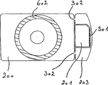
In Fig. 6, shown another kind of method.In this case, CD 200 has circle 601, and comprises two detachable module 201,201 '.This detachable module 201,201 ' is connected to CD 200 along broken line by groove 301,301 ', and 204 is surrounded at interval by opening in addition.
In Fig. 6, the road 602 of CD 200 is subjected to module 201, the 201 ' restriction that is provided with.On the contrary, in the embodiment shown in Fig. 2 and Fig. 3, road 602 is by the peripheral size restriction of CD 200.
An embodiment has been shown in Fig. 7 a, and wherein detachable module 201 one of is similar in by the disclosed embodiment shown in the International Patent Application WO that transfers Orga 01/18750 of Like invention with respect to the position class in the road 602 of CD 200.If the position of sim module is subjected to the requirement of ISO7810 standard, the road 602 of CD 200 is by external diameter 703 restrictions, and this external diameter is limited by sim module.For the standard plate driver that is used to read CD-ROM, give and be used to read 602 minimum diameter 704, the interval between internal diameter 704 and the external diameter 703 almost can be ignored, and does not in fact stay the space of data storage.Therefore, if according to the ISO standard 7810, this embodiment is unsuitable for the CD-ROM drive or the standard music CD driver of standard.
Yet, has an advantage at the embodiment shown in Fig. 7 a with respect to the publication that L ü ke transfers the International Patent Application WO 01/18750 of Orga, because the diameter 702 of CD 200 is at least 80mm, the diameter of this CD does not hinder the readability in the standard plate reading unit like this.
If the setting of SIM plug-in unit is not strictly corresponding to the ISO7810 standard, this SIM plug-in unit 201 can be arranged on the edge, shown in Fig. 7 b.Like this, this SIM plug-in unit 201 does not limit the road 602 of CD 200.In the figure, the hollow 706 that is used for electronic circuit also as seen, even the darker hollow 707 that is used for glue is also as seen.
Meet the ISO7810 standard at CD together with detachable module, have under the situation of width of the length of 85.6mm and 53.9mm, certain embodiment as shown in Figure 8 confirms it is that very big advantage is arranged.Shown detachable module 201 is SIM plug-in units, and it has electronic circuit 701, and the ISO7816 standard is satisfied in its position.Therefore, this sim module 201 is connected to CD 200 like this, make existing standard machine can be used for electronic circuit 701 be placed into sim module 201 in aerial.This has just reduced the production cost that has the CD 200 of sim module 201 according to of the present invention.Yet though the position of electronic circuit is correct, the design of connector has changed, because compare with normal structure, SIM plug-in unit 201 has rotated 180 degree, wherein figure 7 illustrates normal structure, in other words, the deflection border 801 of SIM plug-in unit is in the face of leaving the CD place.By existing standard machine only being made modification a little, just can obtain this different design by them, such modification is more much smaller than changing being provided with of module 201 itself.
Because stability, this SIM plug-in unit is surrounded by three grooves 301 that are used for broken line.
As shown in Figure 8, for the user of CD, the setting of this sim module 201 is still for the road 602 of CD has stayed enough spaces, so that comprise enough data.
The embodiment of Fig. 8 means that further the diagonal line 702 of CD 200 is at least 80mm, and it guarantees that CD 200 can play in all corresponding standard reading units like this.
Fig. 2,3,6,7 and embodiment shown in Figure 8 in, the position of microelectronic modules 200 is positioned at common circular CD-ROM and the periphery 601 of DVD, therefore, this microelectronic modules 200 is positioned at CD-ROM or the acceptable maximum gauge 12cm of DVD reading unit.Such CD-ROM or DVD read after can or separating before microelectronic modules is separated.For example, the user can be used for reading the information of CD in its reading unit before the SIM plug-in unit 201 that mobile phone is installed separates.Under these circumstances, SIM plug-in unit 201 was used in the actual decision of user in its phone before, the user can study the information on the CD 200.After SIM plug-in unit 201 separated, in case this SIM plug-in unit 201 is inserted in the mobile phone, the user still can read the information relevant with installing and be provided with phone.
For the user, want to read information at him, whether he is actual is wanted to buy under the situation of this module 201 so that find out, so in microelectronic modules 201, before for example SIM plug-in unit or another computer module separated, the information that can read on the CD 201 was very important.On the other hand, for the user, under the very important situation of this information during his installed module 201, wherein installing may be a lot of difficult steps, and after microelectronic modules 201 was separated, the information that can read was very important so.
Fig. 9 has shown another embodiment of CD, and it is for having the support card of CD 200 and two detachable module 201 and 201 ', and this detachable module for example can be the microelectronic modules as the SIM plug-in unit.One of module 201 is positioned within the periphery 601 that is generally used for circular CD-ROM, therefore be positioned within the acceptable maximum gauge of CD-ROM reading unit, and other microelectronic modules 201 ' part is positioned at outside the periphery 601 that is generally used for circular CD-ROM, and is positioned at outside the acceptable maximum gauge of CD-ROM reading unit.In order in CD-ROM drive, to read CD 200, be necessary to remove second microelectronic modules 201 '.After having bought CD 200, the user wants it is returned under the situation of dealer, for dealer, and the easy control of the safety whether this second microelectronic modules can have been read as CD-ROM200.
Because embodiment shown in Figure 8 has had the frame above the CD of arm's length standard, the production of such embodiment may require the modification of existing mould device.
Can form and have multiple difform CD 200, for example polygon, star or ellipse, when the user visited the local of dealer and must select in a plurality of providing, these various shapes can cause user's attention.
In Fig. 9, a detachable module 201 ' is connected to the support card with CD 200 by bridge 301.Perhaps, this detachable module 201 ' can be connected to CD along one or several perforated lines.Such bridge 301 or perforated lines can be produced by above-mentioned jumper bar principle, but also can construct this embolus 108 in die cavity 104, can avoid jumper bar like this.
Claims (15)
1. method that is used to produce the CD with detachable module, it comprises
-provide the mould with die cavity, this die cavity to have the inside dimension of size that has the CD of this detachable module corresponding to this, described mould have be used for will fusing polymkeric substance be fed to the feeding mechanism of die cavity,
-in die cavity, provide pressing mold, described pressing mold to have towards the surface of die cavity inside, described surface has and the corresponding surface structure of the corresponding surface structure of molding optical disks,
-polymkeric substance of fusing is fed in the die cavity, the polymkeric substance of described fusing is filled the remaining space in this die cavity,
-polymkeric substance is cooled to the temperature of its sclerosis,
-and shift out this molded CD,
It is characterized in that: this method comprises
-at least one stria generator is provided, be used for limiting the thickness of CD with detachable module along at least one broken line between this CD and this detachable module.
2. the method for claim 1, it is characterized in that: described method also comprises provides at least one module thickness limiter, be used to be limited in the thickness of the detachable module at least one zone, be preferably in 0.8mm between the 0.85mm, this zone is intended to selectively comprise electronic circuit.
3. as claim 1 or 2 described methods, it is characterized in that: described provide to have corresponding to this mould of inside dimension of size with CD of this detachable module comprise the standard mould that is provided for standard optical disc, and provide the embolus that can insert described standard mould, described embolus restriction in the described standard mould be used to the to be shaped inside dimension of die cavity of CD makes its size with the CD of standard different.
4. as any described method among the claim 1-3, it is characterized in that: described at least one stria generator comprises at least one movably jumper bar, and after having supplied described melt polymer, and before the sclerosis of described polymkeric substance, this method comprises described at least one jumper bar is moved into this die cavity.
5. as any described method among the claim 1-4, it is characterized in that: described method also is included in during described CD molded, described detachable module with the hollow that is used for electronic circuit is provided, and after described dish removes, be provided for electronic circuit is inserted the standard production machine of described hollow.
6. as any described method among the claim 1-5, it is characterized in that: after molded, this CD is provided with the reflection horizon, and covers by spraying coating, ink jet coatings, serigraphy or offset printing.
7. injection mold device that is used for having the CD of detachable module with polymeric material production, described injection mold device comprises:
-having the mould of first and second mould parts, this mould part can move between the opening and closing position mutually, and between these mould parts, under off-position, define die cavity, the polymkeric substance of fusing injects this die cavity, to form the dish that this has detachable module
Pressing mold in the-die cavity has towards the surface of the inside in chamber, and described surface has the corresponding surface structure of corresponding surface structure with molding optical disks,
It is characterized in that: described injection mold device also comprises:
-at least one stria generator is used for limiting along at least one broken line between this CD and this detachable module thickness of the CD with detachable module.
8. injection mold device as claimed in claim 7 is characterized in that: described device also comprises the module thickness limiter, is used to limit the thickness of detachable module, is preferably in 0.8mm between the 0.85mm, and described module is intended to selectively be used to hold electronic circuit.
9. as claim 7 or 8 described injection mold devices, it is characterized in that: described mould is the standard mould that is used for standard optical disc, and wherein said injection mold device also comprises the embolus that can insert described standard mould, described embolus restriction in the described standard mould be used to the be shaped inside dimension in chamber of CD with detachable module makes its size with the CD of standard different.
10. as any described injection mold device in the claim 7,8 or 9, it is characterized in that: described at least one stria generator is included at least one and is preferably on the direction that approaches vertical described CD in the jumper bar in the removable chamber that enters mould, and after melt polymer being fed to the chamber, and before described polymkeric substance sclerosis, described stria generator is intended to be moved in the chamber of this mould.
11. any described injection mold device as among the claim 7-10 is characterized in that: described stria generator is set to have tilted shape less than the oblique angles of 15 degree towards module and/or CD, preferably less than 12 degree.
12. any described injection mold device as among the claim 7-11 is characterized in that: described stria generator is set to have towards leaving the oblique angle of module greater than 8 degree, more preferably greater than 10 degree, especially is preferably greater than 12 degree.
13. any described injection mold device as among the claim 7-12 is characterized in that: big towards the oblique angle of described module towards the described oblique angle ratio that leaves described module.
14. the embolus that can be inserted into the standard mould with the chamber that is used for molded standard optical disc, the described embolus restriction in the described standard mould is used to form the inside dimension in the chamber of the CD with detachable module, makes them different with standard optical disc.
15. composition with CD of separable SIM plug-in unit, it is characterized in that: said composition has the length of about 85.6mm and the width of about 54mm, wherein this SIM plug-in unit is positioned at the position corresponding to the ISO7810 standard, and the deflection boundary surface of this SIM plug-in unit is to leaving CD.
Applications Claiming Priority (2)
| Application Number | Priority Date | Filing Date | Title |
|---|---|---|---|
| DKPA200100297 | 2001-02-22 | ||
| DKPA200100297 | 2001-02-22 |
Publications (1)
| Publication Number | Publication Date |
|---|---|
| CN1527760A true CN1527760A (en) | 2004-09-08 |
Family
ID=8160285
Family Applications (1)
| Application Number | Title | Priority Date | Filing Date |
|---|---|---|---|
| CNA028086929A Pending CN1527760A (en) | 2001-02-22 | 2002-02-22 | Method for producting of an optical disc with a detachable module |
Country Status (7)
| Country | Link |
|---|---|
| US (1) | US20060187805A1 (en) |
| EP (1) | EP1361944A1 (en) |
| JP (1) | JP2004522624A (en) |
| CN (1) | CN1527760A (en) |
| BR (1) | BR0207501A (en) |
| PL (1) | PL365289A1 (en) |
| WO (1) | WO2002066226A1 (en) |
Cited By (1)
| Publication number | Priority date | Publication date | Assignee | Title |
|---|---|---|---|---|
| CN105377515A (en) * | 2013-07-01 | 2016-03-02 | 欧贝特科技公司 | Production of high thickness plate comprising detachable low thickness card |
Families Citing this family (11)
| Publication number | Priority date | Publication date | Assignee | Title |
|---|---|---|---|---|
| EP1380990A1 (en) * | 2002-07-09 | 2004-01-14 | SCHLUMBERGER Systèmes | Data carrier being removably mounted on other data carrier of different type |
| KR20050059215A (en) * | 2002-09-30 | 2005-06-17 | 코닌클리케 필립스 일렉트로닉스 엔.브이. | Record carrier with multiple coupling elements |
| JP2006501588A (en) * | 2002-09-30 | 2006-01-12 | コーニンクレッカ フィリップス エレクトロニクス エヌ ヴィ | Record carrier with multiple embedded chips |
| FR2860321B1 (en) * | 2003-09-29 | 2006-01-13 | Oberthur Card Syst Sa | MICROCIRCUIT CARD IN SEVERAL PARTS |
| EP1626365A1 (en) * | 2004-08-10 | 2006-02-15 | Axalto SA | A multi-standards compliant card body |
| FI20051120A0 (en) * | 2005-02-23 | 2005-11-04 | Fortion Designit Oy | Workpiece containing removable optical products and process for making them |
| EP1903480A1 (en) * | 2006-09-22 | 2008-03-26 | Axalto SA | Portable device comprising two separable data supports utilisable by two different readers, and manufacturing process |
| JPWO2008038428A1 (en) * | 2006-09-27 | 2010-01-28 | 株式会社ルネサステクノロジ | IC card and IC card socket |
| US8234667B2 (en) * | 2008-01-04 | 2012-07-31 | International Business Machines Corporation | Disk with embedded flash memory and disc drive |
| EP2568418B1 (en) * | 2011-09-12 | 2015-08-19 | Oberthur Technologies | A microcircuit card and a tool and method for making such a card |
| FR2985345B1 (en) * | 2011-12-29 | 2021-11-26 | Oberthur Technologies | PROCESS FOR MANUFACTURING A SMALL THICKNESS CARD DETACHABLE FROM A LARGE THICKNESS PLATE |
Family Cites Families (8)
| Publication number | Priority date | Publication date | Assignee | Title |
|---|---|---|---|---|
| NL8701499A (en) * | 1987-06-26 | 1989-01-16 | Philips Nv | SYRINGE DEVICE FOR MANUFACTURING PLASTICS INFORMATION PLATES AND METHOD FOR MANUFACTURING SYNTHETIC PLATES WITH A SYRINGE DEVICE. |
| JPH03254919A (en) * | 1990-03-06 | 1991-11-13 | Takata Kk | Manufacture of module cover of air bag |
| DK0584143T3 (en) * | 1991-05-10 | 1996-02-12 | Gao Ges F | Method and apparatus for making plastic moldings with areas of reduced thickness |
| US5776522A (en) * | 1996-04-29 | 1998-07-07 | Larry J. Winget | Apparatus for making an air bag cover having a hidden tear seam |
| DE29817857U1 (en) * | 1998-08-05 | 1998-12-24 | Frey Werner | Device for the production of shaped CDs |
| WO2000071323A1 (en) * | 1999-05-26 | 2000-11-30 | Iaccess.Com, L.C. | System and method for manufacturing specially shaped cd-roms utilizing injection molding |
| DE19943092A1 (en) * | 1999-09-09 | 2001-03-15 | Orga Kartensysteme Gmbh | Data carrier with semiconductor circuit and detachable optical storage medium |
| DE20102719U1 (en) * | 2001-02-07 | 2001-05-23 | C U B A Media Und Entertainmen | Chip card, in particular SIM card with carrier element |
-
2002
- 2002-02-22 BR BR0207501-6A patent/BR0207501A/en not_active IP Right Cessation
- 2002-02-22 EP EP02700183A patent/EP1361944A1/en not_active Withdrawn
- 2002-02-22 CN CNA028086929A patent/CN1527760A/en active Pending
- 2002-02-22 PL PL02365289A patent/PL365289A1/en unknown
- 2002-02-22 JP JP2002565767A patent/JP2004522624A/en active Pending
- 2002-02-22 WO PCT/DK2002/000122 patent/WO2002066226A1/en not_active Application Discontinuation
- 2002-02-22 US US10/468,481 patent/US20060187805A1/en not_active Abandoned
Cited By (2)
| Publication number | Priority date | Publication date | Assignee | Title |
|---|---|---|---|---|
| CN105377515A (en) * | 2013-07-01 | 2016-03-02 | 欧贝特科技公司 | Production of high thickness plate comprising detachable low thickness card |
| CN105377515B (en) * | 2013-07-01 | 2017-11-10 | 欧贝特科技公司 | Make the Method and kit for of the big thick plates for the separable card for including small thickness |
Also Published As
| Publication number | Publication date |
|---|---|
| WO2002066226A1 (en) | 2002-08-29 |
| PL365289A1 (en) | 2004-12-27 |
| BR0207501A (en) | 2004-03-09 |
| JP2004522624A (en) | 2004-07-29 |
| EP1361944A1 (en) | 2003-11-19 |
| US20060187805A1 (en) | 2006-08-24 |
Similar Documents
| Publication | Publication Date | Title |
|---|---|---|
| CN1527760A (en) | Method for producting of an optical disc with a detachable module | |
| CN206698309U (en) | Camera module and its molding photosensory assembly and mould | |
| CN206302476U (en) | Camera module and its molded circuit board component and mould and electronic equipment | |
| CN1214344C (en) | Method for making electronic module or label, resulting electronic module or label and medium containing such a module or label | |
| CN101184608B (en) | System, device, and method for producing thin plastic lenses | |
| CN1299314A (en) | Method for makign tamper-preventing, contact-type, smart cards | |
| CN107682591A (en) | Camera module and its molding photosensory assembly and manufacture method | |
| CN1664624A (en) | Lens, transmission screen, and method for manufacturing the lens | |
| CN1655265A (en) | Method of manufacturing optical information recording medium | |
| CN100437150C (en) | Micro mirror and method of manufacturing the same | |
| US20110133364A1 (en) | Method for Manufacturing Micro-Channel, Die for Molding Micro-Channel Chip, and Micro-Channel Chip | |
| CN1675596A (en) | Fluid containment substrates for holographic media | |
| CN1319842A (en) | Compact disc and substrate and moulding metal die thereof | |
| CN107682592A (en) | Camera module and its molded circuit board component and manufacture method | |
| US8749863B2 (en) | Plastic article, method of shaping plastic article, and optical scanning device having plastic article | |
| EP1245363A1 (en) | Stamper, mold system, recording medium substrate, recording medium, optical disc substrate, optical disc, and method for producing stamper | |
| US20020185760A1 (en) | Disk molding apparatus and disk substrate manufacturing method | |
| CN101630686B (en) | Solid-state imaging apparatus and case for containing solid-state imaging device | |
| CN100550983C (en) | Solid-state imager housing, its manufacture method and solid camera head | |
| WO2004097488A1 (en) | Method of manufacturing hybrid aspherical lens | |
| CN2703635Y (en) | Forming mould for CD substrate | |
| CN1308945C (en) | Method for manufacturing discoid optical record medium and discoid optical record medium | |
| JPH0572494A (en) | Rotary polygon mirror made of plastic and its manufacture | |
| CN1747017A (en) | Optical information recording medium | |
| JP4973141B2 (en) | Manufacturing method of card with display function |
Legal Events
| Date | Code | Title | Description |
|---|---|---|---|
| C06 | Publication | ||
| PB01 | Publication | ||
| C10 | Entry into substantive examination | ||
| SE01 | Entry into force of request for substantive examination | ||
| C02 | Deemed withdrawal of patent application after publication (patent law 2001) | ||
| WD01 | Invention patent application deemed withdrawn after publication |