CN1310350C - Seal for an electrochemical cell - Google Patents
Seal for an electrochemical cell Download PDFInfo
- Publication number
- CN1310350C CN1310350C CNB038040867A CN03804086A CN1310350C CN 1310350 C CN1310350 C CN 1310350C CN B038040867 A CNB038040867 A CN B038040867A CN 03804086 A CN03804086 A CN 03804086A CN 1310350 C CN1310350 C CN 1310350C
- Authority
- CN
- China
- Prior art keywords
- seal
- exhaust section
- electrochemical cell
- cell according
- recess
- Prior art date
- Legal status (The legal status is an assumption and is not a legal conclusion. Google has not performed a legal analysis and makes no representation as to the accuracy of the status listed.)
- Expired - Fee Related
Links
Images


Classifications
-
- H—ELECTRICITY
- H01—ELECTRIC ELEMENTS
- H01M—PROCESSES OR MEANS, e.g. BATTERIES, FOR THE DIRECT CONVERSION OF CHEMICAL ENERGY INTO ELECTRICAL ENERGY
- H01M50/00—Constructional details or processes of manufacture of the non-active parts of electrochemical cells other than fuel cells, e.g. hybrid cells
- H01M50/10—Primary casings, jackets or wrappings of a single cell or a single battery
- H01M50/147—Lids or covers
- H01M50/148—Lids or covers characterised by their shape
- H01M50/154—Lid or cover comprising an axial bore for receiving a central current collector
-
- H—ELECTRICITY
- H01—ELECTRIC ELEMENTS
- H01M—PROCESSES OR MEANS, e.g. BATTERIES, FOR THE DIRECT CONVERSION OF CHEMICAL ENERGY INTO ELECTRICAL ENERGY
- H01M50/00—Constructional details or processes of manufacture of the non-active parts of electrochemical cells other than fuel cells, e.g. hybrid cells
- H01M50/10—Primary casings, jackets or wrappings of a single cell or a single battery
- H01M50/147—Lids or covers
- H01M50/148—Lids or covers characterised by their shape
- H01M50/152—Lids or covers characterised by their shape for cells having curved cross-section, e.g. round or elliptic
-
- H—ELECTRICITY
- H01—ELECTRIC ELEMENTS
- H01M—PROCESSES OR MEANS, e.g. BATTERIES, FOR THE DIRECT CONVERSION OF CHEMICAL ENERGY INTO ELECTRICAL ENERGY
- H01M50/00—Constructional details or processes of manufacture of the non-active parts of electrochemical cells other than fuel cells, e.g. hybrid cells
- H01M50/10—Primary casings, jackets or wrappings of a single cell or a single battery
- H01M50/183—Sealing members
- H01M50/19—Sealing members characterised by the material
- H01M50/193—Organic material
-
- H—ELECTRICITY
- H01—ELECTRIC ELEMENTS
- H01M—PROCESSES OR MEANS, e.g. BATTERIES, FOR THE DIRECT CONVERSION OF CHEMICAL ENERGY INTO ELECTRICAL ENERGY
- H01M50/00—Constructional details or processes of manufacture of the non-active parts of electrochemical cells other than fuel cells, e.g. hybrid cells
- H01M50/30—Arrangements for facilitating escape of gases
- H01M50/317—Re-sealable arrangements
- H01M50/325—Re-sealable arrangements comprising deformable valve members, e.g. elastic or flexible valve members
-
- Y—GENERAL TAGGING OF NEW TECHNOLOGICAL DEVELOPMENTS; GENERAL TAGGING OF CROSS-SECTIONAL TECHNOLOGIES SPANNING OVER SEVERAL SECTIONS OF THE IPC; TECHNICAL SUBJECTS COVERED BY FORMER USPC CROSS-REFERENCE ART COLLECTIONS [XRACs] AND DIGESTS
- Y02—TECHNOLOGIES OR APPLICATIONS FOR MITIGATION OR ADAPTATION AGAINST CLIMATE CHANGE
- Y02E—REDUCTION OF GREENHOUSE GAS [GHG] EMISSIONS, RELATED TO ENERGY GENERATION, TRANSMISSION OR DISTRIBUTION
- Y02E60/00—Enabling technologies; Technologies with a potential or indirect contribution to GHG emissions mitigation
- Y02E60/10—Energy storage using batteries
Abstract
A ventable seal is provided for closing the open end of an electrochemical cell. The seal incorporates indentations formed in the outer surface of the centrally located hub that abuts a flexible diaphragm at a ventable interface. If a cell's internal pressure reaches an unsafe level and the seal ruptures, the indentations prevent resealing of the ruptured seal thereby avoiding a second build up of pressure within the cell.
Description
Technical field
But the present invention relates generally to the seal of the exhaust that is used for pressure vessel, but relates more specifically to be used for the seal of the exhaust of electrochemical cell.
Background technology
Electrochemical cell such as cylindrical alkaline electrochemical cell have adopted two kinds of electrochemical active materials and a kind of aqueous electrolyte.Electrochemical active material is manganese dioxide and zinc normally.These materials are contained in the elongated hydrostatic column usually, and this container at one end opens wide, and makes electrochemical active material and electrolyte to be inserted in wherein in the production process of battery.Closure assemblies has sealed the openend of container, and this assembly includes the elastic sealing element of dish type and passes the center of sealing part and the long and thin metal current-collector stretched.Seal generally includes the core (hub) round current-collector, and the interior thin membrane of middle section that is integrally molded in seal.The function of barrier film is to break when internal pressure is too high, and discharges gas in battery.Current-collector provides zinc and the conductive path between an end cover for battery cells at place, battery end.
The manufacturer of electrochemical cell is making great efforts to improve their performance of product in many kinds of battery powdered devices always.Because most of batteries use in a conventional manner, therefore having only seldom, the battery of part is under the state abominable or abuse.Wherein a kind of abuse state takes place when battery has produced direct short-circuit.This state takes place when being to have formed the low-resistance electric pathway between anode and the negative electrode.In one case, when device as comprise contact spring in the flashlight of two D batteries connected unintentionally battery the steel vessel that contacts with negative electrode the edge and and the negative pole end cap that electrically contacts of anode between the gap time, direct electrical short will take place.Spring is made by high conductivity material such as nickel-plated steel, therefore can provide low-resistance to be electrically connected between anode and negative electrode.In case formed direct electrical short, battery will discharge as quickly as possible.In highly being about the D battery that 61 millimeters and diameter be about 35 millimeters, may there be the electric currents that surpass 20 peaces.Owing to heat-producing chemical reaction has taken place, so entire cell can reach the temperature above 70 ℃ in battery in the repid discharge process.The rising of temperature makes the pressure in the battery increase.Except making the battery intensification, the chemical reaction that takes place in discharge process has also promptly produced a large amount of hydrogen, and this has just increased the pressure in the battery significantly.Effect has caused the elastomeric seal deliquescing of being made by nylon usually in the time of hydrogen generation and temperature rise, and loses its part-structure rigidity.Because being heated and the increase of internal pressure of nylon, but the thin discharge portion of seal may become elongated.Therefore, when the seal of deliquescing and distortion breaks in response to pressure raises, the gas that just has certain primary quantity is overflowed in battery, but when softening rupture seal part contacted and reseal on core with the smooth outer surface of seal core, the crack in the rupture seal part can be resealed.If the rupture seal part reseals really on core and battery continues to produce gas, battery finally can produce to curl and discharge (crimp release), wherein curling between seal and the container is connected destroyedly, and closure assemblies is forced to from container and ejects.
As disclosed among U.S. Pat 6270919 B1, attempted before to prevent that the trial that the rupture seal part reseals from comprising that the inside disc-shaped part that improves seal is to make it to include rib.Rib is designed to keep the opening in the rupture seal part, thereby prevents resealing of exhaust gear.Yet, although being included in, rib helps to prevent that most of batteries from forming reseals in the barrier film of seal, yet can deform during the heat that some batteries that are combined with rib are produced during affording direct electrical short, make rib after seal ruptures, can not keep the opening in the seal.
In the seal designs in being disclosed in U.S. Pat 6312850 B1, be provided with vertical groove in the surface of the compression piece in a part that has formed black box.But groove design becomes can prevent the seal barrier film generation of exhaust and reseals.Groove has formed the passage that allows gas to discharge, thereby can prevent resealing of exhaust barrier film.Although this embodiment has prevented resealing of vent closure really, however compression piece be one must be manufactured and be assembled in optional feature on the seal.This has increased battery cost, and makes the manufacturing process of battery complicated.And compression piece has occupied the constant volume in the battery, and this volume can be used to hold electrochemical active material originally better.
Therefore, need a kind of cost lower and make simple elastic sealing element, it has only occupied a small amount of volume in the battery, but and the resealing of electrochemical cell that can prevent exhaust reliably.
Summary of the invention
But the invention provides a kind of seal of exhaust, it can prevent that the rupture seal part generation in the pressure vessel from resealing.Disc shaped seal body manufactures single parts, and it comprises first surface, second surface, is formed at the flexible partition between these surfaces, and the projection of stretching from first surface.This projection comprises proximal segment and exhaust section.Proximal segment has formed ventable interface with the flexible partition adjacency and with flexible partition, and comprises the outer surface of no one or more recesses.Exhaust section and proximal segment are provided with and adjacency with it with one heart, and comprise and have the outer surface that at least one is formed at recess wherein.Recess in the exhaust section has formed the expedite passage along the exhaust section outer surface.
The present invention also provides a kind of electrochemical cell that has container, and this container has openend, blind end and is in sidewall between them.Container comprises dividing plate and is arranged on two kinds of electrochemical active materials of the opposite side of dividing plate.The disc shaped seal body that forms single parts is fixed on the openend of container.Seal have end face, bottom surface and with the contacted periphery of end face and bottom surface.Flexible partition is formed between these surfaces, and is provided with round the projection that is in the center, this projection from the central vertical of seal end face stretch.This projection is formed with the opening between end face and the bottom surface.This projection have with flexible partition in abutting connection with and formed the proximal segment of ventable interface with flexible partition, and be provided with one heart with proximal segment and the exhaust section of adjacency with it.Proximal segment comprises the outer surface of no one or more recesses.Exhaust section comprises and has the outer surface that at least one is formed at recess wherein.Recess in the exhaust section has formed the expedite buck channel along the exhaust section outer surface.Current-collector extends through the opening in the projection, and contacts with electrochemical active material in the battery.Between the external environment condition of flexible partition and battery, be provided with lid.
Description of drawings
Fig. 1 is the cutaway view of traditional cylindrical alkaline electrochemical cell;
Fig. 2 is the perspective view of seal of the present invention;
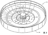
Fig. 3 is the perspective view of another seal of the present invention;
Fig. 4 is the cutaway view of seal shown in Figure 2; With
Fig. 5 is the partial sectional view of electrochemical cell of the present invention.
Embodiment
Refer now to accompanying drawing and, shown the section of traditional alkali electrochemical battery 90 among the figure more specifically referring to Fig. 1.The parts of battery are followed successively by container 10, adjacent to first electrode 50 of the inner surface of container 10, with the inner surface 56 contacted dividing plates 20 of first electrode 50, be located at by second electrode 60 in the dividing plate 20 formed cavitys, and be fixed on closure assemblies 70 on the container 10.Container 10 has openend 12, blind end 14 and the sidewall between them 16.Blind end 14, sidewall 16 and closure assemblies 70 have formed a cavity, and the electrode of battery promptly is contained in wherein.
Seal of the present invention as shown in Figure 2.Can make seal by injection-molded non-conductive material such as nylon, polystyrene, polypropylene or other plastic materials.Mold design becomes to can be seal provides required feature, for example rupturable steam vent and the opening that is positioned at the center that is used to hold current-collector, and this makes that seal is adapted at using in the electrochemical cell.As shown in Figure 2, seal 100 is parts of dish type roughly, the edge 106 that it has first surface 102, second surface 104 and has formed the seal periphery.First surface 102 is referred to herein as end face.Second surface 104 is referred to herein as the bottom surface.Edge 106 comprises upstanding wall 108.The central area 110 of seal 100 is arranged on the inside of wall.This central area comprises the flexible partition 112 with ventable interface 126 adjacency.Ventable interface contacts with the projection of vertically stretching from the center of seal end face 114.Projection is also referred to as core in this article.The non-discharge portion 116 of central area 110 is between wall 108 and flexible partition 112.Non-discharge portion is than thicker round the flexible partition 112 of core 114.
To introduce the function of proximal segment, exhaust section and the distal ports of projection below.Proximal segment 115 has formed ventable interface 126 with flexible partition 112.This INTERFACE DESIGN becomes will break when the internal pressure of battery reaches predetermined value.Ventable interface 126 preferably can promptly be torn when the seal exhaust.In order to realize predictable quick exhaust, proximal segment 115 and flexible partition 112 should form the ventable interface 126 of an arc, and it has homogeneous thickness around proximal segment.By being provided with and the thin adjacent washer shaped proximal section of ventable interface, just can realize this segmental arc.This segmental arc is preferably at least 180 °, and better is 270 °, preferably a circle.The height of proximal segment must be chosen to guarantee that the one or more recesses in the exhaust section can not disturb breaking of 126 places, interface.
The critical function of exhaust section provides one or more recesses, the step-down path when it discharges from battery as internal gas.Although can change length, the width of recess and highly regulate for example factors such as plasticity of seal, yet the ratio of the width of preferred recess and the degree of depth is about 3: 1.The recess of especially preferred arc, this is because arc is attached in the mould that is used to form seal easily.And arc-shaped notch helps as one man to make seal.The height of recess must be enough to allow gas to escape in the external environment condition of battery.
The major function of distal ports 119 is that leakproof interface (see figure 5) is provided between current-collector 276 and inner cap 150.Interface between current-collector and the inner cap must be able to stop electrolyte by leaving battery along spreading of current-collector surface.This can realize so that form interference fit between current-collector and seal greater than the current-collector of the internal diameter of the opening in the seal 100 122 by using external diameter.In order to realize compression uniformly on the distal ports between current-collector and the inner cap, the thickness of distal ports between these two parts must be consistent.Therefore, must end under the distal ports as one or more recesses of the feature of exhaust section, like this, recess just can not hinder the compression of the seal in the distal ports 119 of projection 114.
As shown in Figure 2, one or more ribs 148 can be attached in the end face of flexible partition 112.One end of each rib 148 is adjacent to the outer surface of proximal segment 115.Each rib is integrally formed in the end face 102 of seal 100, and along from the center of seal 100 towards the emanant line segment of seal periphery and locate.One end each rib 148 and that the core proximal segment is adjacent is roughly between the recess in the exhaust section 117 of projection 114.Rib 148 is intended to prevent that flexible partition 112 from resealing on the inner surface of inner cap 150.Because rib has prevented the part of torn flexible diaphragm and has moved upward and blocked the effusion path of the gas that is trapped in the battery that therefore the seal that breaks can not reseal, and does not allow battery supercharging once more.
Fig. 3 has shown another embodiment of the present invention.Seal 101 be dish type and form single parts, it has first surface 102, second surface 104 and periphery 106.Flexible partition 112 is formed between first surface and the second surface.Projection 114 is stretched from first surface 102, and adjacent at ventable interface 126 places and flexible partition 112.Projection 114 comprises proximal segment 115 and exhaust section 117.The surface of proximal segment 115 is without any groove, recess or passage.On the contrary, the surface of exhaust section 117 comprises at least one recess.As shown in Figure 3, core can have several recesses 128,130,132 and 138.The quantity that can change recess is regulated the difference of the physical parameter of seal, such as: the external diameter of seal core; The elasticity of encapsulant under elevated temperature; But and the pressure of seal designs when becoming exhaust.Core preferably has two, four or six recesses.Between any two adjacent recesses, be provided with the part 140 of outside protrusion.Each recess that the part that should outwards protrude will be also referred to as the step-down path in this article separates each other.
Fig. 4 has shown the section of seal shown in Figure 2.Projection 114 comprises proximal segment 115, exhaust section 117 and distal ports 119.Proximal segment 115 is adjacent to flexible partition 112 at ventable interface 126 places.The surface of proximal segment 115 is without any groove or recess.Exhaust section 117 comprises recess 130 and part 140 (not shown) that outwards protrude.Distal ports 119 is provided with one heart with proximal segment 115 and exhaust section 117, and links to each other with exhaust section 117.The free end of projection 114 ends at shoulder 120 places.Opening 122 at the seal center defines the passage between end face 102 and the bottom surface 104.Periphery 106 is limited by wall 108.Flange 152 is adjacent on the wall 108.Rib 148 extends out from the surface of flexible partition 112.
Fig. 5 has shown the partial sectional view of electrochemical cell 200 of the present invention.Battery comprises the container 210 with openend 212.In container, be provided with first electrode 250, second electrode 260, dividing plate 220 and a certain amount of aqueous alkaline electrolyte.Closure assemblies 270 is fixed on the openend of container.This assembly comprises seal 100, it is included in the proximal segment 115 of ventable interface 126 places and flexible partition 112 adjacency, adjacent and include the exhaust section 117 of recess 130 and 132 with proximal segment 115, and distal ports 119 concentric with exhaust section 117 and that be attached thereto.Closure assemblies also comprises the current-collector 276 at the center of being arranged on, and it is outstanding and pass opening 122 and inner cap 150 in the seal 100.Current-collector is the elongated rods of being made by electric conducting material such as brass.One end of current-collector contacts with second electrode 260, and the other end of current-collector is outstanding and pass the end face 102 of seal 100, and touches an end cap 158 of battery.Inner cap 150 is positioned on the end face 102 of seal 100.The periphery of inner cap 150 contacts with the flange of seal 152.The center of inner cap 150 is formed with opening 154.The internal diameter of interior cover gab 154 is less than the external diameter of core exhaust section 117, but greater than the external diameter of core distal ports 119.After the thickness of the internal diameter of the external diameter of current-collector 276, opening 122 and distal ports 119 is chosen to make in the opening 122 that current-collector 276 is inserted into seal 100, forcing the part of distal ports 119 outwards to move to by current-collector 276 leans against on the inner cap 150, thereby on the distal ports of seal, applied tangential tension, and formed interference fit between current-collector 276 and the distal ports 119 and between distal ports 119 and inner cap 150.The purpose that forms interference fit is to prevent that electrolyte from overflowing with the interface of core 114 along current-collector 276.Since distal ports 119 must be between current-collector 276 and inner cap 150 pressurized equably, the pressure relief indentations that therefore is arranged in core exhaust section 117 can not extend into distal ports.The gas that second opening 156 in the inner cap 150 allows to discharge via the crack in the seal is overflowed from the space that is limited by seal end face 102 and inner cap 150.Opening 160 in the end cap 158 allows the gas through opening 156 to leave end cap and enters into the external environment condition of battery.The end cap 158 that is positioned on the closure assemblies 270 electrically contacts with current-collector 276.
The electrolyte that is applicable to battery of the present invention is the potassium hydroxide aqueous solution of 37% weight.By a certain amount of liquid electrolyte being placed in the cavity that forms by first electrode, just electrolyte can be attached in the battery.By allowing the gelling medium to absorb the aqueous solution of potassium hydroxide, also electrolyte can be incorporated in the battery in the technology that is used for making second electrode.If electrolyte contacts with dividing plate 220 with first electrode 250, second electrode 260, the method that is used for electrolyte is attached to battery so is unimportant.
Above-mentioned introduction only is regarded as preferred embodiment.Concerning those skilled in the art and manufacturing or use the personnel of the present invention, the present invention is improved being easy to expect.Therefore, be appreciated that shown in the accompanying drawing and the embodiment that introduces hereinbefore only is used for illustration purpose, be not limited to scope of the present invention, scope of the present invention is limited according to Patent Law rule and doctrine of equivalents by claims.
Claims (33)
1. electrochemical cell comprises:
(a) container that has openend, blind end and be in the sidewall between them, described container comprise dividing plate and are arranged on the electrochemical active material of the opposite side of described dividing plate;
(b) be fixed on disc shaped seal body on the openend of described container, described seal forms single parts and has end face, the bottom surface and with the contacted periphery of described end face and bottom surface, flexible partition is formed between described end face and the bottom surface, and be provided with round the projection that is in the center, described projection from the central vertical of described end face stretch, and be formed with the opening between described end face and the bottom surface, described projection have with described flexible partition in abutting connection with and formed ventable interface with flexible partition and comprised the proximal segment of the outer surface of no one or more recesses, and be provided with one heart with described proximal segment and with it in abutting connection with and comprise and have the exhaust section that at least one is formed at the outer surface of recess wherein that the recess in the described exhaust section has formed the expedite buck channel along described exhaust section outer surface;
(c) extend through in the described projection described opening and can with the contacted current-collector of the electrochemical active material in the described battery; With
(d) be located at enclosing cover between the external environment condition of the flexible partition of described seal and described battery.
2. electrochemical cell according to claim 1 is characterized in that, described projection also comprises with described exhaust section and being provided with one heart and adjacent with it distal ports.
3. electrochemical cell according to claim 2, it is characterized in that, described battery also comprises the inner cap between described flexible partition and described enclosing cover, described inner cap comprises the hole at the center of being positioned at, the internal diameter in the described hole external diameter with described projection distal ports at least is the same big, and the distal ports of described projection is passed the centre bore of described inner cap and stretched.
4. electrochemical cell according to claim 3, it is characterized in that, described inner cap and described current-collector co-operation are to compress the part of described distal ports, greater than the internal diameter of described seal opening, therefore described current-collector can apply tangential tension to the part in compression of described distal ports before the external diameter of described current-collector was chosen in being inserted into described current-collector.
5. electrochemical cell according to claim 2 is characterized in that, the external diameter of described distal ports is less than the external diameter of described exhaust section, and the external diameter of described exhaust section is less than the external diameter of described proximal segment.
6. electrochemical cell according to claim 5 is characterized in that, described exhaust section on described projection and described distal ports formed shoulder at the interface.
7. electrochemical cell according to claim 1 is characterized in that described ventable interface has formed at least 180 ° segmental arc.
8. electrochemical cell according to claim 1 is characterized in that described ventable interface has formed at least 270 ° segmental arc.
9. electrochemical cell according to claim 1 is characterized in that, described ventable interface has formed a circle.
10. electrochemical cell according to claim 1 is characterized in that, the ratio of the width of described exhaust section recess and the degree of depth is at least greater than 1: 1 and less than 6: 1.
11. electrochemical cell according to claim 1 is characterized in that, the ratio of the width of described exhaust section recess and the degree of depth is greater than 2: 1 and less than 4: 1.
12. electrochemical cell according to claim 1 is characterized in that, described exhaust section recess is an arc.
13. electrochemical cell according to claim 1 is characterized in that, the outer surface of described exhaust section comprises at least two recesses.
14. electrochemical cell according to claim 1 is characterized in that, the outer surface of described exhaust section comprises at least four recesses.
15. electrochemical cell according to claim 1 is characterized in that, the outer surface of described exhaust section comprises at least six recesses.
16. electrochemical cell according to claim 13, it is characterized in that, described seal comprises at least one rib that is formed in the described flexible partition, described rib is adjacent to the proximal segment of described projection, and align towards the emanant line segment of the periphery of described seal with the center from described seal, between described at least two recesses of described rib in described exhaust section.
17. electrochemical cell according to claim 1 is characterized in that, described lid be conduction and contact with described current-collector.
18. electrochemical cell according to claim 1 is characterized in that, described seal is nonconducting.
19. electrochemical cell according to claim 18 is characterized in that, described seal comprises the material that is selected from nylon, polypropylene, polystyrene.
20. electrochemical cell according to claim 18 is characterized in that, described seal is made up of the material that is selected from nylon, polypropylene, polystyrene.
21. a disc shaped seal body that forms single parts that is used for pressure vessel comprises:
(a) first surface, second surface and be formed at flexible partition between the described surface; With
(b) be in the center and from the central vertical of described first surface the projection stretched, described barrier film is located round described projection, described projection have with described flexible partition in abutting connection with and formed ventable interface with flexible partition and comprised the proximal segment of the outer surface of no one or more recesses, and be provided with one heart with described proximal segment and with it in abutting connection with and comprise and have the exhaust section that at least one is formed at the outer surface of recess wherein that the recess in the described exhaust section has formed the expedite buck channel along described exhaust section outer surface.
22. seal according to claim 21 is characterized in that, described ventable interface has formed at least 180 ° segmental arc.
23. seal according to claim 21 is characterized in that, described ventable interface has formed at least 270 ° segmental arc.
24. seal according to claim 21 is characterized in that, described ventable interface has formed a circle.
25. seal according to claim 21 is characterized in that, the outer surface of described exhaust section comprises two or more recesses.
26. seal according to claim 21 is characterized in that, the outer surface of described exhaust section comprises four or more a plurality of recess.
27. seal according to claim 21 is characterized in that, the outer surface of described exhaust section comprises six or more a plurality of recess.
28. seal according to claim 21 is characterized in that, the ratio of the width of described exhaust section recess and the degree of depth was at least 1: 1 and less than 6: 1.
29. seal according to claim 21 is characterized in that, the ratio of the width of described exhaust section recess and the degree of depth was at least 2: 1 and less than 4: 1.
30. seal according to claim 21 is characterized in that, described exhaust section recess is an arc.
31. seal according to claim 21 is characterized in that, described seal is nonconducting.
32. seal according to claim 21 is characterized in that, described seal comprises the material that is selected from nylon, polypropylene, polystyrene.
33. seal according to claim 21 is characterized in that, described seal is made up of the material that is selected from nylon, polypropylene, polystyrene.
Applications Claiming Priority (2)
| Application Number | Priority Date | Filing Date | Title |
|---|---|---|---|
| US10/079,678 | 2002-02-20 | ||
| US10/079,678 US6737188B2 (en) | 2002-02-20 | 2002-02-20 | Seal for an electrochemical cell |
Publications (2)
| Publication Number | Publication Date |
|---|---|
| CN1633720A CN1633720A (en) | 2005-06-29 |
| CN1310350C true CN1310350C (en) | 2007-04-11 |
Family
ID=27733075
Family Applications (1)
| Application Number | Title | Priority Date | Filing Date |
|---|---|---|---|
| CNB038040867A Expired - Fee Related CN1310350C (en) | 2002-02-20 | 2003-01-29 | Seal for an electrochemical cell |
Country Status (8)
| Country | Link |
|---|---|
| US (1) | US6737188B2 (en) |
| EP (1) | EP1476910B1 (en) |
| JP (1) | JP4515770B2 (en) |
| CN (1) | CN1310350C (en) |
| AT (1) | ATE311668T1 (en) |
| AU (1) | AU2003209423A1 (en) |
| DE (1) | DE60302553T2 (en) |
| WO (1) | WO2003073532A2 (en) |
Families Citing this family (7)
| Publication number | Priority date | Publication date | Assignee | Title |
|---|---|---|---|---|
| EP1678769B1 (en) * | 2003-10-28 | 2011-09-28 | Johnson Controls Technology Company | Battery system with improved heat dissipation |
| US7579105B2 (en) * | 2005-02-18 | 2009-08-25 | The Gillette Company | End cap assembly and vent for high power cells |
| WO2007001345A2 (en) * | 2005-03-14 | 2007-01-04 | Johnson Controls Technology Company | Lithium battery system |
| ES2275419B1 (en) * | 2005-07-27 | 2008-04-16 | Celaya Emparanza Y Galdos, S.A. Cegasa | "SAFETY DEVICE IN STAIN CLOSURES OF ELECTROCHEMICAL BATTERIES". |
| KR100804703B1 (en) * | 2006-11-01 | 2008-02-18 | 삼성에스디아이 주식회사 | Apparatus for measuring electric and stack for fuel cell therewith |
| US20080166626A1 (en) * | 2007-01-05 | 2008-07-10 | Yoppolo Robert A | End cap seal assembly for an electrochemical cell |
| US20090226805A1 (en) * | 2008-03-07 | 2009-09-10 | Robert Yoppolo | Battery |
Citations (3)
| Publication number | Priority date | Publication date | Assignee | Title |
|---|---|---|---|---|
| JP2000003697A (en) * | 1998-06-15 | 2000-01-07 | Sony Corp | Gasket, forming method for gasket and cylindrical alkaline battery using gasket |
| CN1268253A (en) * | 1997-06-25 | 2000-09-27 | 永备电池有限公司 | A V-shaped gasket for galvanic cells |
| US6270919B1 (en) * | 1999-04-27 | 2001-08-07 | Eveready Battery Company, Inc. | Electrochemical cell having low profile seal assembly with anti-resealing vent |
Family Cites Families (4)
| Publication number | Priority date | Publication date | Assignee | Title |
|---|---|---|---|---|
| JPS61133552A (en) * | 1984-12-03 | 1986-06-20 | Fuji Elelctrochem Co Ltd | Sealed gasket for explosion-proof cell |
| JP2543325Y2 (en) * | 1991-01-14 | 1997-08-06 | ソニー株式会社 | Battery |
| JP2000195478A (en) * | 1998-12-24 | 2000-07-14 | Toshiba Battery Co Ltd | Cylindrical alkali battery |
| US6312850B1 (en) * | 1999-09-14 | 2001-11-06 | Eveready Battery Company, Inc. | Current collector and seal assembly for electrochemical cell |
-
2002
- 2002-02-20 US US10/079,678 patent/US6737188B2/en not_active Expired - Lifetime
-
2003
- 2003-01-29 AU AU2003209423A patent/AU2003209423A1/en not_active Abandoned
- 2003-01-29 DE DE60302553T patent/DE60302553T2/en not_active Expired - Lifetime
- 2003-01-29 CN CNB038040867A patent/CN1310350C/en not_active Expired - Fee Related
- 2003-01-29 EP EP03707584A patent/EP1476910B1/en not_active Expired - Lifetime
- 2003-01-29 AT AT03707584T patent/ATE311668T1/en not_active IP Right Cessation
- 2003-01-29 WO PCT/US2003/002614 patent/WO2003073532A2/en active IP Right Grant
- 2003-01-29 JP JP2003572111A patent/JP4515770B2/en not_active Expired - Fee Related
Patent Citations (3)
| Publication number | Priority date | Publication date | Assignee | Title |
|---|---|---|---|---|
| CN1268253A (en) * | 1997-06-25 | 2000-09-27 | 永备电池有限公司 | A V-shaped gasket for galvanic cells |
| JP2000003697A (en) * | 1998-06-15 | 2000-01-07 | Sony Corp | Gasket, forming method for gasket and cylindrical alkaline battery using gasket |
| US6270919B1 (en) * | 1999-04-27 | 2001-08-07 | Eveready Battery Company, Inc. | Electrochemical cell having low profile seal assembly with anti-resealing vent |
Also Published As
| Publication number | Publication date |
|---|---|
| JP4515770B2 (en) | 2010-08-04 |
| DE60302553T2 (en) | 2006-08-10 |
| US20030157398A1 (en) | 2003-08-21 |
| CN1633720A (en) | 2005-06-29 |
| ATE311668T1 (en) | 2005-12-15 |
| EP1476910B1 (en) | 2005-11-30 |
| AU2003209423A1 (en) | 2003-09-09 |
| EP1476910A2 (en) | 2004-11-17 |
| DE60302553D1 (en) | 2006-01-05 |
| WO2003073532A2 (en) | 2003-09-04 |
| JP2005518651A (en) | 2005-06-23 |
| AU2003209423A8 (en) | 2003-09-09 |
| US6737188B2 (en) | 2004-05-18 |
| WO2003073532A3 (en) | 2003-12-18 |
Similar Documents
| Publication | Publication Date | Title |
|---|---|---|
| US6855454B2 (en) | Electrochemical cell having venting current collector and seal assembly | |
| US7704632B2 (en) | Electrochemical cell having a vent assembly with a rupturable seal member | |
| US5015542A (en) | Electrochemical cell having a safety vent closure | |
| JP4545314B2 (en) | End cap assembly for alkaline cells | |
| CN1310350C (en) | Seal for an electrochemical cell | |
| KR20080050642A (en) | Cylindrical battery of increased capacity | |
| US6346342B1 (en) | Battery having pressure relief mechanism formed in container | |
| JP2004537835A (en) | End cap assembly for electrochemical cell | |
| US6495284B2 (en) | End seal assembly for an alkaline cell | |
| CN1802760A (en) | Seal for a pressurized container | |
| CN1208854C (en) | Low profile ventable seal for an electrochemical cell | |
| KR20220130427A (en) | secondary battery | |
| KR970007516B1 (en) | Injection molded top | |
| EP0327366A2 (en) | Cell and method of assembling same | |
| EP0422966B1 (en) | Electrochemical cell having a safety vent closure | |
| EP4220840A1 (en) | Cylindrical secondary battery | |
| KR20220084690A (en) | Cylindrical secondary battery | |
| KR20230119389A (en) | Cylindrical secondary battery | |
| KR19990023888U (en) | Cap Assembly of Alkaline Secondary Battery | |
| KR19990023886U (en) | Sealing Structure of Alkaline Secondary Battery |
Legal Events
| Date | Code | Title | Description |
|---|---|---|---|
| C06 | Publication | ||
| PB01 | Publication | ||
| C10 | Entry into substantive examination | ||
| SE01 | Entry into force of request for substantive examination | ||
| C14 | Grant of patent or utility model | ||
| GR01 | Patent grant | ||
| C41 | Transfer of patent application or patent right or utility model | ||
| TR01 | Transfer of patent right |
Effective date of registration: 20160622 Address after: American Missouri Patentee after: ENERGIZER BRANDS CO., LTD. Address before: ohio Patentee before: Eveready Battery Co., Inc. |
|
| CF01 | Termination of patent right due to non-payment of annual fee |
Granted publication date: 20070411 Termination date: 20200129 |
|
| CF01 | Termination of patent right due to non-payment of annual fee |