CN1309560C - Printing plate - Google Patents
Printing plate Download PDFInfo
- Publication number
- CN1309560C CN1309560C CNB018156266A CN01815626A CN1309560C CN 1309560 C CN1309560 C CN 1309560C CN B018156266 A CNB018156266 A CN B018156266A CN 01815626 A CN01815626 A CN 01815626A CN 1309560 C CN1309560 C CN 1309560C
- Authority
- CN
- China
- Prior art keywords
- laser
- galley
- polymer composition
- polymer
- layer
- Prior art date
- Legal status (The legal status is an assumption and is not a legal conclusion. Google has not performed a legal analysis and makes no representation as to the accuracy of the status listed.)
- Expired - Fee Related
Links
- 238000007639 printing Methods 0.000 title claims abstract description 63
- 239000002245 particle Substances 0.000 claims abstract description 118
- 229920000058 polyacrylate Polymers 0.000 claims abstract description 71
- 230000005855 radiation Effects 0.000 claims abstract description 33
- 238000003384 imaging method Methods 0.000 claims abstract description 24
- 239000000758 substrate Substances 0.000 claims abstract description 19
- 229920000642 polymer Polymers 0.000 claims description 132
- 239000000203 mixture Substances 0.000 claims description 88
- 239000000463 material Substances 0.000 claims description 53
- 239000007788 liquid Substances 0.000 claims description 51
- 229920001577 copolymer Polymers 0.000 claims description 19
- 230000010148 water-pollination Effects 0.000 claims description 19
- 229910052751 metal Inorganic materials 0.000 claims description 18
- 239000002184 metal Substances 0.000 claims description 18
- 238000000034 method Methods 0.000 claims description 18
- TZCXTZWJZNENPQ-UHFFFAOYSA-L barium sulfate Chemical compound [Ba+2].[O-]S([O-])(=O)=O TZCXTZWJZNENPQ-UHFFFAOYSA-L 0.000 claims description 16
- 238000000576 coating method Methods 0.000 claims description 14
- 239000000975 dye Substances 0.000 claims description 14
- -1 polypropylene Polymers 0.000 claims description 13
- 239000011248 coating agent Substances 0.000 claims description 12
- 150000002903 organophosphorus compounds Chemical class 0.000 claims description 12
- SMZOUWXMTYCWNB-UHFFFAOYSA-N 2-(2-methoxy-5-methylphenyl)ethanamine Chemical compound COC1=CC=C(C)C=C1CCN SMZOUWXMTYCWNB-UHFFFAOYSA-N 0.000 claims description 11
- OKTJSMMVPCPJKN-UHFFFAOYSA-N Carbon Chemical compound [C] OKTJSMMVPCPJKN-UHFFFAOYSA-N 0.000 claims description 11
- 229910052799 carbon Inorganic materials 0.000 claims description 11
- KPUWHANPEXNPJT-UHFFFAOYSA-N disiloxane Chemical class [SiH3]O[SiH3] KPUWHANPEXNPJT-UHFFFAOYSA-N 0.000 claims description 11
- NIXOWILDQLNWCW-UHFFFAOYSA-N 2-Propenoic acid Natural products OC(=O)C=C NIXOWILDQLNWCW-UHFFFAOYSA-N 0.000 claims description 10
- ZTWTYVWXUKTLCP-UHFFFAOYSA-L ethenyl-dioxido-oxo-$l^{5}-phosphane Chemical compound [O-]P([O-])(=O)C=C ZTWTYVWXUKTLCP-UHFFFAOYSA-L 0.000 claims description 10
- 229910052500 inorganic mineral Inorganic materials 0.000 claims description 10
- 239000011707 mineral Substances 0.000 claims description 10
- 239000004411 aluminium Substances 0.000 claims description 9
- 229910052782 aluminium Inorganic materials 0.000 claims description 9
- XAGFODPZIPBFFR-UHFFFAOYSA-N aluminium Chemical compound [Al] XAGFODPZIPBFFR-UHFFFAOYSA-N 0.000 claims description 9
- 230000015572 biosynthetic process Effects 0.000 claims description 9
- PNEYBMLMFCGWSK-UHFFFAOYSA-N Alumina Chemical compound [O-2].[O-2].[O-2].[Al+3].[Al+3] PNEYBMLMFCGWSK-UHFFFAOYSA-N 0.000 claims description 8
- 239000004743 Polypropylene Substances 0.000 claims description 8
- 229920001155 polypropylene Polymers 0.000 claims description 8
- 239000000126 substance Substances 0.000 claims description 8
- 150000003839 salts Chemical class 0.000 claims description 7
- 229910052725 zinc Inorganic materials 0.000 claims description 7
- GWEVSGVZZGPLCZ-UHFFFAOYSA-N Titan oxide Chemical compound O=[Ti]=O GWEVSGVZZGPLCZ-UHFFFAOYSA-N 0.000 claims description 6
- 229910052804 chromium Inorganic materials 0.000 claims description 6
- 150000001875 compounds Chemical class 0.000 claims description 6
- 229910052719 titanium Inorganic materials 0.000 claims description 6
- 239000010936 titanium Substances 0.000 claims description 6
- VYPSYNLAJGMNEJ-UHFFFAOYSA-N Silicium dioxide Chemical compound O=[Si]=O VYPSYNLAJGMNEJ-UHFFFAOYSA-N 0.000 claims description 5
- 238000006243 chemical reaction Methods 0.000 claims description 5
- 238000003618 dip coating Methods 0.000 claims description 5
- 230000005518 electrochemistry Effects 0.000 claims description 5
- 239000000839 emulsion Substances 0.000 claims description 5
- 229910052750 molybdenum Inorganic materials 0.000 claims description 5
- 229910052698 phosphorus Inorganic materials 0.000 claims description 5
- 238000005507 spraying Methods 0.000 claims description 5
- 229910052726 zirconium Inorganic materials 0.000 claims description 5
- 239000008187 granular material Substances 0.000 claims description 4
- 238000010894 electron beam technology Methods 0.000 claims description 3
- 239000003822 epoxy resin Substances 0.000 claims description 3
- 238000010438 heat treatment Methods 0.000 claims description 3
- 239000000123 paper Substances 0.000 claims description 3
- 239000004033 plastic Substances 0.000 claims description 3
- 229920003023 plastic Polymers 0.000 claims description 3
- 229920000647 polyepoxide Polymers 0.000 claims description 3
- 239000004408 titanium dioxide Substances 0.000 claims description 3
- 239000000377 silicon dioxide Substances 0.000 claims description 2
- 230000004888 barrier function Effects 0.000 claims 2
- 230000003760 hair shine Effects 0.000 claims 1
- 239000012530 fluid Substances 0.000 abstract 2
- 238000001459 lithography Methods 0.000 abstract 1
- 239000010410 layer Substances 0.000 description 83
- 239000002585 base Substances 0.000 description 39
- 239000003921 oil Substances 0.000 description 17
- 238000002679 ablation Methods 0.000 description 15
- 239000000976 ink Substances 0.000 description 11
- 238000000608 laser ablation Methods 0.000 description 8
- XLYOFNOQVPJJNP-UHFFFAOYSA-N water Substances O XLYOFNOQVPJJNP-UHFFFAOYSA-N 0.000 description 7
- 238000007781 pre-processing Methods 0.000 description 6
- 229910000838 Al alloy Inorganic materials 0.000 description 5
- 238000012986 modification Methods 0.000 description 5
- 230000004048 modification Effects 0.000 description 5
- 239000013047 polymeric layer Substances 0.000 description 5
- 239000011701 zinc Substances 0.000 description 5
- XEEYBQQBJWHFJM-UHFFFAOYSA-N Iron Chemical compound [Fe] XEEYBQQBJWHFJM-UHFFFAOYSA-N 0.000 description 4
- PXHVJJICTQNCMI-UHFFFAOYSA-N Nickel Chemical compound [Ni] PXHVJJICTQNCMI-UHFFFAOYSA-N 0.000 description 4
- 229910000831 Steel Inorganic materials 0.000 description 4
- 239000011651 chromium Substances 0.000 description 4
- AMWRITDGCCNYAT-UHFFFAOYSA-L hydroxy(oxo)manganese;manganese Chemical compound [Mn].O[Mn]=O.O[Mn]=O AMWRITDGCCNYAT-UHFFFAOYSA-L 0.000 description 4
- 239000000843 powder Substances 0.000 description 4
- 239000010959 steel Substances 0.000 description 4
- 238000007739 conversion coating Methods 0.000 description 3
- 229920001477 hydrophilic polymer Polymers 0.000 description 3
- 229920000728 polyester Polymers 0.000 description 3
- 238000005096 rolling process Methods 0.000 description 3
- CURLTUGMZLYLDI-UHFFFAOYSA-N Carbon dioxide Chemical compound O=C=O CURLTUGMZLYLDI-UHFFFAOYSA-N 0.000 description 2
- NBIIXXVUZAFLBC-UHFFFAOYSA-N Phosphoric acid Chemical compound OP(O)(O)=O NBIIXXVUZAFLBC-UHFFFAOYSA-N 0.000 description 2
- HCHKCACWOHOZIP-UHFFFAOYSA-N Zinc Chemical compound [Zn] HCHKCACWOHOZIP-UHFFFAOYSA-N 0.000 description 2
- 238000010521 absorption reaction Methods 0.000 description 2
- 239000002253 acid Substances 0.000 description 2
- 239000004927 clay Substances 0.000 description 2
- 230000000694 effects Effects 0.000 description 2
- 150000002148 esters Chemical class 0.000 description 2
- 239000000945 filler Substances 0.000 description 2
- 239000010954 inorganic particle Substances 0.000 description 2
- 229910052742 iron Inorganic materials 0.000 description 2
- 239000011133 lead Substances 0.000 description 2
- 229910052759 nickel Inorganic materials 0.000 description 2
- 229920005644 polyethylene terephthalate glycol copolymer Polymers 0.000 description 2
- 238000012546 transfer Methods 0.000 description 2
- 229920002126 Acrylic acid copolymer Polymers 0.000 description 1
- VYZAMTAEIAYCRO-UHFFFAOYSA-N Chromium Chemical compound [Cr] VYZAMTAEIAYCRO-UHFFFAOYSA-N 0.000 description 1
- RYGMFSIKBFXOCR-UHFFFAOYSA-N Copper Chemical compound [Cu] RYGMFSIKBFXOCR-UHFFFAOYSA-N 0.000 description 1
- JOYRKODLDBILNP-UHFFFAOYSA-N Ethyl urethane Chemical compound CCOC(N)=O JOYRKODLDBILNP-UHFFFAOYSA-N 0.000 description 1
- FYYHWMGAXLPEAU-UHFFFAOYSA-N Magnesium Chemical compound [Mg] FYYHWMGAXLPEAU-UHFFFAOYSA-N 0.000 description 1
- CERQOIWHTDAKMF-UHFFFAOYSA-N Methacrylic acid Chemical compound CC(=C)C(O)=O CERQOIWHTDAKMF-UHFFFAOYSA-N 0.000 description 1
- 229920000459 Nitrile rubber Polymers 0.000 description 1
- BQMQLJQPTQPEOV-UHFFFAOYSA-N OP(=O)OC=C Chemical class OP(=O)OC=C BQMQLJQPTQPEOV-UHFFFAOYSA-N 0.000 description 1
- BPQQTUXANYXVAA-UHFFFAOYSA-N Orthosilicate Chemical compound [O-][Si]([O-])([O-])[O-] BPQQTUXANYXVAA-UHFFFAOYSA-N 0.000 description 1
- 239000004952 Polyamide Substances 0.000 description 1
- 239000005062 Polybutadiene Substances 0.000 description 1
- 239000004721 Polyphenylene oxide Substances 0.000 description 1
- JUJWROOIHBZHMG-UHFFFAOYSA-N Pyridine Chemical compound C1=CC=NC=C1 JUJWROOIHBZHMG-UHFFFAOYSA-N 0.000 description 1
- XUIMIQQOPSSXEZ-UHFFFAOYSA-N Silicon Chemical compound [Si] XUIMIQQOPSSXEZ-UHFFFAOYSA-N 0.000 description 1
- UCKMPCXJQFINFW-UHFFFAOYSA-N Sulphide Chemical compound [S-2] UCKMPCXJQFINFW-UHFFFAOYSA-N 0.000 description 1
- RTAQQCXQSZGOHL-UHFFFAOYSA-N Titanium Chemical compound [Ti] RTAQQCXQSZGOHL-UHFFFAOYSA-N 0.000 description 1
- 150000007513 acids Chemical class 0.000 description 1
- 239000000853 adhesive Substances 0.000 description 1
- 230000001070 adhesive effect Effects 0.000 description 1
- 239000003513 alkali Substances 0.000 description 1
- 229910045601 alloy Inorganic materials 0.000 description 1
- 239000000956 alloy Substances 0.000 description 1
- 229910000147 aluminium phosphate Inorganic materials 0.000 description 1
- 239000011260 aqueous acid Substances 0.000 description 1
- 150000001540 azides Chemical class 0.000 description 1
- 229910052797 bismuth Inorganic materials 0.000 description 1
- JCXGWMGPZLAOME-UHFFFAOYSA-N bismuth atom Chemical compound [Bi] JCXGWMGPZLAOME-UHFFFAOYSA-N 0.000 description 1
- NTXGQCSETZTARF-UHFFFAOYSA-N buta-1,3-diene;prop-2-enenitrile Chemical compound C=CC=C.C=CC#N NTXGQCSETZTARF-UHFFFAOYSA-N 0.000 description 1
- 229910052793 cadmium Inorganic materials 0.000 description 1
- BDOSMKKIYDKNTQ-UHFFFAOYSA-N cadmium atom Chemical compound [Cd] BDOSMKKIYDKNTQ-UHFFFAOYSA-N 0.000 description 1
- 239000006229 carbon black Substances 0.000 description 1
- 239000001569 carbon dioxide Substances 0.000 description 1
- 229910002092 carbon dioxide Inorganic materials 0.000 description 1
- 239000003795 chemical substances by application Substances 0.000 description 1
- 239000012459 cleaning agent Substances 0.000 description 1
- 239000010941 cobalt Substances 0.000 description 1
- 229910017052 cobalt Inorganic materials 0.000 description 1
- GUTLYIVDDKVIGB-UHFFFAOYSA-N cobalt atom Chemical compound [Co] GUTLYIVDDKVIGB-UHFFFAOYSA-N 0.000 description 1
- 239000002131 composite material Substances 0.000 description 1
- 239000000356 contaminant Substances 0.000 description 1
- 238000007334 copolymerization reaction Methods 0.000 description 1
- 229910052802 copper Inorganic materials 0.000 description 1
- 239000010949 copper Substances 0.000 description 1
- 238000005034 decoration Methods 0.000 description 1
- 230000002950 deficient Effects 0.000 description 1
- 238000000151 deposition Methods 0.000 description 1
- 230000008021 deposition Effects 0.000 description 1
- 238000004070 electrodeposition Methods 0.000 description 1
- 238000005516 engineering process Methods 0.000 description 1
- 239000010433 feldspar Substances 0.000 description 1
- 239000010439 graphite Substances 0.000 description 1
- 229910002804 graphite Inorganic materials 0.000 description 1
- 150000004820 halides Chemical class 0.000 description 1
- 238000009413 insulation Methods 0.000 description 1
- NLYAJNPCOHFWQQ-UHFFFAOYSA-N kaolin Chemical compound O.O.O=[Al]O[Si](=O)O[Si](=O)O[Al]=O NLYAJNPCOHFWQQ-UHFFFAOYSA-N 0.000 description 1
- 229910052622 kaolinite Inorganic materials 0.000 description 1
- 239000000314 lubricant Substances 0.000 description 1
- 229910052749 magnesium Inorganic materials 0.000 description 1
- 239000011777 magnesium Substances 0.000 description 1
- 238000012423 maintenance Methods 0.000 description 1
- 238000004519 manufacturing process Methods 0.000 description 1
- 239000013528 metallic particle Substances 0.000 description 1
- 150000004767 nitrides Chemical class 0.000 description 1
- 238000012856 packing Methods 0.000 description 1
- 230000002093 peripheral effect Effects 0.000 description 1
- 229920002647 polyamide Polymers 0.000 description 1
- 229920002857 polybutadiene Polymers 0.000 description 1
- 229920000570 polyether Polymers 0.000 description 1
- 229920000098 polyolefin Polymers 0.000 description 1
- 229920001296 polysiloxane Polymers 0.000 description 1
- 229920000915 polyvinyl chloride Polymers 0.000 description 1
- 239000004800 polyvinyl chloride Substances 0.000 description 1
- 238000002360 preparation method Methods 0.000 description 1
- 238000012545 processing Methods 0.000 description 1
- 239000004065 semiconductor Substances 0.000 description 1
- 229910052710 silicon Inorganic materials 0.000 description 1
- 239000010703 silicon Substances 0.000 description 1
- 239000007787 solid Substances 0.000 description 1
- 239000010935 stainless steel Substances 0.000 description 1
- 229910001220 stainless steel Inorganic materials 0.000 description 1
- 229910052715 tantalum Inorganic materials 0.000 description 1
- GUVRBAGPIYLISA-UHFFFAOYSA-N tantalum atom Chemical compound [Ta] GUVRBAGPIYLISA-UHFFFAOYSA-N 0.000 description 1
- 229920001169 thermoplastic Polymers 0.000 description 1
- 239000004416 thermosoftening plastic Substances 0.000 description 1
- WFKWXMTUELFFGS-UHFFFAOYSA-N tungsten Chemical compound [W] WFKWXMTUELFFGS-UHFFFAOYSA-N 0.000 description 1
- 229910052721 tungsten Inorganic materials 0.000 description 1
- 239000010937 tungsten Substances 0.000 description 1
- ZTWTYVWXUKTLCP-UHFFFAOYSA-N vinylphosphonic acid Chemical class OP(O)(=O)C=C ZTWTYVWXUKTLCP-UHFFFAOYSA-N 0.000 description 1
Images


Classifications
-
- B—PERFORMING OPERATIONS; TRANSPORTING
- B41—PRINTING; LINING MACHINES; TYPEWRITERS; STAMPS
- B41C—PROCESSES FOR THE MANUFACTURE OR REPRODUCTION OF PRINTING SURFACES
- B41C1/00—Forme preparation
- B41C1/10—Forme preparation for lithographic printing; Master sheets for transferring a lithographic image to the forme
- B41C1/1008—Forme preparation for lithographic printing; Master sheets for transferring a lithographic image to the forme by removal or destruction of lithographic material on the lithographic support, e.g. by laser or spark ablation; by the use of materials rendered soluble or insoluble by heat exposure, e.g. by heat produced from a light to heat transforming system; by on-the-press exposure or on-the-press development, e.g. by the fountain of photolithographic materials
- B41C1/1033—Forme preparation for lithographic printing; Master sheets for transferring a lithographic image to the forme by removal or destruction of lithographic material on the lithographic support, e.g. by laser or spark ablation; by the use of materials rendered soluble or insoluble by heat exposure, e.g. by heat produced from a light to heat transforming system; by on-the-press exposure or on-the-press development, e.g. by the fountain of photolithographic materials by laser or spark ablation
-
- Y—GENERAL TAGGING OF NEW TECHNOLOGICAL DEVELOPMENTS; GENERAL TAGGING OF CROSS-SECTIONAL TECHNOLOGIES SPANNING OVER SEVERAL SECTIONS OF THE IPC; TECHNICAL SUBJECTS COVERED BY FORMER USPC CROSS-REFERENCE ART COLLECTIONS [XRACs] AND DIGESTS
- Y10—TECHNICAL SUBJECTS COVERED BY FORMER USPC
- Y10S—TECHNICAL SUBJECTS COVERED BY FORMER USPC CROSS-REFERENCE ART COLLECTIONS [XRACs] AND DIGESTS
- Y10S430/00—Radiation imagery chemistry: process, composition, or product thereof
- Y10S430/145—Infrared
-
- Y—GENERAL TAGGING OF NEW TECHNOLOGICAL DEVELOPMENTS; GENERAL TAGGING OF CROSS-SECTIONAL TECHNOLOGIES SPANNING OVER SEVERAL SECTIONS OF THE IPC; TECHNICAL SUBJECTS COVERED BY FORMER USPC CROSS-REFERENCE ART COLLECTIONS [XRACs] AND DIGESTS
- Y10—TECHNICAL SUBJECTS COVERED BY FORMER USPC
- Y10S—TECHNICAL SUBJECTS COVERED BY FORMER USPC CROSS-REFERENCE ART COLLECTIONS [XRACs] AND DIGESTS
- Y10S430/00—Radiation imagery chemistry: process, composition, or product thereof
- Y10S430/146—Laser beam
Landscapes
- Physics & Mathematics (AREA)
- Optics & Photonics (AREA)
- Thermal Sciences (AREA)
- Engineering & Computer Science (AREA)
- Manufacturing & Machinery (AREA)
- Printing Plates And Materials Therefor (AREA)
- Photosensitive Polymer And Photoresist Processing (AREA)
- Thermal Transfer Or Thermal Recording In General (AREA)
- Laminated Bodies (AREA)
- Photoreceptors In Electrophotography (AREA)
Abstract
A printing plate for computer-to plate lithography having a laser-ablatable member supported by a substrate. At least one portion of the laser-ablatable member is formed form an acrylic polymer containing laser-sensitive particles. The laser-sensitive particles absorb imaging radiation and cause the portion of the laser-ablatable member containing the laser sensitive particles and any overlying layers to be ablated. Alternatively, the printing plate may include a printing member with an initial affinity for a printing fluid that changes to another affinity to printing fluid upon treatment with radiation.
Description
Technical field
The present invention relates to a kind of printing plate material of imaging that is suitable for by number control laser emission.Or rather, the present invention relates to such printing plate material, one or more layers organic composite is arranged above it.
Technical background
Be suitable for above the galley of imaging many layer imaging layers and intermediate layer being arranged by number control laser emission.The wavelength of laser emission that is suitable for making the galley imaging is preferably between visible light or the about 400-1500nm near infrared light zone.Solid State Laser source (being commonly referred to " semiconductor laser ") is the economy that can together use with multiple imaging device and lasing light emitter easily.Also can use for example laser instrument of carbon dioxide laser and visible emitting wavelength of other lasing light emitters.
The laser of output can scioptics or other lead the bundle parts and shine directly on the plate surface, or be transferred on the blank galley surface from being positioned at laser instrument at a distance by fibre-optic cable.Controller makes laser beam with respect to the accurate angle of the surperficial maintenance of plate with relevant location hardware, the laser of output is scanned from the teeth outwards, with selected plate on point or regional position adjacent activate laser.Controller pair is reacted with the original figure or the corresponding received image signal of file that copy on the plate, makes the accurate negative or positive picture of original image.Picture signal stores as the data bitmap file in computer.Such file can be generated by raster image processor (RIP) or other suitable devices.For example, RIP can accept to stipulate out that all need transfer to the data of the PostScript of the feature on the galley, or the combination of PDL and one or more image data files.Bitmap is constructed to be permeable to specified color and scan frequency and angle.
Imaging device can move voluntarily, only plays making sheet, or the offset press of can directly packing into.Under a kind of situation in back, after being applied on the blank plate, image just can begin printing at once, and just shorten greatly thus and print start-up time.Imaging device can be configured to platform recorder or drum recorder, and blank lithographic plate plate is contained on the bulging interior or external peripheral surface.Obviously, outer cydariform structure is more suitable for original position use on the lithographic plate machine, and at this moment, print drum self has just constituted the cydariform parts of recorder or plotter.
In the structure of drum, allow drum (together with the plate of top loading) rotate, and laser beam is vertically faced toward this rotating shaft motion, just can obtain the relative motion between desired laser beam and the plate around the axle of itself, hoop ground scanning board thus, image is on the direction of axle " formation " just.In addition, laser beam also can be parallel to drum axle and move, and by after each time, just increases angle onboard, make image rings to ground " formation " on plate.Under these two kinds of situations, laser beam is finished after the single pass, will be applied on the plate surface corresponding to the image (plus or minus) of original document or picture.
In platform structure, laser beam passes through along any certain axle of plate, and is drawing along another spindle guide by the back at every turn.Certainly, relatively move between desired laser beam and the plate and can produce, perhaps except that the laser beam motion, also pass through the mobile generation of plate by the mobile of plate rather than laser beam motion.
Irrelevant with the mode of laser beam flying, preferred usually (owing to the reason of the speed) multiple laser that adopts, and become one to write array their output steering.Then, behind the per pass plate (horizontal or vertical), this is write array and just is guided the distance that the resolution ratio by laser beam number that sends from array and requirement (being the quantity of per unit length epigraph point) is determined.
Some prior art patents have disclosed the galley that is suitable for the imaging by laser ablation, and they are United States Patent (USP) № 5339737,5996496 and 5996498 of people such as Lewis.
Obviously the galley of these prior aries is enough to use, but some this galley preparation is expensive, because absorbed layer is that vapour deposition is to the oleophylic polyester layer.The bonding cost that also increased of the adhesive of polyester layer and metal base.
The general introduction of invention
The present invention includes a kind of printing plate material, it has base material, is covered with one or more layers polymer composition on the base material.Described base material can be a metal, preferred aluminium alloy or steel, paper or plastics.
In one embodiment, the laser ablation parts that comprise polymer composition are positioned on the one side of base material.When base material was metal, its first type surface can be by at least a modification the in roll-in veining, mechanical line physics and chemistry, chemical veining or the electrochemistry veining.The laser ablation parts are preferably formed by the polymer composition that comprises hydrophilic acrylic polymer and many laser-sensitive particles, and when laser irradiation laser-sensitive particle, polymer composition will be ablated.Preferred acrylic polymer is the copolymer of the copolymer that contains organic phosphorus compound, especially acrylic acid and vinyl phosphonate.The laser-sensitive particle is dyestuff, metal, mineral matter or carbon preferably.The laser parts of can ablating can be formed by oleophylic thermoplasticity or elastomeric polymer, and this laser upper parts of components of can ablating is processed into hydrophily.
Can the ablate part of parts of laser comprises that one deck does not have the layer of laser-sensitive particle.This layer is to can ablate remainder different of parts of the compatibility of printed liquid and the laser that contains the laser-sensitive particle.This layer can be positioned at laser can ablate parts remainder bottom, top or be positioned at can the ablate centre of parts of laser.When the layer that does not have the laser-sensitive particle is positioned at laser and can ablates the parts bottom, in the layer of this bottom many insulated particles can be arranged, for example barium sulfate particle, titanium dioxide granule, alumina particle or silica dioxide granule or their mixture.Described insulated particle stops the laser heat that is produced when laser-sensitive particle in the parts carries out irradiation of can ablating is passed to base material.
In addition, can the ablate part of parts of laser can comprise second polymer, and it is different to the compatibility of printed liquid with this polymer composition to the compatibility of printed liquid.The second suitable polymer composition comprises acrylic polymer, siloxane polymer or thermoplasticity or the elastomeric polymer that does not contain the laser-sensitive particle.
In yet another embodiment of the present invention, galley comprises base material, is positioned at the ground floor that contains first polymer composition above the base material, with be positioned at the second layer that contains second polymer composition above the ground floor, wherein said ground floor has different compatibilities with the second layer to printed liquid.Comprise acrylic polymer and many laser-sensitive particles in first polymer composition.Composition can comprise hydrophily polypropylene component, acrylic polymer or siloxane polymer or copolymer in second polymer.Acrylic polymer is the copolymer of acrylic acid and vinyl phosphonate preferably.Galley can also comprise the 3rd layer that is positioned at below the ground floor.The 3rd layer is formed by hydrophily polypropylene component, acrylic polymer or thermoplasticity or elastomeric polymer.The 3rd layer can be applied on the base material by roller coat, spraying, dip-coating, emulsion coating, powder coating or vacuum coated.In addition, the 3rd layer also can be salt or the conversion of compounds coating of Zn, Cr, P, Zr, Ti or Mo, perhaps can be formed to the epoxy resin on the base material by electropaining.
In another embodiment of the present invention, image-forming radiation can not cause the ablation of any polymeric layer.This embodiment comprises printing unit, and these parts are positioned on the base material first type surface and have by can not be by the formed upper surface of the polymer composition that image-forming radiation is ablated.Described upper surface has initial compatibility to printed liquid, and after printing unit is subjected to image-forming radiation irradiation, can change into printed liquid is had different compatibilities.This polymer composition preferably includes acrylic polymer, more preferably comprises organic phosphorus compound.Described printing unit can comprise the ground floor that is positioned at below the upper surface.For example dyestuff, metal, mineral matter or carbon are formed described ground floor by the preferred acrylic polymer of polymer and many radiation ablation particles.The second layer can be positioned at below the ground floor, can be salt or the conversion of compounds coating of acrylic polymer or Zn, Cr, P, Zr, Ti or Mo.In addition, this printing unit also can have and can be ablated by image-forming radiation, and exposes the upper surface of following polymer.Image-forming radiation makes the following polymer that exposes during the ablation be varied to the compatibility different to printed liquid to the compatibility of printed liquid.
From following description and in conjunction with the accompanying drawings, just can complete understanding the present invention, numeral identical in the accompanying drawing is with a part of.
Brief description of drawings
Fig. 1 a, 1b, 1c and 1d are the profiles of first embodiment of galley constructed in accordance;
Fig. 2 a, 2b are the profiles of second embodiment of galley of the present invention;
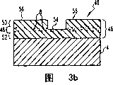
Fig. 3 a, 3b are the profiles of a kind of modification of the described galley of 2a, 2b;
Fig. 4 a, 4b are the profiles of a kind of modification of the described galley of 2a, 2b;
Fig. 5 a, 5b, 5c are the profiles of the 3rd embodiment of galley constructed in accordance;
Fig. 6 a, 6b, 6c are the profiles of the 4th embodiment of galley;
Fig. 7 a, 7b, 7c and 7d are the profiles of the 5th embodiment of galley constructed in accordance;
Fig. 8 a, 8b, 8c are the profiles of the 6th embodiment of galley constructed in accordance;
Fig. 9 a, 9b and 9c are the profiles of 8a, 8b and a kind of modification of the described galley of 8c.
The detailed description of preferred implementation
Below for convenience, directed consistent in the term that uses among the present invention " top ", " following ", " the right ", " left side ", " vertically ", " level ", " top ", " bottom " and the term that derives from thereof and the accompanying drawing.But, understand that except other has explanation, the present invention can have different modification and sequence of steps.Also to understand, accompanying drawing and describe below shown in and described specific device and method only be exemplary embodiment of the present invention.Therefore, specific dimensions and other physical features in the embodiment that discloses herein can not be considered to limit the present invention.
The most basic form of the present invention comprises the galley that is used for imaging, one or more layers hydrophilic acrylic polymer layer that it has individual base material and position laser thereon to ablate.Term " laser can be ablated " refers to that material or layer absorb and causes that it ablates and the infrared laser of any material ablation above the ablated material.Base material relates to or does not relate to printing, depends on whether top polymeric layer ablates fully.
For each embodiment described below, base material can be a metal, preferred aluminium alloy or steel, paper or plastics.Suitable aluminium alloy comprises the alloy of AA1000,3000 and 5000 series.Suitable steel substrate has low-carbon (LC) steel disc and stainless steel substrates.
Aluminum alloy base material preferably has about 1-30 mil, preferably about 5-20 mil, the thickness of 8-20 mil more preferably from about.Especially preferred be thickness be about 8.8 mils without anodized aluminum alloy base material.
Base material can be rolling, maybe can also carry out ornamenting by roll-in veining, chemical veining or electrochemistry veining or their compound mode.The roll-in veining can be undertaken by the combination of electron discharge veining (EDT), laser-graining, electron beam veining, mechanical line physics and chemistry, chemical veining, electrochemistry veining or these methods.Preferred mechanical veining technology comprises peening and brush decorations granulating.Formed grain surface provides a kind of more has the surface of diffusive than the surface of rolling mistake, and higher surface uniformity is arranged simultaneously.During laser ablation, the uneven surfaces defective is relevant with laser light back reflection.The grain surface of goods of the present invention can make the laser light back reflection minimum, and improves the uniformity and the efficient of laser ablation process.
The first type surface of metal surface is cleaned, and removes surface contaminant, for example the lubricant residue.Some suitable chemical surface cleaning agents comprise alkali and aqueous acid, also can the using plasma radiation, corona discharge and laser emission.
In first embodiment of the galley of the present invention 2 shown in Fig. 1 a, the 1b, base material 4 is covered by can ablate parts 6 of laser.Can ablate parts 6 of laser are formed by acrylic polymer, wherein are dispersed with many particles 8 to laser-sensitive (absorption radiation).
For this first embodiment and as described below, this acrylic polymer is hydrophilic.Preferred acrylic polymer is the copolymer with organic phosphorus compound.Term used herein " organic phosphorus compound " comprises organic phosphoric acid, organic phospho acid, organic phosphinic acids and various salt thereof, ester, inclined to one side salt and partial ester.Organic phosphorus compound can with acrylic or methacrylic acid copolymerization.The copolymer of preferred vinyl phosphonic acids especially contains about 5-50 mole % vinyl phosphonate and the acrylic acid copolymer of about 50-95 mole %, and the molecular weight of this copolymer is about 20000-100000.Especially preferably the copolymer that contains have an appointment 70 moles of % acrylic acid and about 30 moles of % vinyl phosphonates.Described acrylic polymer can batch apply or apply rolling up continuously sheet with conventional coating process, and described coating process comprises roller coat, powder coated, spraying, vacuum coated, emulsion coating or dip-coating.Acrylic polymer preferably applies in the mode of roller coat, and the thickness of general coating is about the 0.01-1.0 mil, preferably is about the 0.1-0.3 mil.Comprise that vinyl phosphonate and acrylic acid acrylic polymer are hydrophilic.
Laser-sensitive particle 8 is formed by any kind material that absorbs infrared radiation.Preferred particle is that dyestuff or average grain diameter are about 7 microns or littler inorganic particle.Preferred dyestuff is the dyestuff of azines or azide or the about 500-1100nm wave-length coverage light of any other absorption.Especially preferred dyestuff is Nigrosine Base BA, available from the Bayer AG of Pennsylvania Pittsburgh.Can ablate parts 6 when comprising AA-E base phosphonic acid copolymer and azine dye when laser, and the preferred concentration of dyestuff is about 1-10 weight %, preferably is about 3-5 weight %.Inorganic particle can be metal, mineral matter or carbon granule.Metallic particles can be magnesium, copper, cobalt, nickel, lead, cadmium, titanium, iron, bismuth, tungsten, tantalum, silicon, chromium, aluminium or zinc, preferred iron, aluminium, nickel or zinc.Can ablate parts 6 when comprising AA-E base phosphonic acid copolymer and manganese oxide when laser, and the preferred concentration that average grain diameter is about 0.6 micron manganese oxide particle is about 1-15 weight %.Mineral particle can be oxide, boride, carbide, sulfide, halide or the nitride of above-mentioned metal, perhaps clay.Clay comprises alumina silicate and hydrosilicate for example feldspar and kaolinite (kaolinate).Carbon can use with carbon black, graphite, form dim or other commercially available carbonaceous particles.Have the different mixtures of forming particles also within the scope of the invention.Though acrylic polymer has inherent hydrophily,, comprise capacity laser-sensitive particle has the laser-sensitive particle with regard to the composition that makes acrylic polymer lipophile.The present invention adopts the polymer composition with acrylic polymer and capacity laser-sensitive particle, makes polymer composition have lipophile.
In use, galley 2 is used laser imaging, described laser galley to accept printing ink with the zone of exposing base material in to laser parts 6 ablations of can ablating, shown in Fig. 1 b.The zone 10 of base material is exposed in the ablation of parts 6, stays not ablated area 12.Zone 10 has different compatibilities with 12 pairs of printed liquid.Aluminium is preferred substrates, because aluminium plays hydrophily or oil loving effect according to can the ablate hydrophily and the oleophylic China ink of parts 6 of laser on it.At the laser parts of can ablating is under the oil loving situation, and aluminium base just plays the hydrophily effect.The printed liquid printing ink that contains water or hydrojet (fountain solution) can adhere on 12 (parts 6 of not ablating) of zone, and zone 10 (aluminium bases 4) are then covered by water or hydrojet.
Also can be shown in Fig. 1 c and 1d, plate 2 ' comprises base material 4 and by the laser that the polymer composition that contains acrylic polymer and many laser-sensitive particles 8 the forms parts 6 ' of can ablating.Laser can be ablated the top 14 of parts 6 ' through handling and having a lipophile.The preferred processing comprises corona discharge, electron beam discharge, laser irradiation or heating.Shown in Fig. 1 d, plate 2 ' is preferably used laser imaging, removes its top 14 fully, exposes hydrophilic region 16, stays the lipophile zone 18 of not ablating.The laser parts 6 ' of can ablating also can be formed by lipophile polymer and many laser-sensitive particles 8.Suitable lipophile polymer comprises thermoplasticity or elastomeric polymer.Preferred thermoplastic comprises for example PETG (PET) of polyvinyl chloride, polyolefin, Merlon, polyamide and polyester.Suitable elastomeric polymer comprises polybutadiene, polyether urethane and (butadiene-acrylonitrile) copolymer.Thermoplasticity or elastomeric polymer can be applied on the base material 4 by United States Patent (USP) № 5711911,5795647 and 5988066 described methods, and the content of these patents is all with reference to being incorporated into this.The top 14 usefulness said methods of lipophile polymer are handled and are made its possess hydrophilic property.When the lipophile polymer was used for laser and can ablates parts 6 ', the zone 16 of exposing was exactly oil loving, and the zone 18 of Shao Shiing is not exactly hydrophilic.
In second embodiment of the present invention, the laser parts of can ablating only contain the laser-sensitive particle in its part.Shown in Fig. 2 a and 2b, plate 20 comprises that laser that the acrylic polymer that wherein is dispersed with the laser-sensitive particle the is formed parts 26 of can ablating cover.Layer 28 is positioned near can ablate or the close position of parts 26 bottoms of laser, and the top 30 that is not contained the parts 26 of laser-sensitive particle covers.Shown in Fig. 2 b, plate 20 is preferably used laser imaging, removes part 30 fully, and part ablation layer 28, exposes zone 32, stays not ablated area 34.Ablated zone 32 is oil loving, and the zone 34 of Shao Shiing not is hydrophilic.The printed liquid printing ink that contains water or hydrojet can adhere on the zone 32, and zone 34 is covered by water or hydrojet.
Also can be shown in Fig. 3 a and 3b, the laser that plate 40 comprises base material 4 and has an acrylic polymer layer 48 parts 46 of can ablating, described layer 48 contains the laser-sensitive particle in the zone between top 50 and bottom 52.Do not contain laser-sensitive particle 8 in top 50 and the bottom 52.In the bottom 52 insulated particle (not shown), for example barium sulfate particle can be arranged.Other suitable insulation particles comprise titanium dioxide, aluminium oxide or silica or their composition.The concentration of insulated particle in bottom 52 preferably up to about 60 weight %, is more preferably 50 weight %.It is believed that the heat that insulated particle can stop the laser-sensitive particle 8 crossed by radiation treatment to be produced passes on the metal base 4.
Shown in Fig. 3 b, plate 40 is preferably used laser imaging, removes top 50 fully, and part ablation layer 48, and lipophile zone 54 is exposed in the bottom 52 of not ablating, and stays the hydrophilic region 56 of not ablating.
In addition, as shown in Figs. 4a and 4b, the present invention includes plate 60, the laser that it has base material 4 and has an acrylic polymer layer 68 parts 66 of can ablating, layer 68 is contiguous or contain laser-sensitive particle 8 near can the ablate position at top of parts 66 of laser.The bottom 70 that does not contain the parts 66 of laser-sensitive particle is positioned at below the layer 68.For example barium sulfate particle of insulated particle (not shown) can be arranged, as described in the bottom 70 to plate 40.Shown in Fig. 4 b, plate 60 preferably use laser imaging, and complete ablation layer 68 exposes the zone 72 of bottom 70, stays not ablated area 74.Zone 74 is oil loving, and zone 72 is hydrophilic.
In each plate 20,40 and 60, layer 28,48 and 68 determining positions can the ablate laser ablation degree of depth of parts 26,46 and 66 of each laser.In plate 20,40 and 60, each layer 28,48 and 68 is oil loving, and each top 30 and 50 and bottom 70 be hydrophilic.Be preferably formed situation shown in Fig. 2 b, 3b and 4b by the laser ablation imaging, make that the printing ink in the printed liquid can adhere to the layer 28,48 and 68 that respectively exposes, and water or hydrojet can adhere on the not ablated area of each several part 30,50 and 70.
The formation method of plate 20 can be like this, and the acrylic polymer that at first will contain laser-sensitive particle 8 is applied on the base material 4, forms layer 28, and the acrylic polymer that will not contain the laser-sensitive particle then is applied on the layer 28, forms top 30.Plate 60 forms in the same way, and different is that the layer 70 that does not contain the laser-sensitive particle applied before containing the layer 68 of laser-sensitive particle.Plate 40 can form equally like this, the acrylic polymer that at first will not contain the laser-sensitive particle is applied on the base material 4, make bottom 52, the acrylic polymer that will contain laser-sensitive particle 8 then is applied on the bottom 52, form layer 48, and the acrylic polymer that will not contain the laser-sensitive particle is applied on the layer 48 formation top 50.Apply the appropriate method that contains or do not contain the acrylic polymer of laser-sensitive particle and comprise roller coat, spraying, dip-coating, emulsion coating, powder coated and vacuum coated.
The 3rd embodiment of the present invention is shown in Fig. 5 a, 5b and 5c, and it is galley 80, and this plate has base material 4 and by the laser that acrylic polymer forms can ablate parts 86 and intermediate layer 88.Laser-sensitive particle 8 is scattered in laser can ablate in the layer 90 of parts 86, and layer 90 is positioned at laser can the ablate vicinity or near the position of parts 86 bottoms, and parts 86 are covered by the top 92 that it does not contain the laser-sensitive particle.Intermediate layer 88 can be formed by above-mentioned thermoplasticity or elastomeric polymer.Have been found that the laser-sensitive particle is present in the laser laser at parts and the substrate interface place parts of can ablating of can ablating, in the intermediate layer between them the time, the cohesive of base material is had raising.Intermediate layer 88 is used for improving can the ablate cohesive of parts 86 and base material 4 of laser.In the layer 88 the insulated particle (not shown) can be arranged, for example barium sulfate particle is as above described in the face of plate 40.
Shown in Fig. 5 b, plate 80 is preferably used laser imaging, removes part 92 fully, and part ablation layer 90, exposes zone 94, stays not ablated area 96.Zone 94 is oil loving, and zone 96 is hydrophilic.The laser parts 86 of can ablating also can all remove by complete ablation layer 90, shown in Fig. 5 c, expose the zone 98 in lipophile intermediate layer 88, stay not ablated area 96.Under any situation, the printing ink of printed liquid all can adhere to and expose on zone 94 (Fig. 5 b) or 98 (Fig. 5 c), and water or hydrojet then adhere to not on the ablated area 96.
Fig. 6 a, 6b and 6c show the 4th embodiment of the present invention, and it comprises galley 100, and this plate has base material 4, the laser parts 106 of can ablating, and maybe can also have individual intermediate layer 108.Intermediate layer 108 is identical with the layer 88 of plate 80, can be formed by above-mentioned thermoplasticity or elastomeric polymer, wherein the insulated particle (not shown) can be arranged, and for example barium sulfate particle is as above described in the face of plate 40.Laser can ablate parts 106 comprise the ground floor 110 of the acrylic polymer that wherein is dispersed with laser-sensitive particle 8 with to the compatibility of printed liquid and the second layer 112 of one or more layers different polymer of 108 and 110.The polymer that is suitable for the second layer 112 is siloxane polymer or copolymer (below be referred to as siloxane polymer), and they generally are hydrophobicity and oil repellency.Suitable siloxane polymer comprises fluorosilicone, dimethyl siloxane, diphenyl siloxane and nitryl siloxanes.
Shown in Fig. 6 b, plate 100 is preferably used laser imaging, all removes the second layer 112, and part ablation layer 110, exposes zone 114, stays not ablated area 116.Zone 116 be hydrophobicity with oil repellency, the zone 114 is oil loving.The laser parts 106 of can ablating also can all remove by complete ablation layer 110, shown in Fig. 6 c, expose the zone 118 in lipophile intermediate layer 108, stay not ablated area 116.Plate 100 can use anhydrous printed liquid, and the printed liquid ink adhesion is on the lipophile zone 114 of exposing (Fig. 6 b) or 118 (Fig. 6 c), by not ablated area 116 repulsions.
The 5th embodiment of the present invention shown in Fig. 7 a and 7b is galley 120, and it has base material 4 and the laser parts 126 of can ablating, and base material 4 maybe can have layer preprocessing part 122.The preprocessing part 122 of base material 4 can be a polymeric layer independently, maybe can be whole conversion coating.Suitable polymers is acrylic polymer, hydrophily polypropylene component and thermoplasticity or elastomeric polymer, and they can be by roller coat, spraying, dip-coating, emulsion coating, powder coating or vacuum coated to base material 4.Though polypropylene has inherent lipophile, the composition that contains the capacity filler particles is hydrophilic.The appropriate filler particle comprises above-mentioned laser-sensitive particle.Another kind is applicable to that the polymer of preprocessing part 122 is electropaining polymer, epoxy resin for example, be called as described in the United States Patent (USP) № 09/519018 that " Electrocoating Process formaking Lithographic Sheet Material " transfer assignee of the present invention as the name of submitting on March 3rd, 2000, its content is with reference to being incorporated into this.When preprocessing part 122 is independently during polymeric layer, in this part 122 the insulated particle (not shown) can be arranged, for example barium sulfate particle is as above described in the face of plate 40.When base material 4 was aluminium or another kind of metal, preprocessing part 122 can be conversion coating (reaction surface of base material 4), rather than was applied to the extra play on the base material 4.The preferred conversion coating that is used for preprocessing part 122 comprises salt or the compound of Zn, Cr, P, Zr, Ti or Mo.
Laser can ablate parts 126 comprise by inside be dispersed with ground floor 128 that the acrylic polymer of laser-sensitive particle 8 forms with by the polymer formed second layer 130 different to the compatibility of printed liquid and layer 128.The material that is suitable for the second layer 130 is a hydrophilic polymer, for example acrylic polymer and hydrophily polypropylene component.The polymer of the second layer 130 also can be hydrophobicity and oil repellency polymer, for example siloxane polymer or copolymer.Suitable silicone composition comprises fluorosilicone, dimethyl siloxane, diphenyl siloxane and nitryl siloxanes.
Shown in Fig. 7 b, galley 120 is preferably used laser imaging, all removes the second layer 130, and part ablation layer 128, exposes lipophile zone 132, stays not ablated area 134.When the second layer 130 was formed by acrylic polymer, zone 134 was hydrophilic.Printed liquid printing ink can adhere to the zone 132 of exposing, and water or hydrojet can adhere to not ablated area 134.When the second layer 130 was formed by siloxane polymer, zone 134 was hydrophobicity and oil repellency, and this plate 120 can use anhydrous printed liquid.The second layer 130 that the printing ink of printed liquid is contained siloxanes repels, and adheres on the lipophile zone 132.
Also can be, shown in Fig. 7 c and 7d, plate 120 ' comprises base material 4 and the laser parts 126 ' of can ablating, and these parts and the laser of plate 120 parts 126 of can ablating are similar, and different is that the second layer 130 ' is formed by for example above-mentioned thermoplasticity of lipophile polymer or elastomeric polymer.Handle on the top 136 of the second layer 130 ', and possess hydrophilic property is as above described in the face of plate 2 '.Try Fig. 7 d, plate 120 ' is preferably used laser imaging, removes the second layer 130 ' fully, exposes the lipophile polymer of layer 128, and stays not ablated area 134 '.The second layer 130 ' can also contain many laser-sensitive particles.The lipophile polymer of the second layer 130 ' is exposed on the hydrophily top 136 of also can ablating.
Aspect, pass of the present invention is to use, and comprises the laser of the polymer composition that contains acrylic polymer or other hydrophilic polymers and the many laser-sensitive particles parts of can ablating to small part.Find that adding has the galley of this polymer composition can successfully pass through the laser ablation imaging, and enough durable in being applied to repeatedly print cycle.But contain the laser-sensitive particle in the ablative polymer layer though the present invention is described as be in, this does not mean that limitation of the present invention.The laser emission desired polymeric layer of ablating can be controlled, wherein the laser-sensitive particle can be do not contained.
The present invention also comprises such galley, and it has the printing unit that will not ablate or only be given the part ablation by image-forming radiation and formation method.Fig. 8 a and 8b show galley 140, and it has base material 4 and polymeric printing parts 146.The polymer of printing unit 146 has initial compatibility to printed liquid, is preferably formed by acrylic polymer, and it is hydrophilic so just making the upper surface 148 of printing unit 146.In this embodiment, there is not the laser-sensitive particle in the printing unit 146.Shown in Fig. 8 a, when image-forming radiation that is exposed to laser etc., the part 150 of upper surface becomes lipophile, and unexposed part 152 still keeps hydrophily (Fig. 8 b), has just formed printable image thus.Can think that emittance changes the surface chemical property of upper surface 148, make the compatibility of 148 pairs of printed liquid of upper surface change.Also can be shown in Fig. 8 c, can ablate with radiant section and go part 150 ', also cause to be positioned at below the surface 148 and the part of exposing during ablating 150 ' changes the compatibility of printing ink.For example, when printing unit 146 is initial when being hydrophily and oil repellency, the part of exposing 150 ' can become lipophile after radiation treatment stronger, and the part of not exposing 154 still keeps hydrophily and oil repellency.
The galley 160 that comprises laser-sensitive particle 8 is shown in Fig. 9 a and 9b.Galley 160 has base material 4 and polymeric printing parts 166.The polymer of printing unit 166 has initial compatibility to printed liquid, is preferably formed by acrylic polymer, makes that the upper surface 168 of printing unit 166 is hydrophilic.Printing unit 166 comprises ground floor 170, and it is formed by acrylic polymer, and contains the laser-sensitive particle 8 that is scattered in wherein, and is similar to the plate 40 shown in Fig. 3 a.When being exposed to the image-forming radiation of laser etc., shown in Fig. 9 a, the part 172 of upper surface 168 just becomes lipophile, and unexposed part 174 still keeps hydrophily (Fig. 9 b), forms thus and can print image.Can think that radiation is absorbed by particle 8, make particle 8 vibrations, produce heat, be transmitted on the upper surface 168.The surface chemical property that can change upper surface 168 is thought in the heating of upper surface 168, its compatibility to printed liquid is changed.In addition, shown in Fig. 9 c, radiation also can part ablating part 172 ', causes that also part 172 ' changes the compatibility of printing ink.For example, when printing unit 166 initially was hydrophily and oil repellency, part 172 ' just can become more oleophylic after radiation treatment, and the part of not exposing 174 still keeps hydrophily and oil repellency.
It (for example initially is oil loving that other polymer compositions also can be used for printing unit 146 and 166, and after being exposed to image-forming radiation, become hydrophilic polymers), so long as the initial and final compatibility of upper surface 148 or 168 pairs of printed liquid is different, make it possible to carry out lithographic printing.Plate 140 and 160 can be as method manufacturing as described in above-mentioned plate 2,20,40 and 60.
Technical staff in the industry can be not difficult to understand, describes described content above not breaking away from, and can change the present invention.Such change should be to be contained in the scope of claims, unless claim has explanation in addition.Therefore, the specific embodiment of Xiang Ximiaoshuing only is illustrative herein, does not limit the scope of the invention, and scope of the present invention is limited by claims and any and whole equivalents thereof.
Claims (70)
1. galley, it comprises:
Have a first type surface substrate and
The laser parts of can ablating, these parts comprise the polymer composition that is positioned on the described first type surface, the described laser parts of can ablating comprise such polymer composition, said composition comprises acrylic polymer and many laser-sensitive particles, and described polymer composition can be ablated when the described laser-sensitive particle of laser irradiation.
2. galley as claimed in claim 1 is characterized in that described substrate comprises metal, paper or plastics.
3. galley as claimed in claim 2 is characterized in that described base material comprises aluminium.
4. galley as claimed in claim 3 is characterized in that described first type surface modified by at least a veining in roll-in veining, mechanical line physics and chemistry, chemical veining or the electrochemistry veining.
5. galley as claimed in claim 1 is characterized in that described acrylic polymer comprises organic phosphorus compound.
6. galley as claimed in claim 5 is characterized in that described acrylic polymer comprises the copolymer of acrylic acid and vinyl phosphonate.
7. galley as claimed in claim 1 is characterized in that described laser-sensitive particle is selected from dyestuff, metal, mineral matter and carbon.
8. galley as claimed in claim 1, it is characterized in that can the ablate part of parts of described laser comprises that one deck does not contain the layer of laser-sensitive particle, the described layer that does not contain the laser-sensitive particle is different to can the ablate remainder of parts of the compatibility of printed liquid and the laser that contains the laser-sensitive particle.
9. galley as claimed in claim 8, it is characterized in that described layer be positioned at described laser can ablate parts described remainder below.
10. galley as claimed in claim 8 is characterized in that described layer is positioned at can the ablate centre of described remainder of parts of described laser.
11. galley as claimed in claim 8, it is characterized in that described layer be positioned at described laser can ablate parts described remainder above.
12. galley as claimed in claim 1 is characterized in that can the ablate part of parts of described laser comprises second polymer composition, said composition is different with described polymer composition to the compatibility of printed liquid.
13. galley as claimed in claim 12 is characterized in that described second polymer composition comprises hydrophilic acrylic polymer, hydrophily polypropylene component, thermoplasticity or elastomeric polymer or siloxane polymer.
14. galley as claimed in claim 13 is characterized in that described second polymer composition comprises thermoplasticity or elastomeric polymer, the upper surface of the described second layer is hydrophilic.
15. a galley, it comprises:
Substrate;
Be positioned at the ground floor above the described substrate, this layer comprises first polymer composition, and described first polymer composition comprises acrylic polymer and many laser-sensitive particles; With
Be positioned at the second layer above the described ground floor, this layer comprises second polymer composition;
Described first polymer composition is different to the compatibility of printed liquid with second polymer composition, and described first polymer composition can be ablated when the described laser-sensitive particle of laser irradiation.
16. galley as claimed in claim 15 is characterized in that described acrylic polymer comprises the copolymer of acrylic acid and vinyl phosphonate.
17. galley as claimed in claim 15 is characterized in that described substrate comprises aluminium.
18. galley as claimed in claim 17 is characterized in that described first type surface modified by at least a veining in roll-in veining, mechanical line physics and chemistry, chemical veining or the electrochemistry veining.
19. galley as claimed in claim 15 is characterized in that described second polymer composition comprises acrylic polymer, hydrophily polypropylene component, thermoplasticity or elastomeric polymer or siloxane polymer.
20. galley as claimed in claim 19, it also is included in below the described ground floor the 3rd layer.
21. galley as claimed in claim 20 is characterized in that described the 3rd layer comprises the component that is selected from acrylic polymer, hydrophily polypropylene component and thermoplasticity or elastomeric polymer.
22. galley as claimed in claim 21 is characterized in that described second polymer composition comprises acrylic polymer or siloxane polymer, described the 3rd layer comprises thermoplasticity or elastomeric polymer.
23. galley as claimed in claim 21 is characterized in that described the 3rd layer is applied on the described substrate by roller coat, spraying, dip-coating, emulsion coating or vacuum coated.
24. galley as claimed in claim 20 is characterized in that described the 3rd layer comprises salt or the conversion of compounds coating that contains Zn, Cr, P, Zr, Ti or Mo.
25. galley as claimed in claim 20 is characterized in that described the 3rd layer comprises that electropaining arrives described on-chip epoxy resin.
26. a galley, it comprises:
Have first type surface substrate and
Laser with upper and lower parts of can ablating, the described laser parts of can ablating comprise the polymer composition that is positioned on the described first type surface, the polymer composition on described top is processed into the polymer composition that makes described top the compatibility of printed liquid is changed over second compatibility from first compatibility, described thus top is different with described bottom to the compatibility of printed liquid, make when the described top of laser irradiation, described top just removes, thereby exposes described bottom;
Described polymer composition comprises acrylic polymer and many laser-sensitive particles, and described polymer composition can be ablated when the described laser-sensitive particle of laser irradiation.
27. galley as claimed in claim 26 is characterized in that described top handles by corona discharge, electron beam discharge, laser emission or heating.
28. galley as claimed in claim 26 is characterized in that described polymer composition comprises polymer and many laser-sensitive particles.
29. the galley of an available laser emission imaging, it comprises:
Substrate with first type surface; With
Be positioned on the described first type surface of substrate and have the printing unit of upper surface, described upper surface comprises polymer composition, described upper surface can not ablated by image-forming radiation, described upper surface has initial compatibility to printed liquid, after described printing unit was subjected to the image-forming radiation irradiation, it becomes had different compatibilities to printed liquid;
Described polymer composition comprises acrylic polymer and many laser-sensitive particles, and described polymer composition can be ablated when the described laser-sensitive particle of laser irradiation.
30. galley as claimed in claim 29 is characterized in that described polymer composition comprises acrylic polymer.
31. galley as claimed in claim 30 is characterized in that described polymer composition comprises organic phosphorus compound.
32. galley as claimed in claim 31 is characterized in that described acrylic polymer comprises the copolymer of acrylic acid and vinyl phosphonate.
33. galley as claimed in claim 29 is characterized in that described printing unit comprises the ground floor that is positioned at below the described upper surface, described ground floor comprises polymer and many radiation-absorbing particles.
34. galley as claimed in claim 33 is characterized in that described radiation-absorbing particles is selected from dyestuff, metal, mineral matter and carbon.
35. galley as claimed in claim 33 is characterized in that described ground floor comprises acrylic polymer.
36. galley as claimed in claim 33, it also comprises the second layer that is positioned at below the described ground floor.
37. galley as claimed in claim 36 is characterized in that the described second layer comprises acrylic polymer.
38. galley as claimed in claim 36 is characterized in that the described second layer comprises salt or the conversion of compounds coating that contains Zn, Cr, P, Zr, Ti or Mo.
39. the formation method of a lithographic plate, it may further comprise the steps:
(a) provide a kind of printing unit that upper surface comprises polymer composition that has, described upper surface can not ablated by image-forming radiation, described upper surface has initial compatibility to printed liquid, after described printing unit was subjected to the image-forming radiation irradiation, it becomes had different compatibilities to printed liquid; Described polymer composition comprises acrylic polymer and many laser-sensitive particles, and described polymer composition can be ablated when the described laser-sensitive particle of laser irradiation;
(b) with a part of upper surface of the imaging irradiation irradiation printing unit that has the pattern corresponding with a kind of image, and do not cause that parts ablate, what make upper surface is subjected to that according to part the compatibility of printed liquid and upper surface not to be subjected to shine part different.
40. method as claimed in claim 39 is characterized in that described polymer composition comprises acrylic polymer.
41. method as claimed in claim 39 is characterized in that described printing unit comprises the ground floor that is positioned at below the upper surface, described ground floor comprises polymer and many radiation-absorbing particles.
42. method as claimed in claim 41 is characterized in that described radiation-absorbing particles is selected from dyestuff, metal, mineral matter and carbon.
43. galley as claimed in claim 42 is characterized in that described ground floor comprises acrylic polymer.
44. the galley of an available laser emission imaging, it comprises:
Substrate with first type surface;
Be positioned on the described substrate first type surface and have the printing unit of upper surface, described upper surface comprises polymer composition, described upper surface can be ablated by image-forming radiation and the bottom of exposing described printing unit, described bottom has the initial compatibility to printed liquid, after described printing unit was subjected to the image-forming radiation irradiation, it becomes had different compatibilities to printed liquid;
Described polymer composition comprises acrylic polymer and many laser-sensitive particles, and described polymer composition can be ablated when the described laser-sensitive particle of laser irradiation.
45. galley as claimed in claim 44 is characterized in that described polymer composition comprises acrylic polymer.
46. galley as claimed in claim 45 is characterized in that described polymer composition comprises organic phosphorus compound.
47. galley as claimed in claim 46 is characterized in that described organic phosphorus compound comprises the copolymer of acrylic acid and vinyl phosphonate.
48. galley as claimed in claim 44 is characterized in that described printing unit comprises the ground floor that is positioned at below the described upper surface, described ground floor comprises polymer and many radiation-absorbing particles.
49. galley as claimed in claim 48 is characterized in that described radiation-absorbing particles is selected from dyestuff, metal, mineral matter and carbon.
50. galley as claimed in claim 48, it also comprises the second layer that is positioned at below the described ground floor.
51. galley as claimed in claim 50 is characterized in that the described second layer comprises acrylic polymer.
52. the formation method of a lithographic plate, it may further comprise the steps:
(a) provide a kind of printing unit that upper surface comprises polymer composition that has, the upper surface of described printing unit can be ablated by image-forming radiation, described polymer composition has initial compatibility to printed liquid, after being subjected to the image-forming radiation irradiation, it becomes has different compatibilities to printed liquid; Described polymer composition comprises acrylic polymer and many laser-sensitive particles, and described polymer composition can be ablated when the described laser-sensitive particle of laser irradiation;
(b) upper surface with printing unit is exposed in the pattern of the image-forming radiation corresponding with a kind of image, and the parts of ablating thus expose following part, and makes the lower part that exposes become the compatibility different to printed liquid to the initial compatibility of printed liquid.
53. method as claimed in claim 52 is characterized in that described polymer composition comprises acrylic polymer.
54. galley as claimed in claim 52 is characterized in that described printing unit comprises the ground floor that is positioned at below the described upper surface, described ground floor comprises polymer and many radiation-absorbing particles.
55. galley as claimed in claim 54 is characterized in that described radiation-absorbing particles is selected from dyestuff, metal, mineral matter and carbon.
56. galley as claimed in claim 54 is characterized in that described ground floor comprises acrylic polymer.
57. a galley, it comprises:
Substrate with first type surface;
The insulating barrier that contains polymer composition and many insulating elements; With
Contain polymer composition, be positioned at the printing unit on the described insulating barrier;
Described polymer composition comprises acrylic polymer and many laser-sensitive particles, and described polymer composition can be ablated when the described laser-sensitive particle of laser irradiation.
58. galley as claimed in claim 57 is characterized in that described insulating element base material comprises barium sulfate, titanium dioxide, aluminium oxide or silica granules or their composition.
59. galley as claimed in claim 57 is characterized in that described polymer composition contains organic phosphorus compound.
60. galley as claimed in claim 59 is characterized in that described polymer composition comprises the copolymer of acrylic acid and vinyl phosphonate.
61. galley as claimed in claim 57 is characterized in that also comprising radiation-absorbing particles in the described printing unit that described particle is selected from dyestuff, metal, mineral matter and carbon.
62. galley as claimed in claim 57 is characterized in that described printing unit is that laser can be ablated.
63. galley as claimed in claim 57 is characterized in that described printing unit has initial compatibility to printed liquid, and after printing unit is subjected to image-forming radiation irradiation, can become printed liquid is had different compatibilities.
64. a galley, it comprises:
Substrate with first type surface;
Contain polymer composition and be positioned at laser on the described substrate first type surface parts of can ablating, the described laser parts of can ablating comprise the polymer composition that contains acrylic polymer, said composition comprises organic phosphorus compound and many laser-sensitive particles, and described polymer composition can be ablated when laser shines described laser-sensitive particle.
65., it is characterized in that described acrylic polymer comprises the copolymer of acrylic acid and vinyl phosphonate as the described galley of claim 64.
66. as the described galley of claim 64, it is characterized in that can the ablate part of parts of described laser comprises that one deck does not contain the layer of laser-sensitive particle, can ablate that to contain the remainder of laser-sensitive particle different for parts described not containing to the compatibility of printed liquid and laser to the layer of laser-sensitive particle.
67. as the described galley of claim 65, it also comprises:
The second layer that contains second polymer composition, described second polymer composition be positioned at described laser can ablate parts above;
Can the ablate polymer composition of parts of described laser is different to the compatibility of printed liquid with second polymer composition.
68. as the described galley of claim 67, it is characterized in that described second polymer composition contains acrylic polymer or siloxane polymer, described galley also comprises the 3rd layer, described the 3rd layer comprises thermoplasticity or elastomeric polymer.
69. as the described galley of claim 64, it is characterized in that the described laser parts of can ablating have the upper and lower, can handle the polymer composition on described top so that the polymer composition on described top is changed over second compatibility to the compatibility of printed liquid from first compatibility, described thus top is different with described bottom to the compatibility of printed liquid, make when the described top of laser irradiation, described top removes, thereby exposes described bottom.
70. the formation method of a lithographic plate, it may further comprise the steps:
(a) provide a kind of printing unit that upper surface comprises polymer composition that has, described polymer composition comprises acrylic polymer and many laser-sensitive particles, described polymer composition can be ablated when the described laser-sensitive particle of laser irradiation, described acrylic polymer contains organic phosphorus compound, the upper surface of described printing unit can be ablated by image-forming radiation, described polymer composition has initial compatibility to printed liquid, and after being subjected to image-forming radiation irradiation, becoming printed liquid is had different compatibilities;
(b) upper surface with printing unit is exposed in the patterned image-forming radiation corresponding with a kind of image, thus parts are ablated, expose following part, and make the lower part that exposes become different compatibility printed liquid to the initial compatibility of printed liquid.
Applications Claiming Priority (6)
| Application Number | Priority Date | Filing Date | Title |
|---|---|---|---|
| US09/662,400 | 2000-09-14 | ||
| US09/662,400 US6521391B1 (en) | 2000-09-14 | 2000-09-14 | Printing plate |
| US09/680,363 US6569601B1 (en) | 2000-09-14 | 2000-10-05 | Radiation treatable printing plate |
| US09/680,363 | 2000-10-05 | ||
| US09/905,782 US6673519B2 (en) | 2000-09-14 | 2001-07-14 | Printing plate having printing layer with changeable affinity for printing fluid |
| US09/905,782 | 2001-07-14 |
Publications (2)
| Publication Number | Publication Date |
|---|---|
| CN1555314A CN1555314A (en) | 2004-12-15 |
| CN1309560C true CN1309560C (en) | 2007-04-11 |
Family
ID=27418065
Family Applications (1)
| Application Number | Title | Priority Date | Filing Date |
|---|---|---|---|
| CNB018156266A Expired - Fee Related CN1309560C (en) | 2000-09-14 | 2001-09-13 | Printing plate |
Country Status (8)
| Country | Link |
|---|---|
| US (1) | US6673519B2 (en) |
| EP (1) | EP1317337B1 (en) |
| JP (1) | JP2004508971A (en) |
| CN (1) | CN1309560C (en) |
| AT (1) | ATE309907T1 (en) |
| DE (1) | DE60115067T2 (en) |
| ES (1) | ES2251511T3 (en) |
| WO (1) | WO2002022360A2 (en) |
Families Citing this family (13)
| Publication number | Priority date | Publication date | Assignee | Title |
|---|---|---|---|---|
| US6521391B1 (en) * | 2000-09-14 | 2003-02-18 | Alcoa Inc. | Printing plate |
| DE10061114A1 (en) * | 2000-12-07 | 2002-06-13 | Basf Drucksysteme Gmbh | Photosensitive flexographic printing element with IR-ablative layer comprising polyether polyurethane |
| MXPA06006738A (en) | 2003-12-19 | 2006-08-31 | Univ North Carolina | Methods for fabricating isolated micro- and nano- structures using soft or imprint lithography. |
| US8187794B2 (en) * | 2007-04-23 | 2012-05-29 | Eastman Kodak Company | Ablatable elements for making flexographic printing plates |
| US8349462B2 (en) | 2009-01-16 | 2013-01-08 | Alcoa Inc. | Aluminum alloys, aluminum alloy products and methods for making the same |
| US8114572B2 (en) * | 2009-10-20 | 2012-02-14 | Eastman Kodak Company | Laser-ablatable elements and methods of use |
| JP6221320B2 (en) * | 2013-04-16 | 2017-11-01 | 大日本印刷株式会社 | Method for producing functional element and functional element |
| CN107850838A (en) * | 2015-06-17 | 2018-03-27 | 爱克发有限公司 | Flexographic printing original plate and its magnetic developer |
| CN106835857A (en) * | 2015-12-04 | 2017-06-13 | 陈宣达 | A kind of cardboard with false-proof texture and the ink plate for the cardboard printing |
| WO2018165053A1 (en) | 2017-03-06 | 2018-09-13 | Arconic Inc. | Methods of preparing 7xxx aluminum alloys for adhesive bonding, and products relating to the same |
| CN111771162B (en) * | 2018-02-16 | 2024-05-14 | 米瑞控公司 | Reticle element and relief image forming system |
| CN114506164A (en) * | 2021-12-27 | 2022-05-17 | 北京中钞钞券设计制版有限公司 | Plate material, printing plate, preparation method of printing plate and printing method |
| WO2023141739A1 (en) * | 2022-01-25 | 2023-08-03 | Leica Biosystems Nussloch Gmbh | Composite structure and its preparation method and use |
Citations (6)
| Publication number | Priority date | Publication date | Assignee | Title |
|---|---|---|---|---|
| GB1448838A (en) * | 1972-11-14 | 1976-09-08 | Kansai Paint Co Ltd | Lithography |
| US5353705A (en) * | 1992-07-20 | 1994-10-11 | Presstek, Inc. | Lithographic printing members having secondary ablation layers for use with laser-discharge imaging apparatus |
| EP0924102A1 (en) * | 1997-12-19 | 1999-06-23 | Agfa-Gevaert N.V. | A method for lithographic printing by use of a lithographic printing plate provided by a heat sensitive non-ablatable wasteless imaging element and a fountain containing water-insoluble compounds |
| WO1999051690A1 (en) * | 1998-04-03 | 1999-10-14 | Cabot Corporation | Modified pigments having improved dispersing properties |
| EP0990516A1 (en) * | 1998-09-29 | 2000-04-05 | Kodak Polychrome Graphics LLC | Processless direct write printing plate and methods of imaging and printing |
| EP1029666A1 (en) * | 1999-02-18 | 2000-08-23 | Fuji Photo Film Co., Ltd. | Waterless planographic printing plate precursor and production method thereof |
Family Cites Families (27)
| Publication number | Priority date | Publication date | Assignee | Title |
|---|---|---|---|---|
| US35778A (en) * | 1862-07-01 | Improvement in machinery for cutting veneers | ||
| NL267931A (en) | 1960-08-05 | 1900-01-01 | ||
| US5711911A (en) | 1988-04-18 | 1998-01-27 | 3D Systems, Inc. | Method of and apparatus for making a three-dimensional object by stereolithography |
| US5339737B1 (en) | 1992-07-20 | 1997-06-10 | Presstek Inc | Lithographic printing plates for use with laser-discharge imaging apparatus |
| AU674518B2 (en) | 1992-07-20 | 1997-01-02 | Presstek, Inc. | Lithographic printing plates for use with laser-discharge imaging apparatus |
| USRE35512F1 (en) | 1992-07-20 | 1998-08-04 | Presstek Inc | Lithographic printing members for use with laser-discharge imaging |
| US5407702A (en) | 1993-05-05 | 1995-04-18 | Aluminum Company Of America | Method for coating a metal strip |
| US5919517A (en) | 1993-05-05 | 1999-07-06 | Aluminum Company Of America | Method for coating a metal strip |
| US5368974A (en) | 1993-05-25 | 1994-11-29 | Eastman Kodak Company | Lithographic printing plates having a hydrophilic barrier layer comprised of a copolymer of vinylphosphonic acid and acrylamide overlying an aluminum support |
| US5570636A (en) | 1995-05-04 | 1996-11-05 | Presstek, Inc. | Laser-imageable lithographic printing members with dimensionally stable base supports |
| US5868074A (en) | 1995-05-08 | 1999-02-09 | Flex Products, Inc. | Laser imageable direct-write printing member |
| US6110644A (en) | 1995-10-24 | 2000-08-29 | Agfa-Gevaert, N.V. | Method for making a lithographic printing plate involving on press development |
| US5807658A (en) | 1996-08-20 | 1998-09-15 | Presstek, Inc. | Self-cleaning, abrasion-resistant, laser-imageable lithographic printing contructions |
| US5795647A (en) | 1996-09-11 | 1998-08-18 | Aluminum Company Of America | Printing plate having improved wear resistance |
| US5786129A (en) | 1997-01-13 | 1998-07-28 | Presstek, Inc. | Laser-imageable recording constructions utilizing controlled, self-propagating exothermic chemical reaction mechanisms |
| US5829353A (en) | 1997-06-18 | 1998-11-03 | Presstek, Inc. | Method of modulating lithographic affinity and printing members made thereby |
| US6030710A (en) | 1997-06-30 | 2000-02-29 | Alcoa Inc. | Copolymer primer for aluminum alloy food and beverage containers |
| US5988066A (en) | 1998-01-26 | 1999-11-23 | Aluminum Company Of America | Process of making lithographic sheet material for laser imaging |
| US5996498A (en) | 1998-03-12 | 1999-12-07 | Presstek, Inc. | Method of lithographic imaging with reduced debris-generated performance degradation and related constructions |
| US6006667A (en) | 1998-03-12 | 1999-12-28 | Presstek, Inc. | Method of lithographic imaging with reduced debris-generated performance degradation and related constructions |
| US6020030A (en) | 1998-05-07 | 2000-02-01 | Aluminum Company Of America | Coating an aluminum alloy substrate |
| US6095048A (en) | 1998-09-11 | 2000-08-01 | Presstek, Inc. | Lithographic imaging and plate cleaning using single-fluid ink systems |
| US6073559A (en) | 1998-09-11 | 2000-06-13 | Presstek, Inc. | Lithographic imaging with constructions having inorganic oleophilic layers |
| US6055906A (en) | 1998-11-04 | 2000-05-02 | Presstek, Inc. | Method of lithographic imaging without defects of electrostatic origin |
| GB2343680A (en) * | 1998-11-16 | 2000-05-17 | Agfa Gevaert Nv | Lithographic printing plate support |
| US6087069A (en) | 1999-04-16 | 2000-07-11 | Presstek, Inc. | Lithographic imaging and cleaning of printing members having boron ceramic layers |
| US6374737B1 (en) * | 2000-03-03 | 2002-04-23 | Alcoa Inc. | Printing plate material with electrocoated layer |
-
2001
- 2001-07-14 US US09/905,782 patent/US6673519B2/en not_active Expired - Fee Related
- 2001-09-13 EP EP01973726A patent/EP1317337B1/en not_active Expired - Lifetime
- 2001-09-13 ES ES01973726T patent/ES2251511T3/en not_active Expired - Lifetime
- 2001-09-13 DE DE60115067T patent/DE60115067T2/en not_active Expired - Lifetime
- 2001-09-13 JP JP2002526589A patent/JP2004508971A/en active Pending
- 2001-09-13 AT AT01973726T patent/ATE309907T1/en not_active IP Right Cessation
- 2001-09-13 WO PCT/US2001/042159 patent/WO2002022360A2/en active IP Right Grant
- 2001-09-13 CN CNB018156266A patent/CN1309560C/en not_active Expired - Fee Related
Patent Citations (6)
| Publication number | Priority date | Publication date | Assignee | Title |
|---|---|---|---|---|
| GB1448838A (en) * | 1972-11-14 | 1976-09-08 | Kansai Paint Co Ltd | Lithography |
| US5353705A (en) * | 1992-07-20 | 1994-10-11 | Presstek, Inc. | Lithographic printing members having secondary ablation layers for use with laser-discharge imaging apparatus |
| EP0924102A1 (en) * | 1997-12-19 | 1999-06-23 | Agfa-Gevaert N.V. | A method for lithographic printing by use of a lithographic printing plate provided by a heat sensitive non-ablatable wasteless imaging element and a fountain containing water-insoluble compounds |
| WO1999051690A1 (en) * | 1998-04-03 | 1999-10-14 | Cabot Corporation | Modified pigments having improved dispersing properties |
| EP0990516A1 (en) * | 1998-09-29 | 2000-04-05 | Kodak Polychrome Graphics LLC | Processless direct write printing plate and methods of imaging and printing |
| EP1029666A1 (en) * | 1999-02-18 | 2000-08-23 | Fuji Photo Film Co., Ltd. | Waterless planographic printing plate precursor and production method thereof |
Also Published As
| Publication number | Publication date |
|---|---|
| ES2251511T3 (en) | 2006-05-01 |
| EP1317337A2 (en) | 2003-06-11 |
| WO2002022360A2 (en) | 2002-03-21 |
| DE60115067D1 (en) | 2005-12-22 |
| EP1317337B1 (en) | 2005-11-16 |
| WO2002022360A3 (en) | 2002-07-18 |
| ATE309907T1 (en) | 2005-12-15 |
| DE60115067T2 (en) | 2006-07-13 |
| US6673519B2 (en) | 2004-01-06 |
| US20020034707A1 (en) | 2002-03-21 |
| CN1555314A (en) | 2004-12-15 |
| JP2004508971A (en) | 2004-03-25 |
Similar Documents
| Publication | Publication Date | Title |
|---|---|---|
| CN1309560C (en) | Printing plate | |
| CA2265294C (en) | Method of lithographic imaging with reduced debris-generated performance degradation and related constructions | |
| JP2735508B2 (en) | Lithographic printing material for laser radiation imaging equipment | |
| US5188032A (en) | Metal-based lithographic plate constructions and methods of making same | |
| US6521391B1 (en) | Printing plate | |
| US5249525A (en) | Spark-discharge lithography plates containing image-support pigments | |
| US6374737B1 (en) | Printing plate material with electrocoated layer | |
| JP4864881B2 (en) | Lithographic printing member having a primer layer and method for imaging the member | |
| CN1196586C (en) | Planographic printing image using non-etching wet type printing elements | |
| JP2001523181A (en) | Non-ablationable, thermally actuated lithographic imaging method and apparatus | |
| CN1332084A (en) | Lithographic printing using non-ablative wet press and wet printing element | |
| US5988066A (en) | Process of making lithographic sheet material for laser imaging | |
| CN1487884A (en) | Method for obtaining a lithographic printing surface | |
| CN1106293C (en) | Digital printing apparatus and method thereof | |
| KR100568383B1 (en) | Printing plate | |
| CN1273291C (en) | Lithographic imaging with printing members having multphase laser-responsive layers | |
| JPH058575A (en) | Original plate for lithography | |
| EP1172229A1 (en) | Thermosensible plate material for forming lithography and method for preparing the same, liquid thermosensible plate material for forming lithography, and lithography | |
| US5161465A (en) | Method of extending the useful life and enhancing performance of lithographic printing plates | |
| CN1289317C (en) | Method and device for forming surface with both hydrophilic area and hydrophobic area | |
| US5052292A (en) | Method and means for controlling overburn in spark-imaged lithography plates | |
| CN1494480A (en) | Ther mally convertible lithographic printing master and precursor comprising metal complex | |
| CN1494481A (en) | Thermally convertible lithographic printing precursor and master comprising organic acid | |
| WO2007094187A1 (en) | Printing plate material and method for image formation |
Legal Events
| Date | Code | Title | Description |
|---|---|---|---|
| C06 | Publication | ||
| PB01 | Publication | ||
| C10 | Entry into substantive examination | ||
| SE01 | Entry into force of request for substantive examination | ||
| C14 | Grant of patent or utility model | ||
| GR01 | Patent grant | ||
| C17 | Cessation of patent right | ||
| CF01 | Termination of patent right due to non-payment of annual fee |
Granted publication date: 20070411 Termination date: 20130913 |