CN1294570C - Declination calibrating device - Google Patents
Declination calibrating device Download PDFInfo
- Publication number
- CN1294570C CN1294570C CNB031490379A CN03149037A CN1294570C CN 1294570 C CN1294570 C CN 1294570C CN B031490379 A CNB031490379 A CN B031490379A CN 03149037 A CN03149037 A CN 03149037A CN 1294570 C CN1294570 C CN 1294570C
- Authority
- CN
- China
- Prior art keywords
- tilt correction
- dish
- amplitude level
- signal
- correction quantity
- Prior art date
- Legal status (The legal status is an assumption and is not a legal conclusion. Google has not performed a legal analysis and makes no representation as to the accuracy of the status listed.)
- Expired - Fee Related
Links
Images


Classifications
-
- G—PHYSICS
- G11—INFORMATION STORAGE
- G11B—INFORMATION STORAGE BASED ON RELATIVE MOVEMENT BETWEEN RECORD CARRIER AND TRANSDUCER
- G11B7/00—Recording or reproducing by optical means, e.g. recording using a thermal beam of optical radiation by modifying optical properties or the physical structure, reproducing using an optical beam at lower power by sensing optical properties; Record carriers therefor
- G11B7/08—Disposition or mounting of heads or light sources relatively to record carriers
- G11B7/09—Disposition or mounting of heads or light sources relatively to record carriers with provision for moving the light beam or focus plane for the purpose of maintaining alignment of the light beam relative to the record carrier during transducing operation, e.g. to compensate for surface irregularities of the latter or for track following
- G11B7/095—Disposition or mounting of heads or light sources relatively to record carriers with provision for moving the light beam or focus plane for the purpose of maintaining alignment of the light beam relative to the record carrier during transducing operation, e.g. to compensate for surface irregularities of the latter or for track following specially adapted for discs, e.g. for compensation of eccentricity or wobble
- G11B7/0956—Disposition or mounting of heads or light sources relatively to record carriers with provision for moving the light beam or focus plane for the purpose of maintaining alignment of the light beam relative to the record carrier during transducing operation, e.g. to compensate for surface irregularities of the latter or for track following specially adapted for discs, e.g. for compensation of eccentricity or wobble to compensate for tilt, skew, warp or inclination of the disc, i.e. maintain the optical axis at right angles to the disc
-
- G—PHYSICS
- G11—INFORMATION STORAGE
- G11B—INFORMATION STORAGE BASED ON RELATIVE MOVEMENT BETWEEN RECORD CARRIER AND TRANSDUCER
- G11B7/00—Recording or reproducing by optical means, e.g. recording using a thermal beam of optical radiation by modifying optical properties or the physical structure, reproducing using an optical beam at lower power by sensing optical properties; Record carriers therefor
- G11B7/004—Recording, reproducing or erasing methods; Read, write or erase circuits therefor
- G11B7/005—Reproducing
- G11B7/0053—Reproducing non-user data, e.g. wobbled address, prepits, BCA
Landscapes
- Optical Recording Or Reproduction (AREA)
Abstract
A tilt detecting device detects and corrects a disc tilt without a dedicated tilt sensor. There is a correlation between an amplitude level of a prepit detection signal and a disc tilt quantity on a disc on which prepits are formed in advance. Namely, the amplitude level of the prepit signal becomes maximum when the disc tilt quantity is zero. Therefore, by controlling a tilt correction quantity such that the amplitude level of the prepit detection signal becomes maximum, the tilt correction can be executed without utilizing a dedicated tilt sensor and the like.
Description
Technical field
The present invention relates to such as the information-recording apparatus of optical recording medias such as CD and the tilt correction in the information reproduction device.
Background technology
When information in that record and information are during from optical disc replay on the CD, tilt correction will be carried out.Tilt correction is the inclination angle (after this being referred to as " dish tilts ") that will correct the information recording surface of the relative CD of light beam.Under the situation of carrying out the appropriate tilt correction, light beam is radiated on the CD perpendicular to the information recording surface of CD.
The detection past to the dish inclination is like this realized by the inclination sensor of special use.This inclination sensor is configured to the illumination that is specifically designed to the dish tilt detection from light source is mapped to the information recording surface of CD and detects the dish tilt quantity by receiving from the light of this CD reflection.
Therefore adopt a problem in so special-purpose inclination sensor to be, because special-purpose inclination sensor self is very big physically, as a logical consequence, the size of pick device with inclination sensor is also very big.Therefore, such inclination sensor can not be installed in ultrathin type (slim-type) disk drive device that portable personal computer etc. adopts.
Summary of the invention
Realize the present invention in order to address the above problem.An object of the present invention is to provide a kind of Declination calibrating device, its energy correction-plate tilts and does not need special-purpose inclination sensor.
According to an aspect of the present invention, for the dish that is formed with pre-hole (prepit) on it provides a kind of Declination calibrating device, it comprises: cheat the signal generation unit in advance, it coils light beam irradiates to this, and produces the pre-hole signal whether this pre-hole of indication exists based on the light that returns from this dish; The correction determining unit, it determines optimum tilt correction quantity based on this pre-hole signal; With the tilt correction unit, it carries out tilt correction based on optimum tilt correction quantity.
Be formed with the disc recording information in pre-hole thereon in advance or when this dish was gone up information reproduction, cheating in advance between signal and the dish tilt quantity had correlativity.In the superincumbent Declination calibrating device, produce the pre-hole signal whether this pre-hole of indication exists, and this tilt correction quantity is determined based on this pre-hole signal.Therefore, this tilt correction can be carried out under the situation of not utilizing special-purpose inclination sensor etc.
The correction determining unit can be determined optimum tilt correction quantity based on the amplitude level of pre-hole signal.In a preferred embodiment, this correction determining unit comprises: the amplitude level detecting unit, and it detects the amplitude level of this pre-hole signal for a plurality of tilt correction quantity; And determining unit, it becomes maximum tilt correction quantity with amplitude level to it and is defined as optimum tilt correction quantity.
In addition, this amplitude level detecting unit can be the same position place detected amplitude level of a plurality of tilt quantity on dish.Therefore, this tilt correction quantity can stably be determined.Especially, this amplitude level detecting unit can be at the non-posting field detected amplitude level on the dish.And, the posting field on the reproduction dish or when recording on the dish, this amplitude level detecting unit also can be at the compartment detected amplitude level of recorded information.
In an example, this amplitude level detecting unit can comprise the level holding circuit, and it detects the peak level and/or the lowest point level (bottom level) in this pre-hole.
This Declination calibrating device can also comprise storage unit, this storage unit is the optimum tilt correction quantity of each area stores in a plurality of zones on the dish, wherein, tilt correction is carried out based on the optimum tilt correction quantity that is stored on this storage unit in this tilt correction unit.
According to another aspect of the present invention, for the dish that is formed with pre-hole on it provides a kind of inclination correction method, it comprises: with light beam irradiates to the dish on process; Produce the process of the pre-hole signal whether this pre-hole of indication exist based on the light that returns from this dish; Determine the process of optimum tilt correction quantity based on this pre-hole signal; With the process of carrying out tilt correction based on optimum tilt correction quantity.
By this method, this tilt correction can accurately be finished under the situation that does not need special-purpose inclination sensor.
By accompanying drawing in conjunction with following concise and to the point description, read the detailed description of back about the preferred embodiment of the present invention, character of the present invention, effectiveness and further characteristics will be more obvious.
Description of drawings
Fig. 1 is the figure that the plane that forms on the explanation dish is cheated (land prepit) in advance and how to be produced the LPP signal;
Fig. 2 has shown the figure of the mutual relationship between the amplitude level of the amplitude level of dish tilt quantity and shake, RF signal and LPP signal;
Fig. 3 is the piece figure of demonstration according to the configuration of the Declination calibrating device of preferred embodiment;
Fig. 4 is the piece figure that has shown the illustrative configurations of the information record of an example that adopts the embodiment of the invention and reproducer;
Fig. 5 A has shown the example of the LPP signal waveform in the disk area that the disk area neutralization of in Unrecorded disk area still, having finished record writing down respectively to Fig. 5 C;
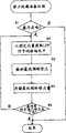
Fig. 6 is the process flow diagram that modified profile is prepared processing; With
Fig. 7 is the process flow diagram that shows the tilt correction process.
Embodiment
Now, explain the preferred embodiments of the present invention with reference to the accompanying drawings.Under the situation of the CD that is formed with pre-hole such as DVD-R and DVD-RW etc. on it, cheating in advance between the amplitude level of signal and the dish tilt quantity has correlativity.For this reason, in this embodiment, the dish tilt quantity detects and tilt correction is carried out by utilizing pre-hole signal.
Schematically show the dish that is formed with pre-hole on it among Fig. 1 and cheated relation between the signal in advance.Dish 1 for example is DVD-R or DVD-RW, and radially upper groove (groove) Gr of dish 1 and plane (land) Ld on recording surface alternately, form twist.Groove Gr is as the recording track of recorded information, and plane Ld forms between adjacent groove Gr.On the Ld of plane, (after this being called " LPP ") rule formation according to appointment is cheated on the plane in advance.This plane is cheated LPP in advance and is comprised the address information of coiling on 1.Particularly, the address information of the address of the groove Gr that determines on the display disc 1 is registered as the LPP that forms on the plane Ld outside this groove Gr that determines.
This LPP can be detected by quadruple optical detector PD shown in Figure 1.This quadruple optical detector has four detecting element A to D, and their output detection signal Sa are to Sd, and these signals obtain by the opto-electronic conversion from the light-receiving amount of dish 1.The detection signal Sa of output carries out computing to Sd by 3 totalizers 41 to 43 from detecting element A to D, and the LPP signal is produced.This LPP signal is provided by following equation:
LPP signal=(Sa+Sd)-(Sb+Sc) (1)
This quadruple photoelectric detector is installed in the pick-up of signal recorder or signal reproducing apparatus.This LPP signal is the pre-hole signal of the existence of indication LPP, it obtains to Sd, the computing finished according to equation (1) by using detection signal Sa under the situation below, that is: the detecting element A of quadruple photoelectric detector PD, D and element B, the border between the C is provided by the tracking servo device that provides in information-recording apparatus or the information reproduction device by the center of this recording track (groove) Gr.
This LPP be present within the recording track Gr and outside the plane on.According to equation (1), the LPP that is positioned at outside the recording track Gr is detected as negative detection signal, and the LPP that is positioned within the recording track Gr is detected as positive detection signal.
Can recognize that from equation (1) this LPP signal obtains by the push-pull signal (i.e. push-pull signal radially) at the radial direction of quadruple photoelectric detector PD.A kind of like this correlativity is arranged in logic, that is: when from the angle between the recording surface of the direction of illumination of the light beam of pick-up and dish during away from normal condition, just when the dish tilt quantity became bigger, the amplitude level of LPP signal became littler.And when the dish tilt quantity becomes more hour, the amplitude level of LPP signal becomes bigger.
The measurement result of mutual relationship shows in Fig. 2 between the amplitude level of such tilt quantity and LPP signal.As shown in Figure 2, amplitude level is big more, and the dish tilt quantity is more little, and in the position of the amplitude level maximum of LPP signal, the dish tilt quantity is almost nil.Notice that shifted by delta F is included in this result of experiment.Because when between the amplitude level of dish tilt quantity and LPP signal such mutual relationship being arranged, so certainly, it is maximum that the amplitude level of LPP signal should keep, so that the holding tray tilt quantity is zero.Notice that the shifted by delta F among Fig. 2 depends on experimental system, therefore, in actual correction, if tilt correction quantity is adjusted to eliminate side-play amount, then this side-play amount is inessential.
Fig. 2 also shown the dish tilt quantity with respect to from examine and seize the amplitude level of RF signal and relation between the amount of jitter.From Fig. 2 be appreciated that RF signal and the correlativity of dish between the tilt quantity almost with LPP signal and dish tilt quantity between correlativity identical.As for amount of jitter, to coil tilt quantity certainly and become more little, it is more little that this amount of jitter just becomes.
In this embodiment, based on the correlativity between the amplitude level of dish tilt quantity and LPP signal, the detected and tilt correction of this dish tilt quantity is performed.The illustrative configurations of Declination calibrating device shows in Fig. 3.
In Fig. 3, dish 1 is rotated with predetermined linear velocity by Spindle Motor 6.In order to write down and/or to reproduce, pick-up 2 with light beam irradiates to dish 1 and receive back light.Pick-up 2 comprises quadruple photoelectric detector PD shown in Figure 1, and the detection signal Sa that it also will be exported from each detecting element A to D offers LPP signal generation unit 3 to Sd.
The LPP signal generation unit 3 that comprises totalizer 41 to 43 shown in Figure 1 produces the LPP signal according to equation (1), and the LPP signal is offered tilt correction quantity determining unit 4.Tilt correction quantity determining unit 4 waits the amplitude level that detects the LPP signal by the level holding circuit.Utilize the correlativity between the amplitude level of this dish tilt quantity and LPP signal, it is zero required optimum tilt correction quantity that this tilt correction quantity determining unit 4 determines to make the dish tilt quantity.Then, the optimum tilt correction quantity that will determine like this of this tilt correction quantity determining unit 4 offers the tilt correction unit 2a in the pick-up 2.
By adjust the direction of illumination of light beam according to the optimum tilt correction quantity of input like this, this tilt correction unit 2a carries out tilt correction.Therefore, by utilizing the LPP signal, the detection and the tilt correction of dish tilt quantity just can be performed.
[embodiment]
The preferred embodiment of embodiment above will explaining now.
(1) information record and reproducer
Fig. 4 is the figure that determines that shows according to the illustrative configurations of information record of the present invention and reproducer.As shown in Figure 4, dish 1 is rotated with constant linear velocity by Spindle Motor 6.In Fig. 4, information record and reproducer 100 have record data are recorded register system 30 on the dish 1, the playback system that is recorded data 32 on the reproduction dish 1 and the Declination calibrating device 50 of execution tilt correction.This register system 30 and playback system 32 can dispose in mode well known in the art, so, omitted explanation at this to them.
The tilt correction unit 2a that this Declination calibrating device 50 comprises pick-up 2, LPP signal generation unit 3, the lowest point holding circuit 11, microcomputer 12, is used for the driver 13 of tilt correction unit and forms on pick-up 2.Tilt correction unit 2a can be made of various Declination calibrating devices, for example mechanically adjusts mechanism, the device that utilizes liquid crystal cell or the driver of the optical axis that shines the light beam on the dish.The storer 12a that is used for storing modified profile provides at microcomputer 12.
(2) Declination calibrating device
The operation of Declination calibrating device 50 will be described below.This pick-up 2 has quadruple photoelectric detector PD shown in Figure 1, and the detection signal Sa that will export from each detecting element A to D offers LPP signal generation unit 3 to Sd.This LPP signal generation unit 3 comprises totalizer shown in Figure 1 41 to 43, and produces the LPP signal and the LPP signal is offered the lowest point holding circuit 11 according to equation (1).
The lowest point holding circuit 11 keeps the lowest point level of LPP signal and this level is offered microcomputer 12.Microcomputer 12 utilizes the level of input like this to carry out tilt correction.
Be stabilized detected position at the LPP signal, the lowest point holding circuit 11 keeps the level of LPP signal.Particularly, this position is the non-posting field of (a) dish, or (b) compartment of dish posting field, or (c) at data recording compartment of record data during the dish.Fig. 5 A to Fig. 5 C shown from examine and seize the example of LPP signal waveform.Fig. 5 A has shown the LPP signal waveform that obtains during the non-posting field of reproduction dish, Fig. 5 B has shown the LPP signal waveform that obtains during the posting field of reproduction dish, and Fig. 5 C has shown the LPP signal waveform that obtains during disc recording information.The scale of the Z-axis of the amplitude level of indication LPP signal shows by 10 among Fig. 5 A and Fig. 5 B and shows among Fig. 5 C.
Shown in Fig. 5 A, at the non-posting field of dish, because record mark (pre-hole) is not also in the last formation of recording track (groove) Gr, so detection signal only comprises the variation corresponding to the amplitude level of LPP.
On the other hand, at the posting field of dish, record mark forms on recording track Gr, makes this LPP signal influenced by this record mark.As a result, shown in Fig. 5 B, the amplitude level of LPP signal becomes littler, and compares with the waveform shown in Fig. 5 A, and this waveform itself is out of shape.In brief, this LPP signal is unsettled at posting field, because the RF signal content of record data is included in the LPP signal.
When recording information on the dish, different with (wherein shining the light beam that reads of the firm power) situation of reproducing, shine light beam on the dish by the recording impulse sequence modulation, this sequence comprises according to the pulse train of writing strategy that is used to write down.For this reason, the influence that the amplitude level of the LPP signal that produces based on the luminous flux that returns from dish is changed by the level of recording impulse sequence, and shown in Fig. 5 C, become unstable.In Fig. 5 C, because more powerful light beam is shone by the smpa pulse in the recording impulse sequence (top-pulse), so it is bigger that the back light flux also becomes, and the amplitude level of LPP signal is approximately under the situation of the non-posting field shown in Fig. 5 A ten times (therefore, the Z-axis among Fig. 5 C is shown as ten times of scale among Fig. 5 A and Fig. 5 B).That is, the LPP signal waveform also is unsettled during writing down.
Therefore, in this embodiment, as noted above, the lowest point holding circuit 11 forms for the amplitude level that keeps the LPP signal, and (a) at the non-posting field, (b) of dish at the compartment of dish posting field with (c) at the compartment during the dish record, the lowest point circuit 11 is used for tilt correction with this amplitude level.Like this, because the LPP signal can obtain, and tilt correction can be only carries out based on this LPP signal when the level equalization of LPP signal, so can carry out the appropriate tilt correction.
Notice that Fig. 5 A has shown that to Fig. 5 C the polarity of LPP signal becomes the situation of negative polarity in the LPP part.In these cases, the absolute value of the amplitude level of LPP signal is confirmed as optimum tilt correction quantity to the tilt correction quantity that it becomes maximum.
And for the tilt correction during the record, when record was carried out synchronously with LPP, the lowest point holding circuit 11 was preferably in the 14T interval and keeps the LPP signal level.Reason is that this LPP signal level is stable at 14T at interval because 14T gap periods at interval is long, and with the situation of LPP synchronous recording under have higher probability and be: LPP is present in 14T interval location place.
(3) tilt correction
Above-mentioned processing is carried out in a plurality of zones of microcomputer 12 on dish, obtains optimum tilt correction quantity in each zone, and it is stored among the modified profile storer 12a.For can being divided into a plurality of zones by ad hoc approach by the whole posting field that will coil, its unit area of storing an optimum tilt correction quantity defines.For example, thoughtful periphery is divided into three or four parts (for example, by leaving the distance of disk center) the whole posting field of dish can make progress from it in the footpath of dish in, and can determine and store optimum tilt correction quantity for each is regional.
When the amplitude level that obtains the LPP signal along with changing tilt correction quantity is determined optimum tilt correction quantity, preferably utilize the amplitude level of the LPP signal corresponding with same LPP.As for DVD-R and DVD-RW, though in the size standardization in advance in the pre-hole that the recording surface of dish forms, the size in the actual pre-hole that forms often can be different on actual dish, even it is in this standard.Therefore, if use the LPP signal of the position acquisition that varies in size in pre-hole, then optimum tilt correction quantity can not correctly be obtained.Therefore, in definite processing procedure of optimum tilt correction quantity, microcomputer 12 repeatedly detects the corresponding LPP signal of LPP of going up the same area with this dish, and determines it is obtained the optimum tilt correction quantity of peak swing level.
The same area can be for example same recording track, same address or same section on the dish of pointing out above.That is to say that by obtaining the amplitude level of the LPP signal corresponding with same LPP or a plurality of same LPP, optimum tilt correction quantity is detected.Especially, repeat the track redirect or keep halted state in same address or always obtain the amplitude level of the LPP signal corresponding with same LPP by the same section that repeats to read predetermined length on same recording track by control pick-up 2, microcomputer 122 repeatedly reads same address.Microcomputer can repeatedly obtain the amplitude level of LPP signal for same tilt correction quantity, and can utilize the mean value of those amplitude levels when determining optimum tilt correction quantity.Therefore, microcomputer 12 can be eliminated the The noise of temporary transient generation.
According to above-described processing procedure, for prior each in a plurality of zones of definition on dish, the optimum tilt correction quantity of the amplitude level maximum (even dish tilt quantity minimum (zero)) of LPP signal is stored among the modified profile storer 12a in the microcomputer 12.After this, at the record and/or the reproduction period of dish, microcomputer 12 is controlled this tilt correction unit 2a execution tilt correction according to the optimum tilt correction quantity that is stored among the modified profile storer 12a.
(4) modified profile is prepared processing procedure
Next prepare the process of processing with reference to figure 6 explanation modified profiles.Fig. 6 is the process flow diagram that modified profile is prepared processing.The modified profile that shows among Fig. 6 is prepared to handle and is finished according to the control of microcomputer 12, for example when dish is placed into information record and reproducer 100.
At first, microcomputer 12 has determined whether that dish is placed into information record and reproducer 100 (step S1).This step is for example carried out by microcomputer 12, and microcomputer 12 obtains signal from the testing mechanism of dish.
When dish had been placed, microcomputer 12 was controlled pick-ups 2 and is obtained LPP signal (step S2) from coiling preposition.As noted above, it is in a plurality of zones one that this preposition is divided under the situation in several zones at the posting field of dish.Then, along with the variation of tilt correction quantity, this microcomputer 12 repeatedly obtains the amplitude level of the LPP signal of that position, and the tilt correction quantity of the amplitude level of definite LPP signal when becoming maximum, promptly optimum tilt correction quantity (step S3).Then, microcomputer 12 stores the optimum tilt correction quantity that obtains like this among the modified profile storer 12a (step S4) into together with positional information.
Whether next, microcomputer 12 is determined to have obtained optimum tilt correction quantity (step S5) in the presumptive areas all on dish.If all obtained optimum tilt correction quantity in all zones, then this processing procedure finishes.On the other hand, if optimum tilt correction quantity is not to obtain in all zones, thereby this processing procedure is got back to the step of step S2 repetition S2 to S4, and microcomputer 12 obtains optimum tilt correction quantity and stores it in next predetermined zone.Like this, when all having obtained optimum tilt correction quantity for all presumptive areas on the pre-determined dish, this processing procedure finishes.
(5) tilt correction is handled
Next, the tilt correction carried out of the modified profile that utilizes above-mentioned modified profile to prepare to handle to obtain is handled and will be made an explanation with reference to figure 7.Fig. 7 is the process flow diagram that shows the tilt correction processing procedure.This tilt correction is handled by microcomputer 12 and is carried out, and these microcomputer 12 controls are used for the driver 13 and the tilt correction unit 2a of tilt correction.
At first, microcomputer 12 determines whether make (step S11) by the user to the dish recorded information or from the instruction of dish information reproduction.If record or the instruction of reproducing are made, microcomputer 12 is the address (step S12) by the target location that utilizes LPP etc. to obtain record or reproduce just, and obtains optimum tilt correction quantity (step S13) corresponding to this address from the modified profile storer.In addition, microcomputer 12 controls are used for the driver 13 of tilt correction unit and carry out tilt correction (step S14) according to the optimum tilt correction quantity that obtains like this.Notice that step S12 carries out in record or reproduction process to S14.
Subsequently, microcomputer 12 determines whether the user makes the END instruction (step S15) of end record or reproduction.Step S12 repeats to S14, up to this END instruction of input.When END instruction was imported, this processing procedure finished.
[correction]
In the above embodiments, explained that modified profile is prepared to handle by modified profile shown in Figure 6 to prepare in advance and store, also explained at record that coils or reproduction period and utilized modified profile execution tilt correction.Yet, even without preparing modified profile, the amplitude level of LPP signal also can be during record or reproduction dish based on obtaining in real time, and, thereby tilt correction can be performed and makes the amplitude level maximum that obtains like this.Under these circumstances, in recording process, the amplitude level of LPP signal obtained in interim of record data, preferably in 14T interim.In the reproduction process, the amplitude level of LPP signal obtains at non-posting field or at the compartment of posting field.
In the above embodiments, the amplitude level of LPP signal is detected by the lowest point holding circuit 11.Under the sort of situation, the amplitude level of the LPP signal outside the recording track Gr is detected by quadruple photoelectric detector PD shown in Figure 1.Alternatively, tilt correction quantity also can be determined by the amplitude level that the LPP signal within peak holding circuit rather than the lowest point holding circuit 11 and the detection record track Gr is provided.And the amplitude level of the LPP signal that recording track Gr is inside and outside also can be by not only providing peak holding circuit but also provide the lowest point holding circuit to obtain.
Prepare in the processing procedure at above-mentioned modified profile, the LPP signal on the optimum tilt correction quantity utilization dish in the All Ranges calculates.That is to say that the tilt correction quantity when the detected and amplitude level of the amplitude level of LPP signal becomes maximum is confirmed as optimum correction.Alternatively, since the RF signal can obtain in the zone as the readable raised zones of writing zone, DVD-RW in advance of DVD-R and the zone of having write down etc., utilize the amplitude level of RF signal rather than the amplitude level of LPP signal so, also can determine optimum tilt correction quantity.As shown in Figure 2, about RF signal and dish tilt quantity, such mutual relationship is arranged also, that is: when the dish tilt quantity was zero, the amplitude level of RF signal became maximum.Therefore, in the zone that can obtain the RF signal of pointing out in the above, by detecting the amplitude level of the RF signal that changes with tilt correction quantity, the tilt correction quantity the when amplitude level of RF signal becomes maximum can be confirmed as optimum tilt correction quantity.
As mentioned above, in this embodiment,, make amplitude level become maximum thereby carry out tilt correction according to the amplitude level of the LPP detection signal (being the LPP signal) that on dish, writes down in advance.Therefore, tilt correction can be performed under the situation of large-sized special-purpose inclination sensor not having.
And, in the present embodiment, because the LPP signal is used to detection dish tilt quantity, so can acquisition dish tilt quantity by carrying out tracking servo.Therefore, advantageously: the dish tilt quantity not only can detect by preparing modified profile, and also can detect in recording process, in the reproduction process or even in halted state.
In addition, in the present embodiment, do not use to be used for the detection light of detection dish tilt quantity specially, the latter uses usually and is utilizing under the situation of special-purpose inclination sensor.When utilizing so special-purpose inclination sensor, has mistake in the concurrency between special-purpose tilt detection light and recoding/reproduction light.Given this situation in the above embodiments, is utilized the LPP signal to detect dish and is tilted, and this LPP signal is based on to the information record and/or reproduces that the back light that shines the light on the dish obtains.Therefore, different with the situation that adopts special-purpose inclination sensor, because the mistake of pointing out above that causes owing to concurrency can not take place, increased so coil the accuracy of detection that tilts.
The present invention can implement by other form under the situation that does not depart from its spirit or essential characteristic.Therefore, present embodiment is seen from which aspect all is considered to example rather than restriction, scope of the present invention is by the indication of appended claim, rather than by the above stated specification indication, and thereby all changes in the full scope of equivalents of claim be included in wherein.
The application number of submitting on June 19th, 2002 is the whole open text of the Japanese patent application of 2002-178529, comprises instructions, claim, accompanying drawing and summary, all is incorporated herein by reference.
Claims (6)
1. the Declination calibrating device with the dish that is formed with pre-hole thereon (50), described Declination calibrating device comprises:
Light source, it arrives light beam irradiates on the dish (1);
Quadruple photoelectric detector (PD);
Signal generation unit (3) is cheated on the plane in advance, and it produces the plane whether this pre-hole of indication exist based on the light that returns from this dish and cheats signal in advance, and it is push-pull signal on quadruple photoelectric detector radial direction that signal is cheated on this plane in advance;
Correction determining unit (4), it is cheated signal in advance based on described plane and determines optimum tilt correction quantity; With
Tilt correction unit (2a), it carries out tilt correction based on described optimum tilt correction quantity, and wherein correction determining unit (4) comprising:
The amplitude level detecting unit, it is by repeatedly detecting the amplitude level of cheating signal corresponding to the plane in same pre-hole in advance along with the same area place on dish changes the slant correction amount, and is that a plurality of tilt correction quantity detect the amplitude level that signal is cheated on this plane in advance; And
Determining unit, it becomes maximum tilt correction quantity to amplitude level to it and is defined as optimum tilt correction quantity.
2. according to the Declination calibrating device (50) of claim 1, the non-posting field detected amplitude level of wherein said amplitude level detecting unit on dish.
3. according to the Declination calibrating device (50) of claim 1, wherein at the posting field on the reproduction dish with when recording on the dish, described amplitude level detecting unit is at the compartment detected amplitude level of recorded information.
4. according to the Declination calibrating device (50) of claim 1, wherein said amplitude level detecting unit comprises level holding circuit (11), and this level holding circuit detects the peak level and/or the lowest point level in pre-hole.
5. according to the Declination calibrating device (50) of claim 1, also comprise: for coiling the storage unit (12a) of the optimum tilt correction quantity of each area stores in a plurality of zones, tilt correction is carried out based on the optimum tilt correction quantity that is stored in this storage unit in wherein said tilt correction unit (2a).
6. inclination correction method with the dish that is formed with pre-hole thereon, described inclination correction method comprises:
With light beam irradiates to the dish on process;
Produce the process that signal is cheated on plane that whether this pre-hole of indication exist in advance based on the light that returns from this dish, it is push-pull signal on quadruple photoelectric detector radial direction that signal is cheated on this plane in advance;
Cheat the process that signal is determined optimum tilt correction quantity in advance based on described plane; With
Based on the process of described optimum tilt correction quantity execution tilt correction, determine that wherein the process of optimum tilt correction quantity comprises:
The amplitude level testing process, it is by repeatedly detecting the amplitude level of cheating signal corresponding to the plane in identical pre-hole in advance along with the same area place on dish changes the slant correction amount, and is that a plurality of tilt correction quantity detect the amplitude level that signal is cheated on this plane in advance; And
Deterministic process, it becomes maximum tilt correction quantity to amplitude level to it and is defined as optimum tilt correction quantity.
Applications Claiming Priority (3)
| Application Number | Priority Date | Filing Date | Title |
|---|---|---|---|
| JP178529/2002 | 2002-06-19 | ||
| JP178529/02 | 2002-06-19 | ||
| JP2002178529A JP2004022127A (en) | 2002-06-19 | 2002-06-19 | Tilt correcting device |
Publications (2)
| Publication Number | Publication Date |
|---|---|
| CN1472733A CN1472733A (en) | 2004-02-04 |
| CN1294570C true CN1294570C (en) | 2007-01-10 |
Family
ID=29717491
Family Applications (1)
| Application Number | Title | Priority Date | Filing Date |
|---|---|---|---|
| CNB031490379A Expired - Fee Related CN1294570C (en) | 2002-06-19 | 2003-06-19 | Declination calibrating device |
Country Status (4)
| Country | Link |
|---|---|
| US (1) | US20040037195A1 (en) |
| EP (1) | EP1376550A3 (en) |
| JP (1) | JP2004022127A (en) |
| CN (1) | CN1294570C (en) |
Families Citing this family (8)
| Publication number | Priority date | Publication date | Assignee | Title |
|---|---|---|---|---|
| JP3975139B2 (en) * | 2002-08-30 | 2007-09-12 | パイオニア株式会社 | Tilt correction device and tilt correction method |
| TWI228253B (en) * | 2003-08-13 | 2005-02-21 | Mediatek Inc | Method for real time calibrating tilt control value of a pickup |
| JP4470695B2 (en) * | 2004-11-04 | 2010-06-02 | 船井電機株式会社 | Optical disc recording / reproducing apparatus |
| JP4556675B2 (en) * | 2005-01-14 | 2010-10-06 | 船井電機株式会社 | Tilt adjusting device and tilt adjusting method |
| JP4816033B2 (en) * | 2005-12-01 | 2011-11-16 | 船井電機株式会社 | Optical disc recording / reproducing apparatus |
| CN101331544A (en) * | 2005-12-13 | 2008-12-24 | 皇家飞利浦电子股份有限公司 | Method of lens positioning for tilt compensation, method and apparatus for reading and recording data onto an optical disc |
| JP2009146529A (en) * | 2007-12-17 | 2009-07-02 | Sharp Corp | Method for detecting servo parameter and optical pickup device utilizing the same |
| WO2012140832A1 (en) * | 2011-04-13 | 2012-10-18 | パナソニック株式会社 | Optical disc device and control method for same |
Citations (4)
| Publication number | Priority date | Publication date | Assignee | Title |
|---|---|---|---|---|
| CN1264897A (en) * | 1999-02-22 | 2000-08-30 | 三菱电机株式会社 | Disc device |
| CN1277712A (en) * | 1998-09-14 | 2000-12-20 | 松下电器产业株式会社 | Tilt detection device, optical disc device, and tilt control method |
| JP2001056949A (en) * | 1999-06-10 | 2001-02-27 | Sony Corp | Recording medium driving device and tilt detecting method |
| EP1213712A2 (en) * | 2000-12-01 | 2002-06-12 | Pioneer Corporation | Device and method for controlling tilt servo |
Family Cites Families (6)
| Publication number | Priority date | Publication date | Assignee | Title |
|---|---|---|---|---|
| JP3736666B2 (en) * | 1999-04-14 | 2006-01-18 | パイオニア株式会社 | Tilt servo device and control method |
| US6526007B1 (en) * | 1999-06-10 | 2003-02-25 | Sony Corporation | Recording medium driving device for rotationally driving a disk-shaped recording medium having tilt detection means and tilt detection method |
| JP3929207B2 (en) * | 1999-07-08 | 2007-06-13 | パイオニア株式会社 | Pre-pit detection device for optical recording medium |
| JP2002008246A (en) * | 2000-06-20 | 2002-01-11 | Sony Corp | Disk-like recording medium, disk recording and/or reproducing device and method, and tilt detecting method |
| JP2002133714A (en) * | 2000-10-23 | 2002-05-10 | Pioneer Electronic Corp | Multi-layer information recording medium and recording device |
| JP2002170266A (en) * | 2000-12-01 | 2002-06-14 | Pioneer Electronic Corp | Tilt servo controller and tilt servo control method |
-
2002
- 2002-06-19 JP JP2002178529A patent/JP2004022127A/en not_active Abandoned
-
2003
- 2003-06-18 US US10/463,350 patent/US20040037195A1/en not_active Abandoned
- 2003-06-19 CN CNB031490379A patent/CN1294570C/en not_active Expired - Fee Related
- 2003-06-19 EP EP03253884A patent/EP1376550A3/en not_active Withdrawn
Patent Citations (4)
| Publication number | Priority date | Publication date | Assignee | Title |
|---|---|---|---|---|
| CN1277712A (en) * | 1998-09-14 | 2000-12-20 | 松下电器产业株式会社 | Tilt detection device, optical disc device, and tilt control method |
| CN1264897A (en) * | 1999-02-22 | 2000-08-30 | 三菱电机株式会社 | Disc device |
| JP2001056949A (en) * | 1999-06-10 | 2001-02-27 | Sony Corp | Recording medium driving device and tilt detecting method |
| EP1213712A2 (en) * | 2000-12-01 | 2002-06-12 | Pioneer Corporation | Device and method for controlling tilt servo |
Also Published As
| Publication number | Publication date |
|---|---|
| CN1472733A (en) | 2004-02-04 |
| EP1376550A3 (en) | 2005-04-20 |
| US20040037195A1 (en) | 2004-02-26 |
| EP1376550A2 (en) | 2004-01-02 |
| JP2004022127A (en) | 2004-01-22 |
Similar Documents
| Publication | Publication Date | Title |
|---|---|---|
| CN1236433C (en) | Optical disk servo error detection method and its device | |
| CN1956073A (en) | Information recording medium | |
| JP2004030832A (en) | Optical disk recording device | |
| CN1294570C (en) | Declination calibrating device | |
| CN1739159A (en) | Radial position registration for a trackless optical disc surface | |
| CN1332447A (en) | Optical disk and its drive device | |
| CN1490797A (en) | Method and device for calibrating declination of light beam on optical recording media | |
| CN1122989C (en) | Information recording/reproducing apparatus | |
| CN1643365B (en) | Analysis apparatus and analysis disc used for the same | |
| CN1409306A (en) | Optic disc device | |
| CN1755824A (en) | Disk area detection method and equipment | |
| CN1297970C (en) | Optical pickup | |
| CN1224022C (en) | Oblique control for optical disk recording reproducing apparatus | |
| CN1440022A (en) | Device and method for determining differences between phase referrence signal and oscillation signals | |
| CN1825444A (en) | Information recording apparatus, information reproducing apparatus, information recording method, and information reproducing method | |
| CN1320530C (en) | Data recording device and its control | |
| CN1667715A (en) | Method of inter-layer search in a disk drive | |
| CN1950894A (en) | Motor transfer rate calibrated jumping | |
| CN1282966C (en) | Optical disc medium and optical disc recording/reproducing device | |
| CN101051484A (en) | Information storage medium and method and apparatus of recording and/or reproducing data on and/or from the same | |
| CN1906669A (en) | Optical disk recording method and optical disk recording and reading apparatus | |
| CN101075445B (en) | Disc device and platform prefabricated pit reproduction method | |
| CN1956069A (en) | Apparatus and method for accurately converting groove/land polarity on optical medium | |
| CN1495726A (en) | Actuator and optical head using the same | |
| CN1229238A (en) | Optical disk having pattern for tilt detection |
Legal Events
| Date | Code | Title | Description |
|---|---|---|---|
| C06 | Publication | ||
| PB01 | Publication | ||
| C10 | Entry into substantive examination | ||
| SE01 | Entry into force of request for substantive examination | ||
| C14 | Grant of patent or utility model | ||
| GR01 | Patent grant | ||
| C19 | Lapse of patent right due to non-payment of the annual fee | ||
| CF01 | Termination of patent right due to non-payment of annual fee |