CN1237460C - Computer with modular removable media drive - Google Patents
Computer with modular removable media drive Download PDFInfo
- Publication number
- CN1237460C CN1237460C CNB011170026A CN01117002A CN1237460C CN 1237460 C CN1237460 C CN 1237460C CN B011170026 A CNB011170026 A CN B011170026A CN 01117002 A CN01117002 A CN 01117002A CN 1237460 C CN1237460 C CN 1237460C
- Authority
- CN
- China
- Prior art keywords
- mainboard
- cabinet
- power supply
- storehouse
- media drive
- Prior art date
- Legal status (The legal status is an assumption and is not a legal conclusion. Google has not performed a legal analysis and makes no representation as to the accuracy of the status listed.)
- Expired - Fee Related
Links
Images


Classifications
-
- G—PHYSICS
- G06—COMPUTING; CALCULATING OR COUNTING
- G06F—ELECTRIC DIGITAL DATA PROCESSING
- G06F1/00—Details not covered by groups G06F3/00 - G06F13/00 and G06F21/00
- G06F1/16—Constructional details or arrangements
- G06F1/18—Packaging or power distribution
- G06F1/183—Internal mounting support structures, e.g. for printed circuit boards, internal connecting means
- G06F1/184—Mounting of motherboards
-
- G—PHYSICS
- G06—COMPUTING; CALCULATING OR COUNTING
- G06F—ELECTRIC DIGITAL DATA PROCESSING
- G06F1/00—Details not covered by groups G06F3/00 - G06F13/00 and G06F21/00
- G06F1/16—Constructional details or arrangements
- G06F1/18—Packaging or power distribution
- G06F1/181—Enclosures
-
- G—PHYSICS
- G06—COMPUTING; CALCULATING OR COUNTING
- G06F—ELECTRIC DIGITAL DATA PROCESSING
- G06F1/00—Details not covered by groups G06F3/00 - G06F13/00 and G06F21/00
- G06F1/16—Constructional details or arrangements
- G06F1/18—Packaging or power distribution
- G06F1/183—Internal mounting support structures, e.g. for printed circuit boards, internal connecting means
- G06F1/187—Mounting of fixed and removable disk drives
-
- G—PHYSICS
- G06—COMPUTING; CALCULATING OR COUNTING
- G06F—ELECTRIC DIGITAL DATA PROCESSING
- G06F1/00—Details not covered by groups G06F3/00 - G06F13/00 and G06F21/00
- G06F1/16—Constructional details or arrangements
- G06F1/18—Packaging or power distribution
- G06F1/183—Internal mounting support structures, e.g. for printed circuit boards, internal connecting means
- G06F1/188—Mounting of power supply units
-
- G—PHYSICS
- G06—COMPUTING; CALCULATING OR COUNTING
- G06F—ELECTRIC DIGITAL DATA PROCESSING
- G06F1/00—Details not covered by groups G06F3/00 - G06F13/00 and G06F21/00
- G06F1/16—Constructional details or arrangements
- G06F1/20—Cooling means
Abstract
A tower computer which includes a computer housing having a first bay with an access opening therein and a motherboard mounted in the bay opposite the access opening; a removable media drive mounted in the first bay which has a normal operating position in which access to at least a portion of the motherboard is blocked by the drive and a displaced position in which access is not blocked; the removable media drive being readily-displaceable between the normal operating position and the displaced position.
Description
Technical field
The present invention is relevant with computing machine, specifically, relate to a kind of have one be installed in a modular removable media drive in the mainboard storehouse make mainboard and driver can be conveniently enough and the computing machine of vertical configuration.
Background technology
Introduced before about 20 years since the personal computer constantly at the cabinet or " the machine box " that reduce to hold the basic computer parts such as mainboard, power supply and various driver.One of them reason is that computer peripheral has become day by day and can obtain and can bear, and therefore will compete desk-top space with computing machine.For example, for a modern computer users, it has not been rare that a computing machine, mouse, keyboard, 21 inches monitors, personal printer and scanners are arranged on his desktop, and does not have whatever except a typewriter or counter on previous typical desktop in 20 years.
Now the designer generally adopts, and to reduce the technology that computing machine accounts for the desktop area be to adopt vertical configuration.The computer cabinet of standard has smaller height and bigger length and width, and vertical computing machine has smaller width and bigger length and height.
Yet, no matter be configuration standard or vertical, all there is the problem of a designer's of some test the ability of dwindling the computing machine size to need to consider.At first, there are all modern computer users of some functional parts all to think and to be contained in the desktop personal computers.Yes that to make computing machine carry out work necessary for mainboard and power supply module.Certain type program and data storage device also need.At present, the memory device of typical case's installation has normally the fixed medium driver and a removable media drive of hard disk.The most general removable media drive of installation is the CD-ROM drive such as CD or DVD driver, though other removable media drive such as removable disk drive also is installed sometimes.Therefore, computer cabinet must have living space and hold these parts.
A kind of machine element is installed in a designing technique in the little space is to improve the parts packing densities, that is to say these parts are assembled in the cabinet thick and fast together.Yet what also will consider is that more powerful CPU (central processing unit) and the high-speed driver that is necessary for modern computer provides suitable heat radiation.If component-assembled gets too intensive, heat radiation just becomes problem.The Another reason of considering not want intensive assembling is that the owner of computing machine wishes by make their upgrading computer for mainboard interpolation RAM (random access memory) chip and expansion card.What will consider in addition is that computing machine owner and the computing machine that must carry out warranty repair work are made producer and wished that computer configuration becomes enough easily and may need the various parts safeguarding or change in the computing machine term of life.In the cabinet of intensive assembling, often essential processing by trouble is pulled down one or more parts with some specific purpose tools and technology, the parts that can reach necessary test or change.
Therefore, be necessary to develop a kind of like this computing machine, it is compact, but still has enough mainboard easily that reaches, and upgrade or repair can be than being easier to.This computing machine also should be configured to form suitable air-flow, and mainboard is dispelled the heat.
Summary of the invention
The purpose of this invention is to provide a kind of computing machine that is installed in a modular removable media drive in the mainboard storehouse that has.Driver and mainboard are configured to enough to reach driver easily in this storehouse section and carry out maintain/repair/replacing, can reach enough easily also that mainboard is upgraded or maintain/repair/replacing.
Therefore, vertical type machine provided by the present invention comprises a computer cabinet with one first storehouse section, Duan Youyi the Hatch Opening in this first storehouse.Mainboard is installed in the first storehouse section, faces this Hatch Opening.A removable media drive is installed in the first storehouse section, and it has the normal operation position an of obstruction enough reaches mainboard by Hatch Opening at least a portion and have one and does not hinder this part the replacement position that enough reaches mainboard by Hatch Opening.Removable media drive is easy in this normal operation position and replaces between the position and move.
The present invention also provides a kind of vertical type machine with such computer cabinet, this computer cabinet has one first storehouse section, it has and is positioned to relative one first side surface part and one second side surface part, and first side surface part wherein is provided with a Hatch Opening.Mainboard base plate with first side surface part that the mainboard device is housed and second side surface part opposite with first side surface part is installed in this storehouse section over against Hatch Opening, and second side surface part of mainboard base plate is positioned to second side surface part next-door neighbour with the first storehouse section.A removable media drive is installed in the described first storehouse section, and it has the normal operation position an of obstruction enough reaches described mainboard base plate by Hatch Opening at least a portion and have one and does not hinder the replacement position that enough reaches this part of described mainboard base plate by described Hatch Opening.Removable media drive is a conveniently moving between this normal operation position and replacement position.
Provided by the present inventionly a removable media drive is installed in a method in the vertical type machine comprises the following steps: a mainboard is installed in the mainboard storehouse that of described computing machine has a Hatch Opening; And described removable media drive is installed in the section of described storehouse between the described Hatch Opening and described mainboard in the mode of conveniently moving.
The present invention also provides a kind of vertical type machine, and this vertical type machine comprises: one has the first storehouse section and a cabinet that is installed in the mainboard in this first storehouse section that can enter by a side plate door; And a modularization media drive that is installed in the first storehouse section, in this first storehouse section, there are not other media drives or power supply.
Description of drawings
In the accompanying drawings illustration an illustrative present preferred embodiment of the present invention, in these accompanying drawings:
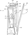
Fig. 1 is the left front birds-eye perspective of computer cabinet;
Fig. 2 is the just preceding birds-eye perspective of computer cabinet;
Fig. 3 is the right back birds-eye perspective of computer cabinet;
Fig. 4 is the right front birds-eye perspective of computer cabinet;
Fig. 5 pulls down positive back face upwarding view under the situation for computer cabinet at power module;
Fig. 6 is that computer cabinet is in the front, right perspective view under the situation that partially opens the position at the side door-plate;
Fig. 7 is in the open position right back skeleton view under the situation that power supply module partly pulls down for computer cabinet at the side door-plate;
Fig. 8 is in the open position detailed front, right perspective view under the situation that power supply module partly pulls down for computer cabinet at the side door-plate;
Fig. 9 is the detailed positive right skeleton view of computer cabinet under the situation that its door-plate is in the open position, and shows to be in the power supply module of partly pulling down state;
Figure 10 is in the open position right back skeleton view under the situation that power supply module partly pulls down for computer cabinet at the side door-plate;
Figure 11 is the detailed right back skeleton view of bottom under the situation that power supply module is taken one's seat of computer cabinet;
Figure 12 makes cam lever be in a detailed right back skeleton view under the situation that is driven the position for the bottom of computer cabinet disseats at power supply module;
Figure 13 is that the bottom of computer cabinet is in the detailed right back skeleton view under the situation of partly pulling down the position at power supply module;
Figure 14 is the detailed right back skeleton view of bottom after power supply module is pulled down of computer cabinet;
Figure 15 is the positive right face upwarding view at power supply module rear portion;
Figure 16 is the back birds-eye perspective of the power supply module of part decomposition;
Figure 17 is the detailed right birds-eye perspective of bottom under the situation that the side door-plate is in the open position of computer cabinet, shows the details of power storehouse;
Figure 18 is the right back face upwarding view of computer cabinet under the situation that the hard disk door is in the open position, hard disk is installed in Men Nei and power supply module is pulled down;
Figure 19 is in the open position the detailed rear view that Hard disc module is therefrom pulled down for the hard disk door;
Figure 20 is in the open position right face upwarding view under the situation that Hard disc module pulled down for the preceding bottom of computer cabinet at the hard disk door;
Figure 21 for the preceding bottom of computer cabinet the hard disk door be in the open position that Hard disc module is therefrom pulled down but still with situation that cable is connected under right face upwarding view;
Figure 22 for the preceding bottom of computer cabinet the hard disk door be in the open position that Hard disc module is therefrom pulled down and also fully with the situation of cable disengaging under right face upwarding view; And
Figure 23 is that the parts of a vertical type machine decompose the overview synoptic diagram.
Embodiment
Overview
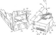
These accompanying drawings have disclosed a kind of computer cabinet 12, and generally speaking, this computer cabinet comprises: one by cabinet sidewall Hatch Opening 310 enterable first storehouse sections 300; One by cabinet rear wall Hatch Opening 572 enterable second storehouse sections 570; One by cabinet diapire Hatch Opening 741 enterable the 3rd storehouse sections 740.The first storehouse section 300 is suitable for installing an enough and mainboard 350 and be suitable for installing a modularization CD-ROM drive 410 easily.The second storehouse section 570 is suitable for installing a modular power supply assembly 510.The 3rd storehouse section 740 is suitable for installing a Modular Bay HDD assembly 710.
The outer matrix section of cabinet
Though below mentioned computer cabinet 12 roughly, will be described in detail cabinet and the machine element that is installed in the cabinet below.Fig. 1-5 illustration a kind of computing machine 10, it comprises a sheet metal cabinet 12 with outside surface 14 and inside surface 16.The center of cabinet is in the intersection of longitudinal axis X X, transverse axis YY and Z-axis ZZ.(so-called " level " and " vertical " are assumed to be the normal operation position of computing machine or slave unit here, except as otherwise noted.) sheet metal can be steel, wall thickness for example is 0.6 millimeter to 0.8 millimeter.The personnel that are familiar with this technical field are appreciated that also and can use the metal of other types and the wall thickness of other sizes.
Rear wall 24 (Fig. 3) extends laterally between rear wall/right wall vertical margin 90 and the rear wall/left wall, and vertically extends between apical margin 94 and the root edge 96.Rear wall comprises a top board 98 that cardinal principle is smooth, some is recessed for the first vertical margin lead-in that limits from the vertically extending flange section 106 of right wall of quilt and one second vertical margin lead-in 99, for example be 10 millimeters, these two vertical margin lead-ins all vertically extend with top board 98.Top board 98 has 110 and the 2nd I/O port zones 112 that are positioned at its middle part, first input and output at its top (" I/O ") port zone.Power module rear panel 114 (following also will illustrate) be positioned at panel part 98 and then below, and smooth following board 116 be positioned at power module rear panel 114 below.
The I/O port can comprise traditional port/connector, for example modem port 121, speaker port 122, game port 123, parallel port 124, monitor ports 125, mouse port 126, keyboard port 127 or the like are used for computing machine is connected with typical I/O equipment such as keyboard, display, scanner, joystick (all not shown).
Left side wall 26 (Fig. 1) has a panel part 162 that cardinal principle is smooth, except a ladder or lug boss 168, vertically extends to edge 38, vertically extends to root edge 164 from edge 142 from edge 92.End difference 168 has for example 5 millimeters front face 170 of a horizontal expansion, and for example 25 millimeters of the front wall panel 72 of the case of disembarking also have a similar rear face 174, from for example 25 millimeters of rear walls 24.It is the bottom surface sections of the extension of diapire 34 that end difference has a top part 176 and one.
Right side wall 28 (Fig. 4) has one vertically in extension between the edge 40 and 90, vertical at apical margin 144 and by hinge axes 194 be board 190 above extend between the border that the edge 196 of angled step shape limits smooth.Right side wall also comprises a smooth following board, except a configuration be positioned at opposite side wall 26 on the identical substantially projection/end difference 202 of lug boss 168, vertically extend between edge 40 and 90, vertical extension between the hinge axes on the apical margin of this bottom surface board 194 and edge 196 and root edge 200.
Can be clear that from Fig. 5 diapire 34 comprises a lordosis flat part 220, its center section laterally extends between protruding root edge 210 in a left side and right protruding root edge 212, and its front end extends between edge 164 and root edge 200.This lordosis panel stops at the hinder marginal part 222 with one second flat part, 230 overlappings, and second flat part 230 extends to trailing edge 96 in exposed exterior from edge 222.Lordosis panel 220 has some ventilating openings such as hole 232,234 etc. or seam bar (not shown), can comprise a recess 236, in the hole 766 that makes a screw 238 be contained in wherein to be opened (Figure 18).Can form right side recess 240,242, wherein have and can hold the hole of screw 244,246 that a hard disk is fixed to the inboard of panel 220, as following also to describe in detail.
In one embodiment, as shown in figure 23, cabinet 12 can comprise one first integral component 262, and it comprises the top of antetheca 22, left side wall 26, roof 32 and rear wall 24.Second parts 264 are formed by the upper and lower of hinged right side wall 28.The part of rear wall 24 is formed by the rear portion of power module 510.Another part of rear wall is formed by median septum parts 266.Parts 266 also contain the bottom of rear wall 24 and the part of diapire 34.The remainder of diapire is bottom door parts 268.These parts can connect with traditional sheet metal connection measure, and for example: lock flange, card is protruding is connected with nut with notch or other otch, screw and threaded hole or screw, riveted joint, finely weld, melting welding, or the like.
Cabinet can have following typical sizes: the a=105 millimeter, and the b=239 millimeter, the c=90 millimeter, the d=306 millimeter, the e=70 millimeter, the f=35 millimeter is shown in Figure 4 and 5.Be appreciated that these sizes are exemplary, show that here these sizes are suitable for being contained in the described dedicated computing thermomechanical components in other places.Certainly, if used machine element size is not inconsistent, if perhaps such machine element arrangement with specifically describe in illustrated embodiment that some is different, above typical sizes will change.For the machine element that holds size and the different machine element that specifically describes here or also will hold other changes these sizes, for former with regard to those skilled in the art that, be very easy after having read this explanation, therefore here no longer discuss.Be appreciated that the present invention is not limited to any above size, except the range of size of in one or more following claims, specially enumerating.
As shown in figure 23, cabinet 12 can be wrapped in highstrenghtpiston's shell 270 attractive in appearance.Plastic casing 270 can comprise a first 272 and a second portion that comprises right side wall 284 that antetheca 274, rear wall 276, left side wall 278, roof 280 and diapire 282 are arranged, to be fit to dismountable installation, as protruding by the release locking card of pushing on the side mouth 286 that is stuck in first.This shell can have some to open air vent in its top 290 and the bottom 294 of arching upward.Otch 296,298,299 on the shell 270 etc. is arranged to the front end face 412 that exposes removable media drive, rear end face 512 and each I/O port of power supply module.Best, shell be designed to for example use some keys in some sense and press that unfreezing is protruding, screw etc. so that make can very promptly pack into shell or split out of cabinet 12, for example in less than 30 seconds time from shell.Yet, be appreciated that, below said " modularization " be relative cabinet 12 with " enough and convenient ", do not consider anyly to split out cabinet 12 time of (if necessary) from shell 270 in time that any part of pulling down shell 270 may need or in order enough to reach specific features.
Mainboard storehouse section
As being clearly shown that the most from Fig. 6-10, computing machine 10 has mainboard and admits storehouse 300, and the Hatch Opening 310 of right flank 28 that can be by sheet metal cabinet 12 enters.This mouthful covered by an openable side plate door 312.Side plate door 312 can comprise sidewall upper flat plate portion 190 and flange portion 41,106,146 (Fig. 4).Shown among this embodiment, side plate door 312 is installed on the cabinet can pivot mode by the hinge portion on door 312 and the cabinet 12 314,316, and a pivot pin (not shown) that limits center of rotation PP is arranged in the hinge portion.The flange portion 106,146,41 of side plate door 312 when door is closed and the adjacent part of the back of cabinet, end face and front overlap.Near the flange portion 318,320,322,324,326 of these flange portion of door and the edge 328 that is positioned at Hatch Opening 310 cooperates.Specifically, when door was closed, these flange portion on the side plate door 312 made flange portion 318,320,322,324,326 be biased to position shown in Figure 7, are subjected to inside elastic force.Therefore, these flange portion surface of when door is closed, having adjacency of cabinet and door, and also the surface of these adjacency is pressed on together owing to the elastic restoring force of these two groups of flanges.As a result, between the surface of these adjacency, exist appreciable sliding friction, make in case just be maintained in its closed position after closing.In order to prevent that further door from opening, a screw 334 (Fig. 4) can be passed open hole 330 on door top flange 146 and be screwed in the threaded hole 332 on the cabinet top flange 320.Certainly, there are many doors to keep assembly or structure can be used for door is maintained in its closed position for example traditional case latch assembly, spring catch assembly, dogging assembly etc.
Fig. 9,10 and 23 the most clearly illustration a mainboard assembly 350, it comprises a base plate 352, the inner wall surface 353 of its back 355 and cabinet sidewall 26 is in abutting connection with installing.Base plate can be installed on the wall surface with classic method, for example uses screw, rivet etc.A central processing unit (CPU) 354 is equipped with at core in the front 357 of base plate 352.Dispose various circuit arrangements 356,358 etc. on the base plate 352, hold the expansion card notch 360,362 of expansion card 364,366 (Figure 23), hold the memory chip notch 368,370 of memory chip 372,374 etc.CPU radiator fan 376 can be directly installed on the CPU.These devices of mainboard assembly are sometimes referred to as " mainboard device " or " being installed in the device on the mainboard " here.
Various signal cables 378 and feed cable 380 stretch into mainboard storehouse section 300, are connected with mainboard assembly.Mainboard assembly can have dissimilar, and different size and shape are arranged.Shown among this embodiment, mainboard is the mainboard of Intel Micro ATX form factor, has rectangular shape, it highly is 190.5 millimeters (when being installed in the cabinet) that size is equivalent to, length is 216 millimeters.Mainboard storehouse section 300 preferably has and essentially identical length of mainboard and height, has almost and the identical width of cabinet width " c ", in this exemplary embodiments is 90 millimeters.The length of mainboard storehouse section is at least 1.5 with the ratio of width, preferablely is at least 2.0, and preferably is at least 2.5.Mainboard can be traditional electrical connection with being connected of various I/O ports, media drive, power supply etc.Except these different electrical connection cables, mainboard storehouse section 300 does not have other machine elements (for example just not having other machine elements except a media drive) basically, and therefore a bigger heat-dissipating space is provided in the section of storehouse.In some preferred embodiments, mainboard storehouse section 300 has 80% free space at least, more preferably has 85% free space at least, and best be that 89% ± 5% free space is arranged.
These metal wooden partitions around mainboard storehouse section 300 provide EMI shielding, and the protection mainboard assembly is not mechanically damaged, but also have formed a draft chamber that the heat radiation airflow is provided for mainboard assembly.
Removable media drive
A machine element that is positioned at mainboard storehouse 300 except that mainboard assembly 350 is a media drive assembly 410, is a removable media drive in illustrated this embodiment, for example has CD or the DVD CD drive of a pivot center RR.The center of this driver is in longitudinal axis X
1X
1, transverse axis Y
1Y
1With Z-axis Z
1Z
1Joining on.Axis RR is the horizontal cross configuration when driver is in normal operation position shown in Fig. 7 and 8.The front end face 412 of removable media drive 410 is placed in first mouthful 42 interior (Fig. 1 and 2) of antetheca 22.Front end face 412 can be a kind of front end face of accepting the driver of CD by a front notch, perhaps also can be shown in this embodiment, be the sort ofly to have one can stretch out (not shown) so that CD can be placed on the front end face of the driver of the vertical removable pallet on the drive spindle (not shown) from front end face.These two kinds of loading mechanisms are well-known in this technical field, here just no longer explanation.The vertical height of this driver front end face " j " can be for example 130 millimeters.
The rear end face 414 of driver can be equipped with a signal cable adapter 416 that removably is connected with signal cable 417 and a feed cable adapter 418 that removably is connected with feed cable 419.Fig. 8 shows the situation that driver 410 is connected to cable, and the situation that Fig. 7 shows these cables when removing.The longitudinal size " k " of the first and second horizontal sides 418,420 of driver can be 130 millimeters, and the lateral dimension " l " of end face 422 and bottom surface 424 can be for example 13 millimeters (Fig. 2).
Driver 410 is installed on the driver rack 432, and the main part 434 (Fig. 9) of driver rack 432 is vertical, longitudinal extension, near driver sidewall 420.Support 432 also comprises horizontally extending bottom 436, vertically extending lower panel portion 438 and the clubfoot portion 440,442 of stretching out from lower panel portion.Support also comprises upper panel portion 444 (Fig. 8) and the front end aligning fin 446,448 (Fig. 9) with a screw receiving opening.
Being fixed on driver top mounting flange 456 on the cabinet (for example forming one with cabinet) can have a screw hole 458, can aim at the screw hole in the upper panel portion 444, thereby can upper panel portion 444 be fixed on the flange 456 with a screw 460.Certainly, can adopt other dissoluble connection measure to replace this screw to connect, for example can adopt spring metal card (not shown) or the connection of dogging (not shown) etc.
The following clubfoot portion 440,442 of support 432 can slide and include notch 452,454 rotationally in.Clubfoot portion 440,442 and lower supporter 450 make on the mounting flange 456 time bottom of driver rack 442 and cabinet 12 keep stable static relation above upper panel portion 444 is fixed to driver.When liberating in the upper end, driver 410 can be that the center turns to cardinal principle horizontal level as shown in Figure 9 with axis HH with the support 442 that is connected.After this, if desired, driver laterally can be moved apart support 450 with the support that is connected 442, make foot 440,442 break away from notch 452,454 fully, therefore driver be unloaded from cabinet 12 with the driver rack 442 that is connected.Can with hand signal and power supply and voice-frequency cable 417,419 be thrown off behind from driver before or after separately from support 450 at driver, driver can be pulled down from cabinet fully, change, repair or the like (Figure 10).
It will be appreciated, of course, that driver be in as shown in Figure 9 be rotated the position of having moved or as shown in figure 10 fully by when cabinet is pulled down, the All Ranges of mainboard assembly 350 just can enough reach easily.Therefore, the user can be computing machine interpolation expansion card or storer rapidly, easily, and does not need to use specific purpose tool, does not also need technical skill or training.Similar, the technician can enough reach any part of mainboard assembly 350 rapidly, easily and test.Shown among this embodiment, do just: pull down screw 334 from the top of access door 312; According to direction 313 rotations door 312 is opened; Pull down screw 460 or liberation spring card or the like from driver rack fin 456; According to direction 413 rotary drivers; And if necessary pull down cable 417 and 419 with hand.Whole operation does not have the personnel of technical experience as long as once carried out can finishing usually of once operating so at least in three minutes for one.Therefore, whole mainboard is exactly enough reaching easily.Here when speaking of a machine element such as mainboard what is called " enough and easily " be used to refer to one do not have the ordinary person of technical experience if carried out once same operation recently at least just can in three minutes, not have obstacle ground enough to reach this machine element without specific purpose tool.Be appreciated that, this " enough and easily " is relative cabinet 12, do not consider any in time that any part of pulling down shell 270 may need or in order enough to reach specific features splits out cabinet 12 (if necessary) needs from shell 270 time.
Though the explanation of this embodiment shown in the above combination be horizontal pivot axis HH below situation, be appreciated that by relation just to be configured to the situation of horizontal pivot axis above being located at the other way around easily with each support element.In addition, be appreciated that, if will be mounted to leading section perpendicular line VV (Fig. 8) with driver as pivot axis such as 432 such driver racks, just can make driver is that pivot moves with such perpendicular line, thereby can reach and be placed in the mainboard device of driver 410 back.
Should be noted in the discussion above that when driver 410 is in normal operation position shown in Fig. 7 and 8 that its side 418 and side plate door 312 protrude in mainboard storehouse 300 with the size " l " of minimum in abutting connection with (when door is in off-position).Therefore, driver 410 does not hinder airflow by mainboard storehouse 300 basically in its normal operation position, that is to say that driver airflow rate by the mainboard storehouse when this position is at least 90% of the airflow rate of driver when pulling down fully.
In addition, driver 410 is to move easily to as shown in Figure 9 the position that does not hinder mainboard that can reach those parts after being positioned at driver on the mainboard when driver 410 is in its normal operation position from as shown in Figure 8 its normal operation position.Here the what is called of Shi Yonging " move easily " be meant one do not have the ordinary person of technical experience if carried out once same operation recently at least just can in three minutes, parts be moved to another position from a reference position without specific purpose tool.Be appreciated that, this " moving easily " is relative cabinet 12, do not consider any in time that any part of pulling down shell 270 may need or for specific features is moved to another position splits out cabinet 12 (if necessary) needs from shell 270 time from a position.
Driver 410 also is modular.Say that here a machine element is that one of these parts that are meant of " modularization " do not have the ordinary person of technical experience as long as recently carried out once just can pulling down fully without specific purpose tool of same operation at least in three minutes.What be appreciated that this " modularization " is relative cabinet 12, does not consider anyly to split out time of cabinet 12 (if necessary) needs from shell 270 in time that any part of pulling down shell 270 may need or in order to pull down specific features.Also use " convenient disassembly " or " convenient disassembly ground is installed " parts here with above meaning " modularization ".
Power supply module
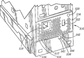
Fig. 3,7,9 and 11-16 clearly show that the power supply module 510 of computing machine 10 the most.Power supply module 510 comprises the assembly housing 512 of a parallelepiped shape, and its rear end face 514 forms a part 114 (Fig. 3) of cabinet rear wall 24 in normal operation position.As shown in figure 11, rear end face 514 is rectangular, and a plurality of air vents 516,517 etc. are arranged.It also has a power line socket 518, indication power work whether normal pilot lamp 520 and a general voltage selector switch 522, and these all are general, for well-known in this technical field.Assembly housing 512 has a more smooth rectangle front end face 524, and its bottom is equipped with a highdensity power supply connector 526, and its upper corner is equipped with an AC interlocker 528.Power supply connector and AC interlocker also are well-known in this technical field.
Have a plurality of airflow orifices 534 on the end face 532 of assembly housing 512.
Power supply module box 512 has a flat rectangular bottom surface 536, is rotatably mounted with a cam lever 538 (Figure 15) thereon.Cam lever 538 has a vertically extending pivot center CC and a vertically extending cam surface 540.Free end 543 at cam lever has formed one the first vertical tab portion 542 with second of vertical tab portion 541.First tab portion 541 has a through hole 544.Hole 544 be with the assembly housing rear wall parts on a corresponding hole 545 (Figure 14) can aim at.Cam lever 538 also has a vertically extending pin hole 546, can admit a latch key 548.Latch key 548 not really vertically is installed on the bottom surface 536, is supported by a cantilever tongue of metal that forms by the part cutting.
Power supply module box 512 also comprises the right flank 552 of a rectangle and the left surface 554 of a rectangle.In a typical embodiment, the longitudinal size of power supply or length " m " are 152 millimeters, and lateral dimension or width " n " are that 83 millimeters and vertical dimension or height " o " are 57 millimeters.The center of power supply is in longitudinal axis X
2X
2, transverse axis Y
2Y
2With Z-axis Z
2Z
2Joining.As Figure 16 was clearly shown that the most, modular power supply assembly 510 comprised a Power Supply Assembly 562, and it has various can be the appliance device 564 etc. of general power supply apparatus.Power supply module 510 also comprises a power supply heat sinking fan 566, is installed in the assembly housing 512.Best, these appliance device 564 grades are configured in the bottom of assembly housing, and radiator fan 566 is fixed on the wall of end face 532, makes the rotation of fan and the center longitudinal axis Z of power supply module
2Z
2Parallel.
When modular power was in normal operation position in power storehouse 570, attaching plug 526 just was inserted in the supply socket 580, and AC outage execute key 590 is inserted in the AC circuit breaker 528.This position is illustrated in Fig. 3 and 11, and the rear wall parts 510 of power supply module box flushes with lower panel 116 on this position.On this normal operation position, cam lever 538 is in power supply rear end face center and takes over, and its screw hole 544 is aimed at the screw hole 545 of wall of computer case 116.On plate 116, have recess 547, can admit first tab portion 541 of cam lever.In order to prevent to make the cam lever action unexpectedly, a screw (not shown) can be passed hole 544 and be screwed into threaded hole 545.Even without screw through hole 544 and 545, because the interaction of pin hole 546 and latch key 548, cam lever 538 also can remain on the position shown in Fig. 3 and 11.
In order to pull down modular power supply assembly 510 from power storehouse 570, can shown in the arrow among Figure 12 551, push away left with the right side of thumb in tab portion 542, make cam lever 538 actions.Hand reinforcing on direction 551 is enough to make latch key 548 to deviate from pin hole 546, therefore can move on direction 551.As Figure 12 and shown in Figure 7, the motion of cam lever on direction 551 makes cam surface 540 cooperate with cam post 575, and the power supply module 510 that connects is moved backward to the position shown in Figure 12 and 7.In this position, high density power supply plug 526 has just broken away from the respective socket 580 in the power storehouse, and AC circuit breaker 528 has moved to from AC outage key 590 and is enough to disconnect AC power supplies and connects.
Usually, the AC circuit breaker is arranged to disconnect much Zao than high density power supply plug.For example, the AC circuit breaker can just open circuit moving 2 millimeters backward, and high density connector 526 will break away from after moving 5 millimeter backward again.
Then, as shown in figure 13, can catch the external part of modular power supply assembly 510, it is pulled back into break away from power storehouse 570 fully.As Figure 14 is clearly shown that the most, can on these walls in storehouse 570, form a plurality of tongues 571,573 of inclined to one side longitudinal extension etc. in the storehouse slightly.The friction force that the size of modular power and power storehouse and each tongue 571,573 etc. are applied is designed to must be to the power of after-applied appropriateness, for example 5 pounds, just can make modular power break away from storehouse 570.Fig. 9 shows the situation that power supply module 510 is in a part disengaging configuration.Figure 14 shows the situation that power supply is pulled down in the storehouse fully.
Power supply is moved to shown in Figure 14 pulling down fully about 5 to 10 seconds of the time that the position need spend from the position of taking one's seat shown in Fig. 3 and 11.If must tear next screw open from cam lever, one does not have the ordinary person of technical experience approximately is 20 to 30 seconds as long as carried out once the required T.T. of power supply of pulling down of same operation recently at least.Therefore, power supply module 510 is one and meets above " modularization " implication " modularization " parts.
For modular power 510 being sent back to its working position, cam lever 538 is returned to the position shown in Fig. 3 and 11, thereby latch key 548 has just been included in the pin hole 546 in.After this, module 510 is inserted Hatch Opening 572, shift onto forward always and arrive the position of taking one's seat shown in Fig. 3 and 11.In this position of taking one's seat, high density power supply connector 526 is connected with socket 580, and AC interlock 528 and 590 engagements of AC outage execute key make this power supply be electrically connected with an AC power supplies that is connected by the power lead (not shown) that is inserted in the AC socket 518.If necessary, a screw (not shown) can be passed hole 544 and be screwed into hole 545, reliably modular power supply assembly 510 be remained on the position of taking one's seat shown in Figure 11.
Therefore, by each power supply device 564 and power supply heat sinking fan 566 are installed in the single power supply module box 512, when power supply being pushed in the storehouse 570 from being dynamically connected with hand automatic cutout during 570 dismantling powers from the storehouse, it is extremely easy that operating personnel will pull down the out of order power supply that power supply is checked and/or if necessary change with a new power supply.In order to pull down power supply module,, need not pull down or take apart by any way power supply module itself except having other any machine element.If, wish to check power supply appliance device 564 or fan 566 that will do just pulls down pair of screws 531 (in hole 535,537) and pull down pair of screws 539 from rear end face 524 from end face.Shown among this embodiment, power supply end face 532, rear end face 524 and side 552,554 usefulness single piece of metal plates form, and suitably are processed into shape shown in Figure 16.Pull down four screws and enough reach power supply module box 512 to need the time of cost approximately be 2 minutes, even more still less.Certainly, assembly housing 512 also can be with any sheet metal forming technology, comprise and form six faces that separate with mounting flange joint or the screw connection, perhaps form composite component with two or more, design is connected with being arranged to the appropriate section of adjacent surface, forms the assembly housing 512 of a parallelepiped shape.Even power supply module box 512 is torn inconvenience open, but still the very big advantage that has power supply module to pull down easily and to change.As long as the computer user therefore can return power supply module 512 easily rather than whole computing machine is guaranteed to keep in good repair or overhauled.In this structure, the information of third party on can his driver of unauthorized access needn't be worried about by the computing machine side of having, and does not also have in the face of encapsulating and load and transport the problem of whole computing machine spended time and spending.In addition, even whole computing machine 10 is returned to a warranty repair shop, also can change out of order power supply module 510 rapidly, easily, thereby save considerable labour cost for warranty repair shop and/or user's (if being non-warranty repair).
Configuration of modular power supply module 510 and power storehouse 570 is positioned to the advantage under mainboard storehouse 300 just is to carry out very effective heat radiation to power supply appliance device 564 and mainboard assembly 350 by the air-flow 592 (Fig. 7) that power supply fan 566 (for example tubeaxial fan of model No.ADO812MS of selling of Taiwan Adda and so on) and cpu fan 376 (can be the radial-flow fan of the model No.5ODC12V and so on of Taiwan Global Win production) forms like this.As Fig. 7 is clearly shown that the most, enter mainboard storehouse 300 from the rear end face 514 inflow power supply module boxes of power supply module box 512, the air-flow that flows out from end face 532 at the rear portion in mainboard storehouse 300, flow out the air vent 152,154 open on the end face 32 of computer cabinet 12 etc. by the mainboard storehouse, form current path 592.(perhaps, can the direction of fan is reverse, air-flow can enter from air vent on the end face 32 of cabinet 12 152,154 etc., through mainboard storehouse 300, flow into the power supply module boxes by the hole on the end face 532 of power supply module box 534, flow out air vent 516,517 on the rear end face 514 of power supply cabinet 512 etc. by power supply fan and power supply cabinet again.) can form this omnidistance current path with the air-flow of any one fan generation, just can improve airflow rate certainly with two fan works.The working condition of these two fans can each be controlled by a thermal switch with traditional mode, makes just to carry out work when only the temperature in the section of relevant storehouse arrives a predetermined temperature.
Hard disk drive (HDD) assembly
Hard disk drive (HDD) assembly 710 is installed in the hard disk drive storehouse 740 of bottom of computer cabinet 12.This Lower Hold has one can be pivotally supported wall portion 220 with axle DD, so that enough reach hard disk drive, shown in Fig. 5 and 18-22.As Figure 21 was clearly shown that the most, hard disk drive (HDD) assembly 710 comprised top part 712 opening, general rectangular, had threaded hole 713,715 on its incline 717.Actuator assembly 710 has the bottom surface 714 (Figure 18) of a general rectangular, the first horizontal side 716 of a general rectangular, the rear end face 720 of 718, one general rectangular in the second horizontal side of a general rectangular, and the front end face 722 of a general rectangular (Figure 21 and 22).The center of hard disk drive can be in longitudinal axis X
3X
3, transverse axis Y
3Y
3With Z-axis Z
3Z
3The intersection.The length of the longitudinal extension of hard disk drive (HDD) assembly " s " can be 100 millimeters, and the width of horizontal expansion " t " can be 145 millimeters, and vertically extending height " u " can be 21 millimeters (Figure 21).As Figure 20-22 is clearly shown that the most, the feed cable connection plug 726 of the feed cable 728 that the signal cable connection plug 724 that front end face 722 has a signal cable 725 that a receivability can connect with hand and a receivability can be connected with hand.Plug 724 and 726 be installed in driver circuit board 730 on pack into the device of hard disk drive 732 be electrically connected, these devices all are installed in the box that is limited by face 714,716,718,720 and 722.
Hard disk drive storehouse 740 is configured in the bottom of computer cabinet 12, and a normal closed position (Fig. 5) and an open position (Figure 18) are arranged.The hard disk drive storehouse is limited by roof 574 and diapire 220, and these two walls parallel when being in off-position in the hard disk drive storehouse.This storehouse is also limited by antetheca recess 72 (Fig. 1 and 2 2), left side wall flange 742, right side wall flange 744, the vertical flange 746 in a diapire left side and the right vertical flange 748 of diapire.As Figure 22 further illustrates, there is one owing to roof 574 does not reach the vertical openning 750 of front end that front wall portion 72 (for example from wall 72 about 70 millimeters) forms, the path that enters transfer chamber 581 from hard disk drive storehouse 740 is provided, makes signal and feed cable 725,728 can pass chamber 581 and enter hard disk drive storehouse 740.
As Figure 20 and 22 was clearly shown that the most, a pair of pivot pin 752,754 ran through the recess 757,759 of cabinet flange portion 760,762 and diapire flange 746,748 respectively.Pivot pin 752,754 is that pivot is installed to diapire storehouse access door 221 on the cabinet 12 with axis DD.
Except door 221 being maintained in its closed position reliably with screw 238, other device that door is maintained in its closed position can be set, for example can a positioning convex be set on the flange 776 and a positioning convex 778 is being set on flange 780.These two positioning convex cooperate with hole 782 (only showing) on flange 742 and 744 respectively.
Fig. 5 shows the situation that door 220 is in off-position, and the hard disk drive (HDD) assembly 710 that is installed in the hard disk drive storehouse 740 is on the working position.In order to take out hard disk drive, at first take off a gib screw 238 with common bottle opener 239.Then door is rotated around pivot DD, be opened to position shown in Figure 180.Again screw 244,246 is taken off, be put into surface upward (Figure 19 and 20) thereby hard disk drive (HDD) assembly 710 can be pulled down from door 220.Next as shown in figure 21, with hand signal cable 725 and service cable 728 are pulled down from corresponding plug 724,726.Now just hard disk drive can be pulled down (Figure 22) from computing machine 10 fully.Be appreciated that dismounting also can carry out in proper order with other.For example, can pull down screw 244,246 earlier and pull down screw 238 again, perhaps can take away cable earlier and pull down screw 244,246 again.From working position shown in Figure 5, pulling down 710 1 of hard disk drive (HDD) assemblies from computing machine 10 does not have the ordinary person of technical experience as long as carried out once same required T.T. of operating recently at least less than three minutes.Therefore, hard disk drive (HDD) assembly 710 is one and meets above " modularization " implication " modularization " parts.
A hard disk drive is reinstalled into computing machine and can be carried out with the opposite step of above explanation unloading process.Reinstall time that hard disk drive need spend substantially with to pull down the time that hard disk drive need spend suitable, less than three minutes.
Be appreciated that to a computing machine provides Modular Bay HDD assembly 710 as described above and many benefits all arranged for user and the both sides of Computer Service department.For example, if a user wishes to finish the work on the out of order hard disk drive, he can pull down this hard disk drive easily and be transported to the repairing place, and the considerable trouble that does not experience encapsulation and load and transport whole computing machine.In addition, he individual perhaps can be not having to continue his computing machine of use under the situation of this hard disk drive, if he has another to have the driver of the copy of this computer operating system.Another benefit is, if computer operator's requirement is served the other parts of his computing machine, he just can stay this hard disk drive sending computer again, so he can keep the control to this hard disk drive, perhaps contains sensitive data thereon.In addition, a user can use the same manner of removable media to use this removable disk drive with the computer user.For example, under the situation that a computing machine is shared by a plurality of users, each user can have and keep the special-purpose hard disk drive of he individual, oneself installs when beginning his work.Certainly, a removable disk drive is very favorable to maintenace point, can be easily for the user change out of order hard disk drive, and perhaps the user is just waiting use.The hard disk drive of this convenient disassembly has reduced the working time of hard disk drive maintenance or after service, therefore helps computer maintenance personnel and computer user.
Therefore, can see that the computing machine 10 that is provided is very compact, only takies smaller " support area " on the table.The embodiment cumulative volume of this cabinet that for example, more than specifically describes is less than 7143cm
3Yet, this various parts are installed in each parts that mode in the computing machine still is easy to enough reach computing machine, even such configuration is compact.Removable media drive, hard disk drive and power supply all are modular components, and the dismounting of these parts and replacing/maintenance/inspection all are easy to.This modular construction also makes the computer motherboard assembly enough reach conveniently, is convenient to maintenance and repair or upgrading.
Though more than describe exemplary currently preferred embodiments more of the present invention in detail, but be appreciated that, design of the present invention also can be embodied and utilized with various ways, so appended claims has been understood to include all the such modification except that prior art.
Claims (6)
1. a vertical type machine (10), described vertical type machine comprises:
Comprise the computer cabinet (12) of the first storehouse section (300) that is used to hold media drive, the described first storehouse section has a wall that wherein has Hatch Opening (310);
One be installed in the described first storehouse section (300), with a wall that the wall that has described Hatch Opening (310) parallels on mainboard (350), described mainboard faces described Hatch Opening (310);
A removable media drive (410) that pivotally is installed in the described first storehouse section (300), has an at least a portion that is covered with described mainboard (350), and hinder the normal operation position that enough reaches at least a portion of described mainboard (350) by described Hatch Opening, and has an at least a portion that does not cover described mainboard (350), and do not hinder the replacement position that enough reaches described at least a portion of described mainboard (350) by described Hatch Opening, described removable media drive (410) can move between described normal operation position and described replacement position.
2. the vertical type machine of claim 1 (10), described removable media drive (410) pivotally is fixed on the described cabinet (12) at its one first end (424), and is fixed on the described cabinet (12) in the mode that can unclamp at its one second end (422).
3. the vertical type machine of claim 1 (10), described removable media drive (410) it one first end (424) pivotally and the mode that can unclamp be fixed on the described cabinet (12), and be fixed on the described cabinet (12) in the mode that can unclamp at its one second end (422).
4. the vertical type machine of claim 1 (10), described vertical type machine also comprises a driver rack (432) with at least one clubfoot portion (440), described removable media drive (410) is fixedly mounted on the described support (432), can move with it, by described driver rack (432) and described computer cabinet (12) can unclamp be connected, described driver (410) is removably mounted in the described first storehouse section (300).
5. the vertical type machine of claim 1 (10), described mainboard (350) is equipped with a plurality of mainboard devices (354 on its one first flat surface (357), 356,358), the medium surfaces of revolution of described removable media drive (410) is parallel with first flat surface (357) of described mainboard when being in described normal operation position at described driver (410).
6. the vertical type machine of claim 1 (10), wherein said media drive (410) is installed in the described first storehouse section (350), does not have other media drives (710) or power supply (510) in the described first storehouse section (350).
Applications Claiming Priority (2)
| Application Number | Priority Date | Filing Date | Title |
|---|---|---|---|
| US09/552,428 | 2000-04-19 | ||
| US09/552,428 US6462940B1 (en) | 2000-04-19 | 2000-04-19 | Computer with modular removeable media drive |
Publications (2)
| Publication Number | Publication Date |
|---|---|
| CN1318801A CN1318801A (en) | 2001-10-24 |
| CN1237460C true CN1237460C (en) | 2006-01-18 |
Family
ID=24205295
Family Applications (1)
| Application Number | Title | Priority Date | Filing Date |
|---|---|---|---|
| CNB011170026A Expired - Fee Related CN1237460C (en) | 2000-04-19 | 2001-04-18 | Computer with modular removable media drive |
Country Status (4)
| Country | Link |
|---|---|
| US (1) | US6462940B1 (en) |
| JP (1) | JP2001350544A (en) |
| CN (1) | CN1237460C (en) |
| TW (1) | TW523650B (en) |
Families Citing this family (19)
| Publication number | Priority date | Publication date | Assignee | Title |
|---|---|---|---|---|
| US6621695B1 (en) * | 2001-11-01 | 2003-09-16 | Hon Hai Precision Ind. Co., Ltd. | Computer enclosure incorporating drive bracket |
| US7054153B2 (en) * | 2003-10-31 | 2006-05-30 | Hewlett-Packard Development Company, L.P. | Mount for computer drive |
| TWM247898U (en) * | 2003-12-02 | 2004-10-21 | Hon Hai Prec Ind Co Ltd | Mounting apparatus for power supply |
| US7035102B2 (en) * | 2004-01-08 | 2006-04-25 | Apple Computer, Inc. | Apparatus for air cooling of an electronic device |
| US7242576B2 (en) | 2004-01-08 | 2007-07-10 | Apple Inc. | Quick release structures for a computer |
| US20050213294A1 (en) * | 2004-03-25 | 2005-09-29 | Lambert Jeff A | Reconfigurable electronic device chassis and interchangeable access panels for use in same |
| US7333329B2 (en) * | 2004-04-30 | 2008-02-19 | Hewlett-Packard Development Company, L.P. | Media drive containment apparatus and method |
| US8434832B2 (en) | 2005-03-10 | 2013-05-07 | Hewlett-Packard Development Company, L.P. | Method and apparatus for locking a computer device |
| JP4520354B2 (en) * | 2005-04-18 | 2010-08-04 | 株式会社リコー | Information processing device |
| JP2007008020A (en) * | 2005-06-30 | 2007-01-18 | Toshiba Corp | Recording medium holding mechanism and image forming apparatus equipped with this recording medium holding mechanism |
| US8264856B2 (en) | 2006-08-18 | 2012-09-11 | Delphi Technologies, Inc. | Lightweight audio system for automotive: applications and method |
| US9237685B2 (en) | 2006-08-18 | 2016-01-12 | Delphi Technologies, Inc. | Lightweight audio system for automotive applications and method |
| US7733659B2 (en) * | 2006-08-18 | 2010-06-08 | Delphi Technologies, Inc. | Lightweight audio system for automotive applications and method |
| US20080186669A1 (en) * | 2007-02-02 | 2008-08-07 | Clientron Corp. | Computer case fixing structure |
| TWI462692B (en) * | 2012-03-02 | 2014-11-21 | Asustek Comp Inc | Electronic device |
| CN103809697B (en) * | 2012-11-12 | 2017-05-10 | 英业达科技有限公司 | Memory assembly and computer system utilizing same |
| US10278298B2 (en) * | 2014-07-22 | 2019-04-30 | CommScope Connectivity Belgium BVBA | Door hinge mechanism for telecommunications panel |
| CN110703871B (en) * | 2019-09-25 | 2021-07-13 | 哈尔滨学院 | Easy plug computer machine case of modularization |
| CN111600177B (en) * | 2020-05-28 | 2022-02-18 | 浪潮电子信息产业股份有限公司 | Outer plug-in card secondary plug installation tool |
Family Cites Families (16)
| Publication number | Priority date | Publication date | Assignee | Title |
|---|---|---|---|---|
| US5136468A (en) * | 1991-03-15 | 1992-08-04 | Amkly Systems, Inc. | Modular computer chassis |
| US5175670A (en) * | 1991-10-09 | 1992-12-29 | Wang Huo Tong | Housing structure for a computer |
| IT1267375B1 (en) * | 1994-01-31 | 1997-02-05 | Olivetti & Co Spa | COMPUTER |
| US5774330A (en) * | 1995-05-01 | 1998-06-30 | Apple Computer, Inc. | Apparatus for supporting operational components of a personal computer |
| US5593220A (en) | 1995-05-01 | 1997-01-14 | Apple Computer, Inc. | Cantilevered latch mechanism for an enclosure |
| US5561893A (en) * | 1995-05-01 | 1996-10-08 | Apple Computer, Inc. | Method of forming a hinge structure |
| US5748442A (en) * | 1995-11-08 | 1998-05-05 | Palo Alto Design Group | Personal computer and chassis having interchangeable trim plates for horizontal model and tower model configuration, one trim plate having a larger periphery for use as a base plate |
| US5754396A (en) * | 1996-07-22 | 1998-05-19 | Compaq Computer Corporation | Modular desktop computer having enhanced serviceability |
| US5831822A (en) | 1997-01-07 | 1998-11-03 | Apple Computer, Inc. | Personal computer having quick-release cooling fan |
| US5825626A (en) | 1997-01-07 | 1998-10-20 | Apple Computer, Inc. | Personal computer having lockable access panel |
| US5768099A (en) * | 1997-01-23 | 1998-06-16 | Dell Computer Corporation | Computer with an improved disk drive mounting assembly |
| KR100247513B1 (en) * | 1997-04-16 | 2000-04-01 | 윤종용 | A chassis assembly of a computer |
| US5973918A (en) * | 1997-06-16 | 1999-10-26 | Compaq Computer Corporation | Aligned pivoting power supply tray and guided input/output tray for connection of the power supply and input/output to the computer motherboard |
| TW347105U (en) * | 1997-09-19 | 1998-12-01 | Mitac Int Corp | Integrated-type computer |
| US6109710A (en) * | 1998-02-26 | 2000-08-29 | Toshiba America Information Systems, Inc. | Side door for computer chassis |
| US6122173A (en) * | 1998-03-11 | 2000-09-19 | Compaq Computer Corporation | Drive latch mechanism for computer selectively configurable in both desktop and tower orientations |
-
2000
- 2000-04-19 US US09/552,428 patent/US6462940B1/en not_active Expired - Lifetime
-
2001
- 2001-04-17 JP JP2001118378A patent/JP2001350544A/en active Pending
- 2001-04-18 CN CNB011170026A patent/CN1237460C/en not_active Expired - Fee Related
- 2001-04-18 TW TW090109261A patent/TW523650B/en not_active IP Right Cessation
Also Published As
| Publication number | Publication date |
|---|---|
| CN1318801A (en) | 2001-10-24 |
| JP2001350544A (en) | 2001-12-21 |
| TW523650B (en) | 2003-03-11 |
| US6462940B1 (en) | 2002-10-08 |
Similar Documents
| Publication | Publication Date | Title |
|---|---|---|
| CN1205563C (en) | Computer with easy-to-move main board | |
| CN1222892C (en) | Computer with modular member | |
| CN1237460C (en) | Computer with modular removable media drive | |
| CN1237461C (en) | Computer with modular power assembly | |
| US9820408B2 (en) | System with half-depth servers | |
| CN100426415C (en) | Disk array device | |
| US6975510B1 (en) | Ventilated housing for electronic components | |
| JP5403121B1 (en) | Server enclosure, enclosure housing, upper server module, redundant power transmission mechanism, high-density server system | |
| EP2689314B1 (en) | Shelf-mounted modular computing unit | |
| CN1104347A (en) | Personal computer with configurational flexibility and service features | |
| US20070217139A1 (en) | Compartmented computer case | |
| US6665179B2 (en) | Blade server module | |
| WO2010010626A1 (en) | Electronic device | |
| US20080089035A1 (en) | Computer having case with dustproof structure | |
| US20080310100A1 (en) | Airflow adjustment in an electronic module enclosure | |
| KR20140103265A (en) | Providing and dynamically mounting and housing processing control units | |
| US20060164802A1 (en) | Portable computer enclosure | |
| JP2014021571A (en) | Server enclosure, server module, enclosure element and high-density server system | |
| US6781827B2 (en) | Structure for mounting computer drive devices, pivotable between operating and service positions, and latchable in the service position | |
| US5959841A (en) | Modular computer chassis with extractor device mounted to the housing | |
| TWM532715U (en) | Structure of anti-backflow baffle inside chassis | |
| US20070025093A1 (en) | Computer enclosure | |
| CN209417651U (en) | Server apparatus | |
| JP2003332775A (en) | Electronic apparatus | |
| JP2002206500A (en) | Axial fan and fitting method thereof |
Legal Events
| Date | Code | Title | Description |
|---|---|---|---|
| C06 | Publication | ||
| PB01 | Publication | ||
| C10 | Entry into substantive examination | ||
| SE01 | Entry into force of request for substantive examination | ||
| C14 | Grant of patent or utility model | ||
| GR01 | Patent grant | ||
| CF01 | Termination of patent right due to non-payment of annual fee | ||
| CF01 | Termination of patent right due to non-payment of annual fee |
Granted publication date: 20060118 Termination date: 20180418 |