CN1235720A - Combined substractive interference cancellation and space diversity signal processing in cellular CDMA communication system - Google Patents
Combined substractive interference cancellation and space diversity signal processing in cellular CDMA communication system Download PDFInfo
- Publication number
- CN1235720A CN1235720A CN97199287A CN97199287A CN1235720A CN 1235720 A CN1235720 A CN 1235720A CN 97199287 A CN97199287 A CN 97199287A CN 97199287 A CN97199287 A CN 97199287A CN 1235720 A CN1235720 A CN 1235720A
- Authority
- CN
- China
- Prior art keywords
- mentioned
- signal
- symbol
- communication system
- travelling carriage
- Prior art date
- Legal status (The legal status is an assumption and is not a legal conclusion. Google has not performed a legal analysis and makes no representation as to the accuracy of the status listed.)
- Pending
Links
Images


Classifications
-
- H—ELECTRICITY
- H04—ELECTRIC COMMUNICATION TECHNIQUE
- H04B—TRANSMISSION
- H04B7/00—Radio transmission systems, i.e. using radiation field
- H04B7/24—Radio transmission systems, i.e. using radiation field for communication between two or more posts
- H04B7/26—Radio transmission systems, i.e. using radiation field for communication between two or more posts at least one of which is mobile
-
- H—ELECTRICITY
- H04—ELECTRIC COMMUNICATION TECHNIQUE
- H04B—TRANSMISSION
- H04B7/00—Radio transmission systems, i.e. using radiation field
- H04B7/02—Diversity systems; Multi-antenna system, i.e. transmission or reception using multiple antennas
- H04B7/04—Diversity systems; Multi-antenna system, i.e. transmission or reception using multiple antennas using two or more spaced independent antennas
- H04B7/08—Diversity systems; Multi-antenna system, i.e. transmission or reception using multiple antennas using two or more spaced independent antennas at the receiving station
- H04B7/0837—Diversity systems; Multi-antenna system, i.e. transmission or reception using multiple antennas using two or more spaced independent antennas at the receiving station using pre-detection combining
- H04B7/0842—Weighted combining
- H04B7/086—Weighted combining using weights depending on external parameters, e.g. direction of arrival [DOA], predetermined weights or beamforming
Landscapes
- Engineering & Computer Science (AREA)
- Computer Networks & Wireless Communication (AREA)
- Signal Processing (AREA)
- Mobile Radio Communication Systems (AREA)
- Radio Transmission System (AREA)
- Noise Elimination (AREA)
Abstract
A communications system is disclosed comprising a plurality of mobile stations and an improved base station for receiving signals from said mobile stations and decoding information-bearing signals transmitted therefrom. An antenna comprising antenna elements disposed around a support structure receives signals transmitted from the plurality of mobile stations and generates output signals from each antenna element. Convertors amplify, filter and convert signals from each of the antenna elements into a corresponding number of converted signals for processing. Storage devices temporarily store a number of samples of the converted signals. Processors iteratively process and reprocess the stored samples successively to decode the information from each of the mobile stations in turn. The processing provided by the processors identifies from the stored samples an information symbol transmitted by one of the mobile stations thereby decoding the information-bearing signal, and subtracts values dependent on the identified information symbol from the stored samples thereby reducing interference between the just-decoded signal and the signal to be decoded at a subsequent iteration.
Description
Invention field
The present invention relates to a kind of communication system and the capacity of the improvement within cellular radiotelephone system is provided, wherein above-mentioned cellular radiotelephone system is used the code division multiple access method with the base station receiving system that has adopted aerial array.
Background of invention
Within the other parts of the U.S. and All Around The World, cellular industry has obtained great progress aspect commercial operation.Within metropolitan area, it increases the growth rate that has surpassed the expection expectation out and away and surpassed power system capacity widely.If this kind trend continues, the result who increases will even reach soon and causes minimum market so fast.Need creative solutions so that satisfy the increase that growing capacity requirement keeps high quality services again and avoids cost.
Current, use frequency division multiple access (FDMA), time division multiple access (TDMA) and code division multiple access (CDMA) method to realize that channel inserts.For FDMA or tdma system or mixing FDMA/TDMA system, this target is to guarantee that two potential interference signals side by side do not take same frequency.Otherwise CDMA allows signal to overlap mutually on time and frequency.Therefore, whole CDMA signals are shared same frequency spectrum.Within no matter frequency domain still was time-domain, it is over each other with being superimposed on that multi-address signal seems.On principle, the inter-area traffic interarea that is about to send is embedded on the data flow of the more bit rate that is produced by pseudo-noise code generator.By pooling information data flow and high bitrate data stream that two bit streams are multiplied each other together.This kind more bit rate signal is called coding or spread spectrum information traffic spike with the merging of hanging down bit data flow.The spreading code of a uniqueness of having given each inter-area traffic interarea or channel allocation.Many individual information encoded signals send and jointly receive the mixed signal as the receiver place on radio frequency carrier.Each encoded signals also have the relevant signal of noise to be superimposed on together with whole other encoded signals in frequency and on the time.Relevant by mixed signal and one of unique numeral are carried out, separate and information signal that decoding is corresponding.
The cdma communication technology should have many advantages mutually.Expectation is up to existing analogue technique capacity limitation 20 times based on the capacity limitation of CDMA Cellular System, this is because the result that characteristic caused of wideband CDMA system, this characteristic such as improved coding gain modulation density, voice activation gate, the sectorization of same frequency spectrum and multiplexing within each sub-district.In fact CDMA can avoid multipath to disturb, and eliminates decline and day electrical interference to increase the performance within the city.The speech quality that high-quality is true to nature has been guaranteed in speech CDMA transmission by the bit rate decoder.CDMA also provides variable-data-rate so that allow to provide the speech quality of many different brackets.The form of scrambled signals of CDMA has been eliminated cross-talk fully and has been made eavesdropping or follow the tracks of and call out the cost that becomes very difficult and higher, and this has guaranteed confidentiality that the caller is bigger and bigger has been avoided usurping of in-flight time.
Authorize the U.S. patent No.5 that quotes in view of the above as a reference that reaches of applicant and common transfer, 151,919 have described code division multiple access system, the above-mentioned overlapping coded signal of sequential decoding that uses the different overlapping coded signals that insert numerals and fall according to signal strength signal intensity the is received at receiving system place within above-mentioned code division multiple access system, reaches after the above-mentioned signal of decoding by this and deducted stronger signal before trial and error decoding is than weak signal.This patent has been announced a kind of preferred implementation method of subtracting each other, this method comprises that be symbol-spatial domain so that recognize the symbol that most probable sends to paid-in signal transformation, being provided with within symbol-spatial domain subsequently and having recognized value of symbol is zero, rejects this signal by this.Inverse transformation turns back to the initial domain of iterative processing to redundancy value by carrying out one to the symbol space conversion of the next signal that is about to decoding, and and so on.
Authorize people and the common U.S. patent No.5 that transfer the possession of such as Dent, 353,352 have announced that how forming the different mobile stations that is suitable for distinguishing on same frequency sends, and this access numeral is suitable for using with subtracting each other demodulation.Also quote U.S. patent No.5 in this literary composition in view of the above, 353,352 integral body as a reference.
Also quote in view of the above in this literary composition and authorize applicant and the common U.S. patent No.5 that transfers the possession of, 218,619 integral body are as reference, this patent has been described a kind of improving one's methods of demodulation of subtracting each other, and wherein carries out after deducting other interference signal and is last time subtracted each other by another time of subtraction signal so that eliminate the redundant error of leaving among being deducted the caused first time by the interference signal of original existence.
Two above-cited patents all do not carry out from antenna-space/time-domain to symbol-space/two-dimensional transform in arrival direction territory.Above-cited patent in order to provide about coded signal subtract each other demodulation and by within transform domain, offsetting the background technology that is used to carry out signal subtraction.
U.S. patent application serial number No.08/179 also quotes it in view of the above in full as reference in 953 these literary compositions, it has announced that various employings are used to receive the method from the various novelties of the aerial array of a plurality of signals of the different directions that uses same frequency bandwidth.Announced the mathematic(al) manipulation that relates to matrix operation, not only can distinguish the signal of receiving from assigned direction by this but also offset the interference signal of receiving from other direction simultaneously.Therefore, the transmission of several signals can be shared same frequency bandwidth, as long as the direction of transmitter has enough big difference with respect to reception antenna.When the direction of two transmitters much at one the time, the matrix solution becomes and can not determine and can not distinguish above-mentioned transmitter.Announced a kind of optional method for this kind situation, be not to merge by matrix to attempt separation signal by this, but hypothesis has been received a symbol and has been used the estimation calculating of arrival direction to receive signal in the expection correspondence of each antenna element from each transmitter from the signal of antenna element.Each antenna element place expection signal sum with in the actual value at each antenna element place and be used to constitute an expression symbol and suppose it is that the mean square deviation of estimating of correct probability is compared.The maximum likelihood processor is discerned the hypothesis with correct maximum probability subsequently.The complexity direct proportion of this kind maximum likelihood processor is in two N power, and wherein N is the number of signals that overlaps.
U.S. patent application serial number No.08/393, also quote them in 809 these literary compositions in view of the above in full as reference, it has been announced and has used an antenna unit array so that have serially received signal among the transmitter of the same frequency of maximum likelihood processor of space dimension work from many uses, space dimension is the dimension along the antenna element spatial separation, the complexity of maximum likelihood processor than direct proportion in 2
NMuch lower, its complexity is that direct proportion is in 2 with replacing
M, wherein M be only with receive that the subclass from the antenna element of the very big signal strength signal intensity of same transmitter is the same big.Therefore, not the antenna element conversion of signals is become corresponding to the direction received signal of different transmitters direction but diverse transmitter signal to be converted into the antenna element signal of expection.
The existing background technology of above-cited patent in order to provide the improvement of using aerial array to be used to use a plurality of signals of same frequency channels to receive.
The invention that will describe is based on the demodulation of subtracting each other of coded signal is side by side used with aerial array so that the improvement of the top prior art of provider tropism's discriminating below.New invention be different from the aerial array that uses prior art in case provider's directional antenna beam and using subsequently subtract each other demodulation process from the signal of directional antenna beam.Quote in the above in the document of reference and also considered a kind of like this combination.In new invention, when deciphering and deducting a signal, among whole antenna element signals, deduct this signal, and therefore cancellation other wave beam that the directional antenna beam of receiving is not only arranged but also also have whole same antenna elements of use to be constituted, even this moment, these other wave beams produced the space overlapping of essence with this signal beam.Therefore, the invention provides the advantage that combination can not find of using prior-art devices, these advantages are converted into bigger message capacity or quality.
Summary of the invention
Mobile phone sends coded signal at least one base station.The base station is equipped with one and is used to receive the aerial array that is positioned at the mobile station signal of different directions from a plurality of, comprises the information symbol of selecting among the orthotropic word matrix by the signal that travelling carriage sent, and then uses and insert the above-mentioned signal of numeral scrambling.
Amplification, down conversion, filtering and digitlization are flowed so that form the correspondence of digital samples from the signal of antenna array unit, wherein above-mentioned signal comprises the weighted sum of the signal that is sent by different mobile stations, and the corresponding stream of above-mentioned digital samples is fed to one and comprises the processor that is used to store the device of digital samples and is used for the sample value of storage is carried out arithmetic operating apparatus.This processor is arranged from the sample value that receives serially on the different antennae unit time within two-dimensional array, and wherein one dimension is corresponding to different antenna elements, and another was tieed up corresponding to the time, and promptly after this order of Jie Shouing is called space/time-domain.
Use the access numeral of first travelling carriage transmitter to go to disturb digital samples, and this processor calculates two dimension subsequently and goes to disturb the two-dimensional transform of sample value array so that produce the array of a two-dimensional result box, wherein along the box as a result of one dimension corresponding to the symbol within the alphabet box as a result within another dimension corresponding to combination via different antennae sample value that the unit is received, directivity received beam in different directions is provided by this, and after this box is called coding/spatial domain as a result.
The identification of this processor comprises peaked box as a result and discerns a symbol of receiving from first travelling carriage and receive direction by this.The value of box is set as a result subsequently is zero and carry out an inverse two dimensional transform so that the value of inverse transformation redundant results box is got back to space/time-domain, and the The above results box has deducted the signal that has just recognized.The access numeral that uses first travelling carriage subsequently is the above-mentioned sample value of scrambling again.
Program reuses subsequently that second travelling carriage inserts that numeral begins to disturb and and so on, till having deciphered a symbol from whole travelling carriage transmitters.Whole process repeats so that construct a sequence from each travelling carriage symbol that transmitter is received in the cycle of sequence symbol subsequently.
First travelling carriage, second travelling carriage and or the like the access numeral preferably belong to according to the selected travelling carriage of the order of the signal strength signal intensity that falls progressively so that decoding and deduct the strongest mobile station signal before the more weak movable signal of decoding, the improvement identification that arrival direction institute overlap signal is arranged again by existing access numeral is provided by this, and has allowed most transmissions can share same frequency bandwidth in view of the above.
According to one embodiment of the invention, announced a communication system, this communication system comprises many travelling carriages and improved base station, and wherein improved base station is used to receive from the signal of above-mentioned travelling carriage and decoding from information carrying signal that above-mentioned travelling carriage sent.Comprise that the antenna assembly that is arranged in supporting structure ambient antenna unit receives from signal that above-mentioned many travelling carriages sent and produces output signal from each antenna element.Converting means amplification, filtering and conversion become the figure signal of respective amount so that handle from the signal of each above-mentioned antenna element.Storage arrangement is temporarily stored the sample value of many above-mentioned figure signals.Processing unit is handled iteratively and is handled above-mentioned storage sample value continuously again so that in turn decipher above-mentioned information from each above-mentioned travelling carriage.Distinguish mutually with above-mentioned storage sample value by the information symbol that one of above-mentioned travelling carriage sent by the processing handle that above-mentioned processing unit provided, decipher above-mentioned information carrying signal by this, and also deduct among the sample value of above-mentioned storage by processing that above-mentioned processing unit provided and to depend on the above-mentioned information symbol value of having discerned, reduced the interference between signals that will decipher during with iteration subsequently at the signal of just having deciphered by this.
According to another embodiment of the invention, announced a communication system, this communication system comprises many travelling carriages and improved base station, and wherein improved base station is used for receiving the alphabetic(al) information symbol of permission that signal and decoding from each above-mentioned travelling carriage belong to coded symbol within above-mentioned transmission by means of the access numeral of assignment.Comprise that the antenna assembly that is arranged in the antenna element around the supporting structure receives from signal that above-mentioned many travelling carriages sent and produces output signal from each antenna element.Converting means amplification, filtering and conversion become the figure signal of respective amount so that handle from the signal of each above-mentioned antenna element.Storage arrangement is temporarily stored the above-mentioned signal sample of the above-mentioned antenna element of many each from continuous in time moment institute conversion.The two Dimension Numerical Value converting means is handled above-mentioned use assignment and is given the storage sample value of one of access numeral of first above-mentioned travelling carriage so that produce the array of a two-dimensional transform sample value, above-mentioned conversion sample value is positioned at the one dimension along above-mentioned two-dimensional array, and this dimension is corresponding to the difference possibility arrival direction of locating in above-mentioned base station by above-mentioned first travelling carriage signal transmitted; The conversion sample value is positioned at another dimension along above-mentioned two-dimensional array, and this dimension is corresponding to correlations one of different with above-mentioned information symbol within the symbols alphabet that allows.
According to another embodiment of the invention, announced a communication system, this communication system comprises many travelling carriages and improved base station, and wherein improved base station is used for receiving the alphabetic(al) information symbol of permission that signal and decoding from each above-mentioned travelling carriage belong to coded symbol within above-mentioned transmission by means of the access numeral of assignment.Comprise that the antenna assembly that is arranged in the antenna element around the supporting structure receives from signal that above-mentioned many travelling carriages sent and produces output signal from each antenna element.Converting means amplification, filtering and conversion become the figure signal of respective amount so that handle from the signal of each above-mentioned antenna element.Storage arrangement is temporarily stored the sample value of the above-mentioned signal of the above-mentioned antenna element of many each from continuous in time moment institute conversion.The two Dimension Numerical Value converting means is handled above-mentioned use assignment and is given the storage sample value of one of access numeral of first above-mentioned travelling carriage so that produce the array of a two-dimensional transform sample value, above-mentioned conversion sample value is positioned at the one dimension along above-mentioned two-dimensional array, and this dimension is corresponding to the difference possibility arrival direction of locating in above-mentioned base station by above-mentioned first travelling carriage signal transmitted; The conversion sample value is positioned at another dimension along above-mentioned two-dimensional array, and this dimension is corresponding to using the sample value of being correlated with the stipulated time skew between the above-mentioned information symbol different sample values of above-mentioned information symbol and sample value to be correlated with within the symbols alphabet that allows.Device repeats above-mentioned two-dimensional transform for many above-mentioned time migrations, wherein above-mentioned time migration receives corresponding to the time-delay from the signal of above-mentioned first travelling carriage, and above-mentioned time-delay receives corresponding to the time-delay echo by reflected by objects above-mentioned signal that signal causes within propagation path.
The accompanying drawing summary
According to following written description and be used in combination accompanying drawing, for those skilled in the art, these and other advantage of the present invention will be conspicuous, wherein:
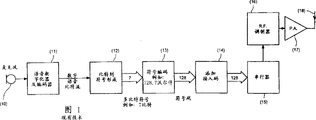
Fig. 1 illustrates the transmitter of the prior art of using with the present invention;
Fig. 2 illustrates an array antenna that uses with the present invention;
Fig. 3 illustrates the space/encode processor according to one embodiment of the invention;
Fig. 4 illustrates the path processing that is used for the time of advent and arrival direction combination according to one embodiment of the invention;
Fig. 5 illustrates the formation according to the Bulter matrix/Fourier conversion of the beam shaping of one embodiment of the invention.
Embodiment describes in detail
Fig. 1 has illustrated that the present invention designs the simplified block diagram of this type of mobile transmitter of decoding.The transmitter of the prior art of the same form that transmitter is within citing document to be announced.
Digitlization is from the voice signal of microphone 10 and use the above-mentioned voice signal from microphone 10 of speech coding algorithm compression within speech coder 11 so that produce the digital bit stream of representing voice signal.Existing Digital Cellular System is respectively the bit rate of Speech Signal Compression to 13KB/s (GSM) and 7KB/s (IS54), and under existing state of the art in addition employing also can keep acceptable voice quality to the speech coder that bit rate reduces to 3.6KB/s.
By using error correction coding can again improve bit rate from speech coder.Add most of redundant so that not only protect the most responsive significant bits but also the least responsive significant bits of can not encoding simultaneously.In any case, can think that this kind coding is the part of the square frame 11 within Fig. 1.Final encoded digital voice from square frame 11 are formed the symbol of many bits so that carry out spread spectrum coding within square frame Figure 13.For example, can form the piece of 7 bits, by each pattern of 128 7 possible bit modes of one of 128 orthogonal walsh-Hadamard (Walsh-Hadamard) numeral expression, therefore, the coefficient of spread spectrum bit rate increases to 128/7.When adopting this kind piece orthogonal spectrum expansion symbolic coding, the form of the preferred error correction coding within speech coder 11 is Read-Solomon (Reed-Solomon) coding, this coding many bit symbols that are suitable for encoding.Can adopt the whole bag of tricks to finish the combination of Read-Solomon (Reed-Solomon) coding and Walsh-Hadamard (Walsh-Hadamard) coding so that produce nonequilibrium coding for the most responsive and least responsive significant bit.For example, the Read-Solomon of being constructed within GF2**7 (Reed-Solomon) coding can be encoded the piece of one 7 bit important sign so that produce the RS-encoding block that comprises the greater number symbol." Jia Luohua (Galois) territory or GF " be whole from 0 to certain peaked integer set of asking closed set under the die combination computing at certain.GF2**7 (2 7 power or GF27) means whole from 0 to 127 integer, the binary system numeral of 7 promptly whole bits.If come in conjunction with in these above-mentioned numerals set both by another 7 bit value of 7 bit width XORs (XOR-mould 2 adds) within aggregated result, so therefore this to be integrated under the combinatorial operation " XOR " be " sealing ".Can form 7 bit blocks rather than RS coding to the least important sign of remainder.Encode 7 bit symbols to Walsh-Hadamard (Walsh-Hadamarm) encoder 13 from encoder 11 output RS codings and non-RS subsequently, in such cases, within encoder 11, finished the conversion 12 of bit to symbol, like this for the symbol situation of RS coding at least.
A kind of selectable non-equilibrium coding method is that significant bits is formed for example symbol of 5 bits, and RS encodes the symbol of above-mentioned 5 bits so that form 5 bit symbol pieces of bigger RS coding within GF2**5 subsequently.Add subsequently two least important bits to the RS symbol of each 5 bit so that obtain the symbol of 7 bits, the symbol of submitting above-mentioned 7 bits subsequently to Walsh-Hadamard (Walsh-Hadamard) encoder 13 so that obtain the numeral of 128 bits.
In order to provide confidentiality to separately dialogue, encryption can or be added within square frame Figure 11 or is added within square frame Figure 12, as the U.S. patent No.5 that quotes above in this literary composition as reference, described in 353,352.
Different travelling carriages is according to belonging to symbol encoder 13 generation Walsh-Hadamard (Walsh-Hadamard) numerals that 128 same numerals are gathered, help the difference between different mobile stations by this, inserting numeral at square frame Figure 14 place is the Modulo-two operation that combines with numeral by bit-wise, as U.S. patent No.5, described in 353,352.Preferably select to insert numeral like this, i.e. the coding of travelling carriage transmitter access numeral is different from whole 128 the possible codings that produced by any other travelling carriage transmitter maximumly and inserts numerals.
For the purpose of simplifying, among Fig. 1, omitted for using unessential details, add the source of voice messaging, encryption key to and the whole controls of processor controls for transmitter are not shown such as signaling information.
Insert the output that encoder 14 has produced 128 bits, these 128 bits if necessary are converted to serial flow by serializer 15 so so that the modulation wireless carrier frequency.Bit stream adds to modulator 16 so that produce modulated RF signal, within power amplifier 17, amplify subsequently above-mentioned modulated RF signal to transmitted power level so that use antenna 18 transmissions.For the purpose of simplifying, the corresponding mobile station receiver circuit that same antenna is used to receive is not shown.
Fig. 2 illustrated being connected to of cylindrical antenna array 21 institute of the present invention invention processor 60, and such as U.S. patent No.08/179, described in 953, this patent is quoted as reference above in this literary composition.
Arrange antenna element 22 according in line row 20, and arrange that these in line row 20 are around the cylinder 21 on the antenna mast at cell-site location place.So connect column unit so that form column signal 23, and the in line row of each this kind have shown and are vertically looking up the directivity within the plane and have wide beamwidth within level (azimuth) plane.Handle each column signal by the receive channel 31 that has constituted a channel bank 30.Each channel 31 comprises first RF filter 310 for example, low noise amplifier 311, second RF filter 312, the downconverter 313 that uses public local crystal oscillator 32, intermediate-frequency filter 314, IF amplifier 315 and produces the plural A/D converter 316 of expression from the plural numerical value sample stream of the RF signal of each in line column unit.
A/D converter can comprise use I, Q frequency mixer and I, the quadrature down-conversion device of the A/D converter of Q or selectively adopt the log-polar digitizing technique, this log-polar digitizing technique is quoted the U.S. patent No.08/179 as reference in view of the above in this literary composition, describe to some extent in 953.
Plural number numeral output 36 is fed to the processor 60 that comprises space/numeral processor 40 subsequently so that distinguish and export the isolated sign stream of being received from each travelling carriage transmitter (Fig. 1), and one separately the storehouse 50 of Traffic Channel processor unit handle each Traffic Channel symbols streams so that reproduce voice signal, signaling and control information or user data, such as fax or computer data signal.
Fig. 3 has illustrated the part of the space/numeral processor 40 that comprises the two Dimension Numerical Value conversion.(t1) signal of receiving from the set of antenna array forms beam shaping matrix for t1 to delegation's input signal simultaneously.At continuous t2 constantly, t3 ..., the set of aerial signal that t128 receives is fed to the same beam shaping matrix 70 of respective amount.What it will be appreciated that is to be plural numerical value by the handled whole signals of two-dimensional transform, and this plural number numerical value comprises real part and imaginary part, and each is expressed as fixed point or floating-point binary value.Generally speaking, fixed-point representation is more superior because require to handle fixed-point value hardware be not very expensive.
One group of output signal of beam shaping matrix computations, each output signal is corresponding to the directional antenna beam that has formed in the specific direction within the azimuth.Generally equal the quantity of antenna array for each number of beams of being calculated of sampling instant t (i), therefore, the beam shaping matrix multiply by the square formation of a plural beam shaping coefficient corresponding to delegation's input value.To this, at U.S. patent sequence number No.08/568,664, numerical value beam shaping and high-efficiency method have been described among being entitled as " high-performance device of implementing modulation and digital beam-forming when being used for aerial array ", this patent is incorporated by reference in this text photograph in view of the above in this literary composition.
By the beam shaping matrix, obtained enhancing with respect to the signal that arrives from other direction corresponding to the signal that arrives from specific direction of beam direction.Beam-shaper calculates the wave beam comprise all directions and has therefore strengthened whole signals within one or another wave beam.As discussed below, yet the unnecessary whole calculated signals wave beams to occurring simultaneously of beam-shaper are because it carries out meticulousr direction adjustment to each mobile station signal best.
For continuous moment t1, t2, the beam signal of t128 institute compute beam direction 1 forms 128 complex values input vectors fast Hadamard transform (FWT) processor 71 of wave beam 1, and similarly for continuous moment t1,, the set of 128 beam signals of t128 institute compute beam direction forms input vector the FWT processor 71 of wave beam N.Also carry out the FWT processor for other whole wave beams, produced the two-dimensional transform result's of a 128 * N array by this, first dimension of conversion is that the antenna-unit/wave beam-space and second dimension are time/numeral-spaces.Each FWT processor is transformed to 128 input values 128 output valves and uses parallel fully each FWT of logical construct so that computing very apace, as the U.S. patent No.5 that authorizes the applicant, 357,454 is described, and this patent is all quoted as reference in this literary composition in view of the above.
In Fig. 3,, suppose that the computing that the access numeral that uses assignment to give specific mobile station signal goes to disturb the set of 128 input values comprises as first step within FWT processor 71 for the purpose of simplifying.This step has been decomposed the corresponding scrambler 14 performed steps by Fig. 1.At first select to insert numeral so that the previous travelling carriage transmitter of receiving at the place, base station that peak signal recognized that uses is given in this numeral assignment.To cause one of correspondence of 128 FWT processor outputs from one of relevant FWT processor 71 of N wave beam of maximum output by the symbol that this transmitter sent.Wave beam among discussing should be unable to promptly change between a symbol (symbol time generally is millisecond (ms)/one) and another symbol, because the travelling carriage transmitter can be according to so huge angular speed around aerial array.Therefore, can predict according to previous result and to be about to be used to discern the wave beam that has sent symbol, and after the Symbol recognition that has sent, can check the value within the same symbol box within other wave beam so that determine whether this signal increases within another Direction box; In some aspects, if the travelling carriage transmitter moves, the signal within another wave beam/Direction box will become bigger so, and the wave beam that therefore will change this travelling carriage of decoding.In certain interstage, when travelling carriage across two wave beams and when producing similar results from two adjacent groups of 128 outputs in view of the above, the weighted sum of two groups of 128 outputs can be used to decipher this symbol.
Decipher a symbol comprise mention above the identification and the peaked coefficient of 128 values or the maximum coefficient of 128 FWT processors outputs of single wave beam.Use parallel fully logic can finish this point very apace, as at U.S. patent No.5, described in 187,675, this patent is incorporated by reference in this text photograph in view of the above in this literary composition.After recognizing peaked coefficient, this value is set within 128 value arrays of this wave beam (perhaps a plurality of wave beams are if sue for peace a more than wave beam) is zero being used to decipher.Therefore, export numerical value from 128 * 8 spaces/numeral thresholding of being calculated by space/numeral processor, it is zero that a value (two values of possibility) is set.Use the value of the opposite order inverse transformation remainder of Fig. 3 subsequently, promptly carry out contrary FWT for the value of row, use same access numeral again scrambling they, and multiply by capable value so that again obtain 128 * N value by the matrix inversion of beam shaping matrix subsequently in space/time-domain.
Because predicted previous this wave beam in advance according to the wave beam decoded signal, so what will appreciate that is that beam shaping matrix 70 does not need to calculate the beam signal for whole wave beams, and just receive the strong and the most possible wave beam compute beam signal that is positioned at one of both sides for prediction, so that monitor around signal to adjacent beams to moving string owing to transmitter.Therefore, unnecessary for unevaluated beam signal execution FWT processor 71.Yet, handle 70 in order to reverse beam shaping, the quantity of the output valve of calculating must equal the quantity of input value, promptly the beam shaping matrix must be square formation and so information can not lose.Yet possible is is contained in corresponding to many zero matrix reduction matrix multiplications within the compute beam row not by use, as long as matrix inversion still exists and comprise correct beam shaping coefficient corresponding to necessary wave beam is capable.Owing to will require subsequently to calculate in advance and store diverse matrix and contrary, so the efficient of preferably using single matrix and when calculating unwanted wave beam, not paying close attention to waste for each sense.If do not need corresponding signal of wave beam decoding, so still saved unwanted FWT.
Now, the signal of being received from different travelling carriage transmitters is unnecessary aims at its 128 sampling symbol periods exactly.In addition, performed signal sampling is unnecessary synchronous with center or optimum sampling point each symbol within A/D converter 316.Really, because well-known multipath transmisstion phenomenon causes receiving that the signal from any specific travelling carriage transmitter has had the time interference, received that herein each delayed version of this signal is referred to as " directly " from the signal reflex of the different delay with many sample period time-delays of possibility of high-lager building, hillside and the like object.The misalignment of sampling timing has also produced the separation in footpath, wherein because the misalignment of sampling timing has caused sampling to come across between two chips, because the separation in footpath has caused for two viewed correlations of chip offset across between the correct sampled point.Aforesaid list of references has explained that how to be offset the FWT of 128 sample value vectors in time by calculating handles these effects so that solve the time delay of certain echo.The signal that the FWT vector of each skew and the complex weighted Calais mutually that solves phase deviation and each path fading are obtained merging is so that decoding.Make and share complex weighted addition and select chip offset to be used for merging to be called " Rake (RAKE) tap ", and this coefficient is called " Rake (RAKE) coefficient ".The real part and the imaginary part that comprise 2 contrary time power by restriction Rake (RAKE) coefficient can be simplified the merging with complex weighted FWT, and this mergings is compared with the complex weighted accurately value of use and comprised acceptable loss.The binary value that bit serial provided of the multiplication time delays easy to implement of contrary time power by 2, as the U.S. patent No.5 that authorizes the applicant, 305,349 are entitled as described in " Rake (Rake) receiver with quantization parameter ", and this patent is incorporated by reference in this text photograph in view of the above in this literary composition.
Fig. 4 has illustrated and has been used for different chips displacements (Rake (RAKE) tap) and the device that how to omit two-dimensional transform that unwanted FWT implements in addition.Input block 72 receives from the A/D conversion sample stream of each antenna channel 31 and 128+L the memory cell that sample value is moved into each channel according to clock.Extra " L " unit is corresponding at the timing base of 128 chips of the Walsh of receiving recently (Walsh) numeral and expect the quantity of spread spectrum time the earliest between the person, it is expressed as chip period, spread spectrum or between two different mobile stations transmitters of base station different distance or between two different footpaths of propagating via the path of different length.Produce N wave beam value corresponding to being connected to the beam shaping matrix of a N input/N output from one of 128+L buffer memory sample value of N antenna channel and changing it.Await above-mentioned 128 selection subsequently from desired 128+L the value output that is positioned within the wave beam in certain path of certain signal corresponding to certain timing base of 128 chip Walsh numerals.Implement wave beam and the prediction regularly of certain path by channel tracker 73, channel tracker 73 is followed the tracks of maximal correlation at beam direction on any side of nominal arrival direction and is also had value with time migration correlation on side arbitrarily, i.e. a leading chip and a hysteresis chip of nominal anticipated time of advent.Channel tracker 73 also follow the tracks of from a Walsh-Hadamard (Walsh-Hadamard) symbol period to another cycle the average complex values of average maximal correlation, this has produced Rake (RAKE) the coefficient weighting that is used to merge different paths.Employing by the complex conjugate of channel tracker 73 desired value that produces for 128 Walsh (Walsh) frequency spectrum output of a weights of certain signal, and above-mentioned frequency spectrum output and for 128 weight vectors additions in whole other paths of same signal from each FWT.Each path have the timing of self and be positioned at other path of same signal within the different wave beam.Therefore, Rake (RAKE) merges and can for example merge one group from the signal that reflects than edifice or hillside from Walsh (Walsh) correlation of the direct path of receiving in the south and from north.Channel tracker determines which merges and for example above-mentioned above-mentioned these signals of invention Rake (RAKE) combiner merging that contain quantization parameter of channel tracker use mutually with the arrival direction which comprises maximum energy the time of advent.Because the complex conjugate weighting, the signal of merging should rotate the maximum that becomes number plane and determined 128 real parts in view of the above by maximum search circuit 74 to its end value.In Fig. 4, square frame Figure 74 also comprise to use by 128 Walsh (Walsh) spectrum in whole paths of channel tracker 73 weight coefficient that provides add up and.When having found maximum, its value is turned back to channel tracker so that upgrade the coefficient of next symbol period in time.It is with this path of use that channel tracker will also determine next time or whether another path has become to bigger.Self-evident ground, the circuit of Fig. 4 is also to reaching time and the now nonsensical direction calculating FWT that reaches, and therefore it weighted sum is not made contributions but calculate the above-mentioned time of advent and arrival direction so as to determine they one of when or whether become than preceding once to above-mentioned and contribution bigger, the greater will replace the smaller this moment.
Fig. 4 illustrated be used to select Rake (RAKE) tap or by buffering sample value L+1 to the 128+L annexation of the represented time of advent (i.e. the nearest possible time of advent).Show whole 128+L and be connected to the beam shaping matrix time of advent, although might reach the time (being that sample value 1 is to L) and omitted the beam shaping matrix for untapped.Only will carry out FWT to the output of 128+L from beam-shaper L+1.In such cases, expection has been received the path L+1 of the time of advent from direction " k ", therefore only is connected to 128 input FWT 71 from beam-shaper L+1 to the output of 128+L and exports so that produce one 128 Walsh (Walsh) frequency spectrum.Use has in square frame Figure 74 from the weight coefficient of channel tracker 73 within 128 boxes of Walsh (Walsh) frequency spectrum for other whole meaningful paths above-mentioned frequency spectrum output that adds up.When treated whole path, square frame Figure 74 determines maximum accumulated value and exports its coefficient as the symbol of having deciphered, and this value is turned back to channel tracker.Repeat subsequently corresponding to the two-dimensional transform sequence in each path so that the FWT value that regeneration adds up in the past, and after each FWT that regenerated, being provided with corresponding to the value of deciphering the symbol coefficient is zero, and the value of remainder is carried out against FWT.Subsequently to the beam shaping matrix inversion so that again the modification value is turned back to input block 72.Removed the signal of just having deciphered among the buffer value for whole meaningful paths (each is defined by the arrival direction and the time of advent) after, from then on this signal is removed in the situation and therefore can not disturbed the signal of having deciphered subsequently.
In the list of references of quoting, announcement from being to use barrel shifter corresponding to selected method for optimizing among the input block 72 of the specific time of advent.Barrel shifter be a kind of 128+L organize available tap select between on or the effective ways of one group of 128 tap of displacement down.Needed displacement " j " is expressed as binary integer between 0 to L:
j
0+2·j
1+4·j
2+8·j
3
As an example, maximum L is 15 herein.
The cylindrical shift unit of the first order is according to binary digit j
3Value be 0 or 1 to select 135 taps so that comprise or sample value 1 to 135 or sample value 9 to 143.135 selective value stand the selection of 131 values of another time subsequently, promptly according to j
2Value is 0 or 1 or selective value 1 to 131 or 5 to 135 last time.These 131 values are via the selection of 129 values again, promptly according to j subsequently
1Perhaps selective value 1 to 129 or 3 to 131 last time.At last, j
0Determined that last time the numerical value of selective value had selected 1 to 128 or 2 to 129.The advantage of this method is to compare with 128L time for L=128, and its sum of switching the position is approximately 2*128log
2(L), promptly switching of L limit for example, reduced approximate 2: 1 for its complexity of L=15, and more saved for bigger value L.
Therefore, described how to decipher and deduct first signal.After each iteration, insert the access numeral that numeral is the strongest mobile station signal of the next one for specific symbol of travelling carriage decoding and change subsequently, and carry out new iteration.After having deciphered each signal, preserve the maximum of this symbol of expression.Its complex values is the measurement of the phase place and the amplitude of this signal, and average complex values within as the described channel tracker of the list of references of quoting is so which plane the decision signal phase is positioned at, and the coherent detection that therefore can implement signal.The amplitude of pursuit gain also can be used for predicting the signal strength signal intensity order within 128 sample value mark spaces next time, therefore and implement the rearranging of processing sequence so that solves the difference decline of unlike signal, kept decoding in proper order like this according to the signal strength signal intensity of falling.
The index of the maximum FWT composition of having been discerned after having merged whole Rake (RAKE) tap provides the index that is set to zero FWT composition within the signal subtraction circulation.Therefore, Fig. 3 and 4 machine preferably include at least two separate phases:
Detection-phase: according to the past history that comprises very big energy, calculate FWT for the time of advent and arrival direction by channel tracker institute predicted path, by using the weight coefficient that channel tracker provided to be accumulated in 128 FWT within the box, determine the index of maximum accumulated value subsequently.
Subtract each other the stage: according to the reduction order of path intensity, recomputate same FWT as above-mentioned, and each composition with above-mentioned index was set is zero so that obtain being used for the path of the minimum path intensity of the next one is carried out the modification value of next two-dimensional transform before the signal of inverse two dimensional transform remainder.
In addition, can be called the three phases of " search phase " comprising:
Search phase: for another is not used in and detects and subtract each other time that reaches in stage or arrival direction and carry out two-dimensional transform so that detect the path of the following outstanding growth that is used to detect and subtracts each other at least.
In the list of references of being quoted, it may be needed also having instructed the four-stage that is called " orthogonalization again ", wherein via detecting, subtract each other and after the search phase having handled other signal, reuse the access numeral of signal last time and use an index of having determined to carry out new subtracting each other the stage for signal last time.In other words, omitted detection-phase, because known the index of current generation.Again the purpose in orthogonalization stage is to reduce the redundant error of being left over from signal subtraction stage last time, this error be since other signal exist cause subtracting each other error on the quantity.These error direct proportions are in the intensity of other signal, still with first signal correction.After having removed other signal that causes error and original formation in view of the above, can detect error by using FWT to carry out new being correlated with.The new stage of subtracting each other is removed error subsequently.
The preferred formula of beam shaping computing is described now.Incide the letter on the transmitted intensity array
 The vector V that number will cause antenna array signal 23:
A is the column vector of complex values a (i) herein.
The quantity of column signal depends on s and is a little arbitrarily to the size of antenna channel gain coefficient a (i) contribution, because its reason becomes fully aware of, so selects so that normalization a1 ..., the value of a (n):
|a1|
2+|a2|
2…+|a(n)
2|=1
Merge best from the energy of each unit so that produce the wave beam of the maximum directivity of signal-oriented source S in order to produce one, merge the complex conjugate that weight coefficient should equal a (i), promptly the signal of He Binging should be:
* represents that complex conjugate and # represent conjugate transpose herein.And this formula:
A #·
A=|a1|
2+|a2|
2+|a(n)|
2
It has been set has above equaled " 1 ".Therefore, the result is reduced to s, and it represents that s can equal whole signal energies of being intercepted and captured by array.
Therefore, the beam shaping matrix B must comprise one and equals A
#Row for use in the wave beam of required reception S.Yet, not definition of another row B, but having applied following extra requirement after, will become to so, promptly be provided with composition within the S wave beam be zero and multiply by B against after, signal S will disappear among whole antenna element values.
Therefore, the generation of multiplying each other of the vector V of receiving signal and beam shaping matrix B:
" s " is needed signal path and s1 herein, and s2 is corresponding to the mixed signal of other signal or other signal.
Being set to zero corresponding to the output of S is the same with deduct this vector from the result:
After multiply by B contrary, obtain subsequently:
B
-1·(B·
V)-S)=
V-B
-1·
S
It should equal zero, as long as B
-1S has eliminated composition S at whole places, unit.Therefore,
Perhaps
Row B corresponding to the wave beam of signal S has been described above
-1Equal coefficient vector a (i).
Because B*B
-1=I is the unit matrix by the N * N of contrary definition, and this is and row B=(a1
*, a2
*..., a (n) multiply by and equals | a1|
2+ | a2|
2+ ... + | a (n) |
2=1 row B is corresponding to, be given on the diagonal to be " 1 ", and other row of B multiply by contrary same row and necessarily obtains zero, because the off diagonal element of unit matrix I is zero.Therefore, whole other row of B necessarily are orthogonal to the B that value has constituted by a (i)
-1Row.By (r1, r2 ..., r (n)) and represent any other row of B, so must have:
r1.a1+r2.a2+r3.a3+…+r(n).a(n)=0
Also can at random require r1
2+ r2
2+ ... + r (n)
2=1.
Adopt a row that equals given vector to construct this kind matrix, other whole row is orthogonal to this row and any mould value quadratic sum that equals unit value is called orthogonal matrix, and it can implement structure by known Graham-Schmidt (Gram-Schmidt) orthogonalization method.When assigned value is gone to other, some degrees of freedom are arranged, and as explained above if desired, so in this manner so that maximization zero sum within matrix can be implemented this point.
Therefore, illustrated by delegation is set to equal to construct the beam shaping matrix that the N-1 that is constructed other by Graham-Schmidt (Gram-Schmidt) orthogonalization is capable in the conjugation of receiving signal gain and phase place at N antenna element row place.
Use boolean spy's (Bulter) matrix or its numerical value correspondent method (being discrete Fourier (Fourier) conversion) can obtain another formula of beam-shaper.One group is arranged in cylinder 21 signal from N element antenna unit 20 on every side according to equilateral form and is connected to boolean spy (Bulter) matrix 80.The output that boolean spy (Bulter) matrix 80 produces N figure signal, this output relates to N the input signal that is produced by the N with orthogonal property * N discrete Fourier (Fourier) transformation matrix.When signal incided on the array of THETA from the deflection that slowly changes, the signal form of receiving in the place, unit moved around array lentamente, and this pattern is identical with the form of being had only the 2Pi/N value that is shifted by a unit in advance.Boolean spy (Bulter) matrixing value becomes on amplitude and equals value at advance value THETA place, and THETA-2Pi/N also is same, although the phase shift variations of transformed value a plurality of 2Pi/N.In fact, almost identical in the extreme for the amplitude of whole THETA value transform values, although phase place has only changed a plurality of THETA.Therefore, by different gains or attenuation coefficient c1, c2, c (n) is added to and carries out the required weighting that the constant amplitude shaping can provide cell signal very exactly within the amplitude shaping unit 81, if for the conversion composition 1 to N is necessary, amplitude shaping unit 81 also can insert the variation of stationary phase so, although phase unit 82 the phase change of each conversion and amplitude shaping value a plurality of arrival directions angle THETA.
At last, if select phase unit 82 necessary phase place to be provided for the wave beam of N the while a plurality of 2Pi/N in interval, phase unit 82 is contrary boolean spy (Bulter) matrixes (the perhaps inverse Fourier transform within the numerical value territory) so.
In Fig. 5, the output of the input block having been transferred to boolean spy (Bulter) matrix unit 80 and amplitude reshaper 81 has been described.This is possible, because the function performed by boolean spy (Bulter) matrix unit 80 and amplitude reshaper 81 is neither relevant with arrival direction relevant with the time of advent again, and can carry out this function on the basis of each sample value, and the result is stored within the buffering area 72.Select 128 of 128+L unit of every N buffering area subsequently as above-described barrel shifter (not shown) so that form N the input to 128 phase unit 82, above-mentioned phase unit 82 is finished beam shaping for the path with the specific time of advent and arrival direction.In input and after subtracting each other, with regard to input block 72, only need the signal of inverse transformation remainder and do not need above-mentioned redundant signals contravariant is changed to not only via amplitude shaping unit 81 but also via boolean spy (Bulter) matrix 80.
The advantage of carrying out the fixedly conversion of boolean spy (Bulter) matrix 80 and amplitude shaping 81 before entering into input block shown in Figure 4 is that beam shaping elements 70 becomes the phase unit 82 that only changed the phase place of signal before merging them and not having weighted amplitude simply.In addition, use fast Fourier transform (FFT) can implement phase unit 82 effectively.FFT produces the wave beam have from the interval 2Pi/N of start angle THETA institute, wherein by the stationary phase slope is added to by following coefficient given input implement above-mentioned wave beam:
1,EXP(THETA),EXP(2*THETA),EXP(3*THETA),…
THETA is between 0 to Pi/N herein, perhaps-Pi/N and+Pi/N between.In the case, THETA represents the more accurate arrival direction resolution of precision less than 2Pi/N, although FFT is according to the step explanation wave beam of 2Pi/N.
Fig. 4 and Fig. 5 make up and have shown a fft processor and the cascade that works in the FWT processor of another dimension that works in the one dimension of two-dimensional array number.FWT and FFT all are the series that belongs to the Walsh Fourier transform, and their differences only are the step of its application, promptly well-known conduct " twiddle factor ".Fast Walsh-Fourier (Walsh-Fourier) conversion comprises the pectination that is used to be called " butterfly " level to value, above-mentioned level calculate be distributed at different levels and value and difference in case the rotation plural number with value and fixed amount of difference phase place, this fixed amount is called " twiddle factor ".Pure Fourier transform has twiddle factor between per two continuous butterfly levels, yet pure Fast W alsh-Fourier transform is without any the twiddle factor level.Mix Walsh-Fourier transform and have some twiddle factor levels; Two-dimension fourier transform is an example and has omitted a twiddle factor level.The Fourier transform that three-dimensional array is constituted be identical to being placed in the one dimensional fourier transform that whole numerical value within the big vector carry out computing, but two twiddle factor levels have been omitted, and so on, when carrying out M dimension Fourier transform, omit M-1 twiddle factor level.For the phase unit 82 of Fig. 5 and the FWT processor 71 of Fig. 4, can very carry out joint transform effectively by big one-dimensional transform that uses 128 whole * N numerical value to be arranged within the single vector, six twiddle factor levels have just been omitted corresponding to 128 FWT parts, this is equivalent to contain the 7 degree of freedom Fourier transform of two numerical value within every dimension, and has omitted another twiddle factor level corresponding to the two dimensional cascade of FFT and FWT part.
Row cite an actual example above-mentioned clearer with making: when whole arrays comprises many values that equals two power time, can construct fast Walsh-Fourier transform the most effectively.Therefore, if the quantity N of selection wave beam is two power, for example be N=32, because the big or small N=128 of FWT part has been two power, so the total quantity of numerical value will be 32 * 128 or 4096, this is 2
12
One 2
12FFT will generally include 12 butterfly levels of 11 twiddle factor levels that have between 12 butterfly levels.Yet in an application of the invention, desired conversion is 8 dimension conversion, i.e. 32 * 2 * 2 * 2 * 2 * 2 * 2 * 2=4096 values altogether of 8 dimension group numerical value of a following size.
Therefore, the quantity of twiddle factor level is reduced to 8-1=7, remaining in 11 four of having only that 4096 FWT can be provided.Remaining four corresponding to these parts between 32 FFT parts of the first five butterfly level.
Therefore, illustrated that above the vague generalization one-dimensional fast Walsh-Fourier transform that uses programming can carry out cascade at FFT beam-shaper within the data plane 82 and FWT decoder 71 within another datum plane so that eliminate suitable twiddle factor level.If construct this kind device fully, effectively and economically, omit not whole set that calculating with FWT or wave beam can become meaningless and calculate each path so and become simpler.
Another variation is to notice that the accurate beam direction for each path is that signal subtraction has relation with obtaining accurately, has formed above-mentioned accurate beam direction by the THETA value that each path is defined in independently among Fig. 5.Can carry out accurate input within detection-phase by only calculating the many groups wave beam that uses THETA-0, in such cases, have by chance at certain signal midway of the arrival direction between two wave beams and will occur within the wave beam of these two vicinities, this regards two paths as.Yet, as long as channel tracker 73 provides the suitable coefficient of two adjacent beams, the result that will correctly be detected so.Yet, subtract each other the stage and preferably use the right value of THETA so that this signal is come across within institute's compute beam unique, from wherein eliminating it.Can determine the THETA value that requires by channel tracker according to Rake (RAKE) coefficient of two adjacent beams being used to detect.
Also have other variation to comprise not to be to be provided be transformed into be divided into zero but at the channel tracker that upgrades detected value of symbol just so that after the next value of prediction, from before the execution inverse transformation be transformed into branch among deduct the predicted value of having upgraded.
Provide for a kind of variation or the another kind of whole labor of tow sides that changes and exceeded the scope that to use, the selection of above-mentioned two kinds of variations depends on the accurate parameter of certain enforcement, for example the enforcement of size, signal bandwidth, volume of business and the calculating of antenna columns, Walsh-Hadamard numeral be by programmable signal processor, hardware logic and or application-specific integrated circuit (ASIC) (ASIC) method, because the rapid progress aspect the silicon integrated technology, their ability day by day improve.
All are quoted this kind variation that the inventive principle of subtracting each other restituted signal within existing signal (perhaps numeral) space has living space dimension (perhaps antenna beam space) again implements by those skilled in the art and can think and all belong to as following claim within the described category of the present invention and spirit.
Claims (39)
1. communication system that comprises a plurality of travelling carriages and improve the base station, above-mentioned improvement base station are used to receive from the signal of above-mentioned travelling carriage and decipher the information carrying signal that above-mentioned travelling carriage sends, and above-mentioned communication system comprises:
Comprise the antenna assembly that is arranged in the antenna element around the supporting structure, this antenna assembly is used to receive the signal that sends from above-mentioned a plurality of travelling carriage and produces output signal from each antenna element;
Conversion equipment, this conversion equipment be used for to the signal from each above-mentioned antenna element amplify, filtering and be converted into the switching signal of respective amount so that handle;
Storage arrangement, this storage arrangement is used for temporarily storing the sampled value of many above-mentioned switching signals; And
Processing unit, this processing unit is used for handling iteratively and handles above-mentioned sampled value of having stored continuously again so that in turn decipher above-mentioned information from each above-mentioned travelling carriage, wherein from above-mentioned store sample value, discern the information symbol that sends by one of above-mentioned travelling carriage by the processing that above-mentioned processing unit provided, decipher above-mentioned information carrying signal by this and among the store sample value, deduct the value that depends on the above-mentioned symbol of identifying information, reduced the interference between signals that is about to decoding at the signal of just having deciphered with in iteration subsequently the time by this.
2. according to the communication system of claim 1, it is characterized in that wherein some above-mentioned travelling carriage side by side uses same wireless frequency channel to send above-mentioned information at least.
3. according to the communication system of claim 1, it is characterized in that wherein some above-mentioned travelling carriage sends code division multiple access (CDMA) signal at least.
4. according to the communication system of claim 1, it is characterized in that wherein above-mentioned processing unit comprises further:
Be used to merge the above-mentioned store sample value of several correspondences of changing from each antenna element so that strengthen device from certain direction received signal, wherein the one of specific of above-mentioned travelling carriage is positioned within above-mentioned certain direction.
5. according to the communication system of claim 1, it is characterized in that, wherein according to the above-mentioned signal of having deciphered continuously of selective sequential of receiving that signal strength signal intensity falls progressively.
6. according to the communication system of claim 4, it is characterized in that the said apparatus that wherein is used to merge calculates the weighted sum of a merging value, as the weighting of one group of plural number beam shaping coefficient.
7. according to the communication system of claim 6, it is characterized in that, wherein when each iteration, revise above-mentioned beam shaping coefficient so that the decoded signal when strengthening in this time iteration.
8. according to the communication system of claim 1, it is characterized in that wherein above-mentioned processing unit comprises:
Beam shaping device, this beam shaping device are used to merge that many groups are above-mentioned comprises by above-mentioned conversion equipment from the storage sample value of the same signal sample of constantly being changed of each antenna so that produce for the wave beam sample value of receiving signal from the pairing moment of a plurality of arrival directions.
9. communication system according to Claim 8 is characterized in that, comprises further:
CDMA despreading device, this despreading device are used for handling from above-mentioned a plurality of arrival directions one of same in the above-mentioned wave beam sample value of constantly being received continuously so that from one of above-mentioned travelling carriage sent and receive in place, above-mentioned improvement base station from above-mentioned arrival direction above-mentioned distinguished symbol.
10. according to the communication system of claim 9, it is characterized in that wherein above-mentioned CDMA despreading device comprises and calculate the Walsh-Hadamard transform so that obtain a plurality of Walsh spectrum components, each above-mentioned spectrum component is corresponding to one of permission alphabet of information symbol.
11. the communication system according to claim 10 is characterized in that, wherein by determine above-mentioned Walsh spectrum component and in view of the above among the above-mentioned permission alphabet of symbol the maximum of corresponding symbol recognize above-mentioned distinguished symbol.
12. the communication system according to claim 11 is characterized in that, wherein after decision the maximum, the Walsh spectrum component that above-mentioned maximum is set is zero.
13. the communication system according to claim 12 is characterized in that, is that the zero above-mentioned Walsh frequency spectrum of inverse transformation afterwards is so that the wave beam sample value that obtains revising at the composition that is provided with above-mentioned maximum wherein.
14. communication system according to claim 13, it is characterized in that, wherein use head sea beam shaping device to merge the wave beam sample value of above-mentioned modification so that the storage sample value that obtains revising, the storage sample value of above-mentioned modification is being carried out iteration subsequently so that decoding substitutes the one of original of above-mentioned storage sample value before from the symbol of different mobile stations transmitter.
15. one kind comprises a plurality of travelling carriages and improves the communication system of base station, above-mentioned improvement base station is used to receive the alphabetic(al) information symbol of permission that signal that above-mentioned travelling carriage sent by means of the access numeral of assignment and decoding belong to coded identification within above-mentioned transmission, and above-mentioned communication system comprises:
Comprise the antenna assembly that is arranged in the antenna element around the supporting structure, this antenna assembly is used to receive the signal that sends from above-mentioned a plurality of travelling carriage and produces output signal from each antenna element;
Conversion equipment, this conversion equipment be used for to the signal from each above-mentioned antenna element amplify, filtering and be converted into the switching signal of respective amount so that handle;
Storage arrangement, this storage arrangement are used for temporarily storing many sampled values of the above-mentioned signal of changing successively from each above-mentioned antenna element; And
The two Dimension Numerical Value converting means, this two Dimension Numerical Value converting means is used to handle above-mentioned use assignment and gives the storage sample value of one of access numeral of first above-mentioned travelling carriage so that produce the two-dimensional array of conversion sample value, being positioned at may arrival direction along the above-mentioned conversion sample value of the one dimension of the above-mentioned two-dimensional array difference when arriving base station by above-mentioned first travelling carriage signal transmitted, is positioned at along the above-mentioned conversion sample value of another dimension of above-mentioned two-dimensional array corresponding to one of different relevant with above-mentioned information symbol within the permission alphabet of symbol
16. the communication system according to claim 15 is characterized in that, wherein selects employed access numeral to be meant and joins this receives the travelling carriage with maximum signal at place, above-mentioned base station this kind access numeral.
17. communication system according to claim 15, it is characterized in that, wherein the above-mentioned decoding of one of above-mentioned information symbol comprises the maximum that determines above-mentioned conversion sample value and discerns a symbol that reaches direction that belongs to the above-mentioned permission alphabet of symbol and also have this signal by this, and wherein above-mentioned signal code is decoded.
18. communication system according to claim 15, it is characterized in that wherein the above-mentioned decoding of one of above-mentioned information symbol comprises and using a combination and coefficient to merge to be adjacent to along the above-mentioned conversion sample value of arrival direction dimension so that produce a merging value for each position within another dimension of the bidimensional array of above-mentioned conversion sample value.
19. the communication system according to claim 18 is characterized in that, comprises further:
Determine the maximum of above-mentioned merging value and discern the above-mentioned information symbol of having deciphered by this.
20. the communication system according to claim 17 is characterized in that, wherein after having discerned above-mentioned symbol, the maximum that above-mentioned conversion sample value is set is zero.
21. the communication system according to claim 20 is characterized in that, comprises further:
Inverse two dimensional transform device, this inverse two dimensional transform device are used for conversion and contain one and be set to zero above-mentioned conversion sample value so that obtain being stored in modification storage sample value within the above-mentioned storage arrangement.
22. the communication system according to claim 21 is characterized in that, comprises further:
Use has assignment and handles the storage sample value of above-mentioned modification and discern a device by above-mentioned second symbol that travelling carriage sends by this for the above-mentioned two-dimensional transform device of the access numeral of second travelling carriage.
23. communication system according to claim 22, it is characterized in that, wherein after having discerned by above-mentioned second symbol that travelling carriage sent, be provided with corresponding being transformed into be divided into zero and complete above-mentioned inverse two dimensional transform so that produce the storage sample value of another modification.
24. communication system according to claim 23, it is characterized in that, wherein use the access numeral of selecting continuously handle iteratively above-mentioned another revise sample value in case discern continuously from the symbol that travelling carriage sent of the above-mentioned access numeral of assignment and having discerned each symbol after by be provided with transformed value be zero and the execution inversion bring and revise above-mentioned storage sample value further.
25. the communication system according to claim 24 is characterized in that, wherein according to the signal strength signal intensity order that falls progressively continuously, the travelling carriage that receives at place, above-mentioned base station given in the access numeral of the above-mentioned Continuous Selection of assignment.
26. one kind comprises a plurality of travelling carriages and improves the communication system of base station, above-mentioned improvement base station is used to receive the alphabetic(al) information symbol of permission that signal that above-mentioned travelling carriage sent by means of the access numeral of assignment and decoding belong to coded identification within above-mentioned transmission, and above-mentioned communication system comprises:
Comprise the antenna assembly that is arranged in the antenna element around the supporting structure, this antenna assembly is used to receive the signal that sends from above-mentioned a plurality of travelling carriage and produces output signal from each antenna element;
Conversion equipment, this conversion equipment be used for to the signal from each above-mentioned antenna element amplify, filtering and be converted into the switching signal of respective amount so that handle;
Storage arrangement, this storage arrangement are used for temporarily storing the many sampled values from the continuous above-mentioned signal of constantly being changed of each above-mentioned antenna element; And
The two Dimension Numerical Value converting means, this two Dimension Numerical Value converting means is used to handle above-mentioned use assignment and gives the storage sample value of one of access numeral of first above-mentioned travelling carriage so that produce the two-dimensional array of conversion sample value, be positioned at above-mentioned conversion sample value along the one dimension of above-mentioned two-dimensional array corresponding to the different possible arrival direction by above-mentioned first travelling carriage signal transmitted, be correlated with corresponding to using to be offset within the permission alphabet at symbol a plurality of sample values and the one of different of above-mentioned information symbol in the stipulated time between relevant sample value and the above-mentioned information symbol along the above-mentioned conversion sample value of another dimension of above-mentioned two-dimensional array at place, above-mentioned base station; And
Be used for many above-mentioned corresponding to the device that repeats above-mentioned two-dimensional transform from the time migration that receives corresponding to signal lag by above-mentioned first travelling carriage of the time-delay echo of the caused above-mentioned signal of the institute's reflected signal of the object within propagation path.
27. the communication system according to claim 26 is characterized in that, comprises further:
Corresponding time of advent of the echo of prediction arrival direction and each above-mentioned very big intensity and revise above-mentioned echo reaches direction to the above-mentioned possible difference of being supposed by above-mentioned two Dimension Numerical Value converting means and the above-mentioned stipulated time skew that is used to be correlated with device.
28. the communication system according to claim 27 is characterized in that, comprises further:
Merge device, this mergings device use one group of weight coefficient merging corresponding to the direction of above-mentioned prediction and the conversion composition of the time of advent in case obtain one group corresponding to the relevant merging value of each symbol within the above-mentioned permission alphabet of symbol.
29. the communication system according to claim 28 is characterized in that, wherein decision has one of the above-mentioned merging value of amplitude peak and discerns one by this by symbol that above-mentioned first travelling carriage sent.
30. the communication system according to claim 29 is characterized in that, comprises further:
Be used to be provided with corresponding to the above-mentioned symbol of having discerned with corresponding to the two-dimensional transform composition of above-mentioned prediction direction and be two zero and be that the zero back above-mentioned conversion composition of inverse transformation is so that the device of the storage sample value that obtains revising at the composition that above-mentioned symbol, time and direction correspondence are set.
31. the communication system according to claim 30 is characterized in that, comprises further:
The access numeral that is used to use Continuous Selection handle the storage sample value of above-mentioned modification iteratively again in case in turn discern one by assignment select to insert the symbol that travelling carriage sent of numeral and the device of the storage sample value of another modification that generation is used to handle among next iteration after each iteration.
32. the communication system according to claim 31 is characterized in that, wherein inserts numeral according to assignment and yields and pledge allegiance to preface and select above-mentioned access numeral for the of the signal strength signal intensity of receiving of corresponding travelling carriage.
33. method that is used within communication system, receiving from many travelling carriage signal transmitteds, above-mentioned communication system comprises above-mentioned travelling carriage and improves the base station, each improves base station and is used to receive signal and decoding from above-mentioned travelling carriage belong to the symbol of encoding within above-mentioned transmission the alphabetic(al) information symbol of permission, the step that this method comprises:
Receive at antenna assembly place from signal that above-mentioned a plurality of travelling carriage sent and from each antenna element and produce output signal with the antenna element around the supporting structure of being arranged in;
For the signal from each above-mentioned antenna element amplify, filtering and be converted into the switching signal of respective amount so that handle;
Temporarily store many sampled values of the above-mentioned signal of being changed successively from each above-mentioned antenna element;
Handling above-mentioned use assignment gives the storage sample value of one of access numeral of first above-mentioned travelling carriage so that produce the two-dimensional array of conversion sample value, be positioned at above-mentioned conversion sample value along the one dimension of above-mentioned two-dimensional array corresponding to the different possible arrival direction by above-mentioned first travelling carriage signal transmitted, be correlated with corresponding to using to be offset within the permission alphabet at symbol a plurality of sample values and the one of different of above-mentioned information symbol in the stipulated time between relevant sample value and the above-mentioned information symbol along the above-mentioned conversion sample value of another dimension of above-mentioned two-dimensional array at place, above-mentioned base station; And
To many above-mentioned corresponding to repeating above-mentioned two-dimensional transform from the time migration that receives corresponding to signal lag by above-mentioned first travelling carriage of the time-delay echo of the caused above-mentioned signal of signal that object reflected within propagation path.
34. the method according to claim 33 is characterized in that, comprises step further:
Predict each very big intensity above-mentioned echo arrival direction and corresponding time of advent and revise above-mentioned echo to the above-mentioned possible different arrival direction of being supposed by above-mentioned two Dimension Numerical Value converting means and the above-mentioned stipulated time skew that is used to be correlated with.
35. the method according to claim 34 is characterized in that, comprises step further:
Use one group of weight coefficient to merge corresponding to the composition of conversion of the above-mentioned prediction direction and the time of advent so as to obtain one group corresponding to the relevant merging value of each symbol within the above-mentioned permission alphabet of symbol.
36. the method according to claim 35 is characterized in that, wherein decision has one of the above-mentioned merging value of amplitude peak and discerns one by this by symbol that above-mentioned first travelling carriage sent.
37. the method according to claim 36 is characterized in that, comprises step further:
Setting is two zero and is that the zero back above-mentioned conversion composition of inverse transformation is so that the storage sample value that obtains revising at the composition that above-mentioned symbol, time and direction correspondence are set corresponding to the above-mentioned symbol of having discerned with corresponding to the two-dimensional transform composition of above-mentioned prediction direction.
38. the method according to claim 37 is characterized in that, comprises step further:
The access numeral that uses Continuous Selection handle the storage sample value of above-mentioned modification iteratively again in case in turn discern one by assignment select to insert the symbol that travelling carriage sent of numeral and the storage sample value of another modification that generation is used to handle among next iteration after each iteration
39. the method according to claim 38 is characterized in that, wherein inserts the above-mentioned access numeral of the selective sequential of falling progressively that corresponding travelling carriage received signal intensity given in numeral according to assignment.
Applications Claiming Priority (2)
| Application Number | Priority Date | Filing Date | Title |
|---|---|---|---|
| US08/706,493 US5831977A (en) | 1996-09-04 | 1996-09-04 | Subtractive CDMA system with simultaneous subtraction in code space and direction-of-arrival space |
| US08/706,493 | 1996-09-04 |
Publications (1)
| Publication Number | Publication Date |
|---|---|
| CN1235720A true CN1235720A (en) | 1999-11-17 |
Family
ID=24837845
Family Applications (1)
| Application Number | Title | Priority Date | Filing Date |
|---|---|---|---|
| CN97199287A Pending CN1235720A (en) | 1996-09-04 | 1997-08-12 | Combined substractive interference cancellation and space diversity signal processing in cellular CDMA communication system |
Country Status (11)
| Country | Link |
|---|---|
| US (1) | US5831977A (en) |
| EP (1) | EP0923817B1 (en) |
| JP (1) | JP2001501390A (en) |
| KR (1) | KR20000068464A (en) |
| CN (1) | CN1235720A (en) |
| AU (1) | AU722689B2 (en) |
| CA (1) | CA2264860A1 (en) |
| DE (1) | DE69712347T2 (en) |
| ID (1) | ID17335A (en) |
| TW (1) | TW456120B (en) |
| WO (1) | WO1998010537A1 (en) |
Cited By (43)
| Publication number | Priority date | Publication date | Assignee | Title |
|---|---|---|---|---|
| CN103018558A (en) * | 2012-11-30 | 2013-04-03 | 合肥工业大学 | Master-slave multiprocessor real-time signal analyzing method |
| CN104662855A (en) * | 2012-06-25 | 2015-05-27 | 科希尔技术股份有限公司 | Modulation and equalization in an orthonormal time-frequency shifting communications system |
| US10158394B2 (en) | 2015-05-11 | 2018-12-18 | Cohere Technologies, Inc. | Systems and methods for symplectic orthogonal time frequency shifting modulation and transmission of data |
| US10334457B2 (en) | 2010-05-28 | 2019-06-25 | Cohere Technologies, Inc. | OTFS methods of data channel characterization and uses thereof |
| US10356632B2 (en) | 2017-01-27 | 2019-07-16 | Cohere Technologies, Inc. | Variable beamwidth multiband antenna |
| US10355887B2 (en) | 2016-04-01 | 2019-07-16 | Cohere Technologies, Inc. | Iterative two dimensional equalization of orthogonal time frequency space modulated signals |
| US10541734B2 (en) | 2016-04-01 | 2020-01-21 | Cohere Technologies, Inc. | Tomlinson-Harashima precoding in an OTFS communication system |
| US10555281B2 (en) | 2016-03-31 | 2020-02-04 | Cohere Technologies, Inc. | Wireless telecommunications system for high-mobility applications |
| US10568143B2 (en) | 2017-03-28 | 2020-02-18 | Cohere Technologies, Inc. | Windowed sequence for random access method and apparatus |
| US10567125B2 (en) | 2010-05-28 | 2020-02-18 | Cohere Technologies, Inc. | Modulation and equalization in an orthonormal time-frequency shifting communications system |
| US10666314B2 (en) | 2016-02-25 | 2020-05-26 | Cohere Technologies, Inc. | Reference signal packing for wireless communications |
| US10666479B2 (en) | 2015-12-09 | 2020-05-26 | Cohere Technologies, Inc. | Pilot packing using complex orthogonal functions |
| US10667148B1 (en) | 2010-05-28 | 2020-05-26 | Cohere Technologies, Inc. | Methods of operating and implementing wireless communications systems |
| US10681568B1 (en) | 2010-05-28 | 2020-06-09 | Cohere Technologies, Inc. | Methods of data channel characterization and uses thereof |
| US10693692B2 (en) | 2016-03-23 | 2020-06-23 | Cohere Technologies, Inc. | Receiver-side processing of orthogonal time frequency space modulated signals |
| US10693581B2 (en) | 2015-07-12 | 2020-06-23 | Cohere Technologies, Inc. | Orthogonal time frequency space modulation over a plurality of narrow band subcarriers |
| US10749651B2 (en) | 2016-03-31 | 2020-08-18 | Cohere Technologies, Inc. | Channel acquistion using orthogonal time frequency space modulated pilot signal |
| US10826728B2 (en) | 2016-08-12 | 2020-11-03 | Cohere Technologies, Inc. | Localized equalization for channels with intercarrier interference |
| US10855425B2 (en) | 2017-01-09 | 2020-12-01 | Cohere Technologies, Inc. | Pilot scrambling for channel estimation |
| US10873418B2 (en) | 2016-08-12 | 2020-12-22 | Cohere Technologies, Inc. | Iterative multi-level equalization and decoding |
| US10917204B2 (en) | 2016-08-12 | 2021-02-09 | Cohere Technologies, Inc. | Multi-user multiplexing of orthogonal time frequency space signals |
| US10938613B2 (en) | 2015-06-27 | 2021-03-02 | Cohere Technologies, Inc. | Orthogonal time frequency space communication system compatible with OFDM |
| US10938602B2 (en) | 2016-05-20 | 2021-03-02 | Cohere Technologies, Inc. | Iterative channel estimation and equalization with superimposed reference signals |
| US10951454B2 (en) | 2017-11-01 | 2021-03-16 | Cohere Technologies, Inc. | Precoding in wireless systems using orthogonal time frequency space multiplexing |
| US10965348B2 (en) | 2016-09-30 | 2021-03-30 | Cohere Technologies, Inc. | Uplink user resource allocation for orthogonal time frequency space modulation |
| US11025377B2 (en) | 2016-12-05 | 2021-06-01 | Cohere Technologies, Inc. | Fixed wireless access using orthogonal time frequency space modulation |
| US11038733B2 (en) | 2015-11-18 | 2021-06-15 | Cohere Technologies, Inc. | Orthogonal time frequency space modulation techniques |
| US11063804B2 (en) | 2017-04-24 | 2021-07-13 | Cohere Technologies, Inc. | Digital communication using lattice division multiplexing |
| US11070329B2 (en) | 2015-09-07 | 2021-07-20 | Cohere Technologies, Inc. | Multiple access using orthogonal time frequency space modulation |
| US11102034B2 (en) | 2017-09-06 | 2021-08-24 | Cohere Technologies, Inc. | Lattice reduction in orthogonal time frequency space modulation |
| US11114768B2 (en) | 2017-04-24 | 2021-09-07 | Cohere Technologies, Inc. | Multibeam antenna designs and operation |
| US11147087B2 (en) | 2017-04-21 | 2021-10-12 | Cohere Technologies, Inc. | Communication techniques using quasi-static properties of wireless channels |
| US11152957B2 (en) | 2017-09-29 | 2021-10-19 | Cohere Technologies, Inc. | Forward error correction using non-binary low density parity check codes |
| US11184122B2 (en) | 2017-12-04 | 2021-11-23 | Cohere Technologies, Inc. | Implementation of orthogonal time frequency space modulation for wireless communications |
| US11190308B2 (en) | 2017-09-15 | 2021-11-30 | Cohere Technologies, Inc. | Achieving synchronization in an orthogonal time frequency space signal receiver |
| US11190379B2 (en) | 2017-07-12 | 2021-11-30 | Cohere Technologies, Inc. | Data modulation schemes based on the Zak transform |
| US11283561B2 (en) | 2017-09-11 | 2022-03-22 | Cohere Technologies, Inc. | Wireless local area networks using orthogonal time frequency space modulation |
| US11310000B2 (en) | 2016-09-29 | 2022-04-19 | Cohere Technologies, Inc. | Transport block segmentation for multi-level codes |
| US11324008B2 (en) | 2017-08-14 | 2022-05-03 | Cohere Technologies, Inc. | Transmission resource allocation by splitting physical resource blocks |
| US11532891B2 (en) | 2017-09-20 | 2022-12-20 | Cohere Technologies, Inc. | Low cost electromagnetic feed network |
| US11546068B2 (en) | 2017-08-11 | 2023-01-03 | Cohere Technologies, Inc. | Ray tracing technique for wireless channel measurements |
| US11632270B2 (en) | 2018-02-08 | 2023-04-18 | Cohere Technologies, Inc. | Aspects of channel estimation for orthogonal time frequency space modulation for wireless communications |
| US11817987B2 (en) | 2017-04-11 | 2023-11-14 | Cohere Technologies, Inc. | Digital communication using dispersed orthogonal time frequency space modulated signals |
Families Citing this family (83)
| Publication number | Priority date | Publication date | Assignee | Title |
|---|---|---|---|---|
| US9134398B2 (en) | 1996-09-09 | 2015-09-15 | Tracbeam Llc | Wireless location using network centric location estimators |
| US7714778B2 (en) | 1997-08-20 | 2010-05-11 | Tracbeam Llc | Wireless location gateway and applications therefor |
| CA2265875C (en) | 1996-09-09 | 2007-01-16 | Dennis Jay Dupray | Location of a mobile station |
| US6236365B1 (en) | 1996-09-09 | 2001-05-22 | Tracbeam, Llc | Location of a mobile station using a plurality of commercial wireless infrastructures |
| US7903029B2 (en) | 1996-09-09 | 2011-03-08 | Tracbeam Llc | Wireless location routing applications and architecture therefor |
| US6016124A (en) * | 1997-04-07 | 2000-01-18 | Nortel Networks Corporation | Digital beamforming in a satellite communication system |
| US6600447B1 (en) * | 1997-12-19 | 2003-07-29 | Ericsson Inc. | Apparatus and method for determining signal direction from an estimated signal medium response for a ray component of a radio signal |
| KR100259051B1 (en) | 1997-12-31 | 2000-06-15 | 윤종용 | Apparatus and method of oqpsk in ds-cdma system |
| US7430257B1 (en) * | 1998-02-12 | 2008-09-30 | Lot 41 Acquisition Foundation, Llc | Multicarrier sub-layer for direct sequence channel and multiple-access coding |
| US5955992A (en) * | 1998-02-12 | 1999-09-21 | Shattil; Steve J. | Frequency-shifted feedback cavity used as a phased array antenna controller and carrier interference multiple access spread-spectrum transmitter |
| US6317466B1 (en) | 1998-04-15 | 2001-11-13 | Lucent Technologies Inc. | Wireless communications system having a space-time architecture employing multi-element antennas at both the transmitter and receiver |
| US6542484B1 (en) * | 1998-05-15 | 2003-04-01 | Telefonaktiebolaget Lm Ericsson (Publ) | Code allocation for radiocommunication systems |
| CN1059998C (en) * | 1998-06-22 | 2000-12-27 | 东南大学 | Multi-stage iteration multi-subscriber test method |
| US6307882B1 (en) * | 1998-07-10 | 2001-10-23 | Lucent Technologies Inc. | Determining channel characteristics in a space-time architecture wireless communication system having multi-element antennas |
| US8135413B2 (en) | 1998-11-24 | 2012-03-13 | Tracbeam Llc | Platform and applications for wireless location and other complex services |
| US7952511B1 (en) | 1999-04-07 | 2011-05-31 | Geer James L | Method and apparatus for the detection of objects using electromagnetic wave attenuation patterns |
| US7035238B1 (en) * | 1999-06-04 | 2006-04-25 | Lucent Technologies Inc. | Code assignment in a CDMA wireless system |
| EP1286735A1 (en) | 1999-09-24 | 2003-03-05 | Dennis Jay Dupray | Geographically constrained network services |
| US10684350B2 (en) | 2000-06-02 | 2020-06-16 | Tracbeam Llc | Services and applications for a communications network |
| US9875492B2 (en) | 2001-05-22 | 2018-01-23 | Dennis J. Dupray | Real estate transaction system |
| US10641861B2 (en) | 2000-06-02 | 2020-05-05 | Dennis J. Dupray | Services and applications for a communications network |
| CN1454404A (en) * | 2000-09-02 | 2003-11-05 | 诺基亚公司 | Fixed beam antenna array, base station and method for transmitting signals via a fixed beam antenna array |
| FI113590B (en) * | 2000-09-13 | 2004-05-14 | Nokia Corp | A method for forming directional antenna beams and a radio transmitter implementing the method |
| US6934317B1 (en) | 2000-10-11 | 2005-08-23 | Ericsson Inc. | Systems and methods for communicating spread spectrum signals using variable signal constellations |
| US8670390B2 (en) | 2000-11-22 | 2014-03-11 | Genghiscomm Holdings, LLC | Cooperative beam-forming in wireless networks |
| US7027489B2 (en) * | 2001-04-06 | 2006-04-11 | Interdigital Technology Corporation | Iterative fast fourier transform error correction |
| US9893774B2 (en) | 2001-04-26 | 2018-02-13 | Genghiscomm Holdings, LLC | Cloud radio access network |
| US10931338B2 (en) | 2001-04-26 | 2021-02-23 | Genghiscomm Holdings, LLC | Coordinated multipoint systems |
| US10355720B2 (en) | 2001-04-26 | 2019-07-16 | Genghiscomm Holdings, LLC | Distributed software-defined radio |
| US9819449B2 (en) | 2002-05-14 | 2017-11-14 | Genghiscomm Holdings, LLC | Cooperative subspace demultiplexing in content delivery networks |
| US10425135B2 (en) | 2001-04-26 | 2019-09-24 | Genghiscomm Holdings, LLC | Coordinated multipoint systems |
| US7136418B2 (en) * | 2001-05-03 | 2006-11-14 | University Of Washington | Scalable and perceptually ranked signal coding and decoding |
| US8082096B2 (en) * | 2001-05-22 | 2011-12-20 | Tracbeam Llc | Wireless location routing applications and architecture therefor |
| JP3469567B2 (en) * | 2001-09-03 | 2003-11-25 | 三菱電機株式会社 | Acoustic encoding device, acoustic decoding device, acoustic encoding method, and acoustic decoding method |
| JP3948249B2 (en) * | 2001-10-30 | 2007-07-25 | 日本電気株式会社 | Similarity determination apparatus, similarity determination method, and program |
| US6980614B2 (en) * | 2002-01-14 | 2005-12-27 | Raytheon Company | System and method for subband beamforming using adaptive weight normalization |
| JP4368575B2 (en) | 2002-04-19 | 2009-11-18 | パナソニック株式会社 | Variable length decoding method, variable length decoding apparatus and program |
| US10644916B1 (en) | 2002-05-14 | 2020-05-05 | Genghiscomm Holdings, LLC | Spreading and precoding in OFDM |
| US10142082B1 (en) | 2002-05-14 | 2018-11-27 | Genghiscomm Holdings, LLC | Pre-coding in OFDM |
| US9628231B2 (en) | 2002-05-14 | 2017-04-18 | Genghiscomm Holdings, LLC | Spreading and precoding in OFDM |
| US10200227B2 (en) | 2002-05-14 | 2019-02-05 | Genghiscomm Holdings, LLC | Pre-coding in multi-user MIMO |
| US7826870B2 (en) * | 2003-04-22 | 2010-11-02 | Raytheon Company | Separating mixed signals in a cellular environment |
| US7324582B2 (en) * | 2004-01-07 | 2008-01-29 | General Dynamics C4 Systems, Inc. | System and method for the directional reception and despreading of direct-sequence spread-spectrum signals |
| US8077691B2 (en) | 2004-03-05 | 2011-12-13 | Qualcomm Incorporated | Pilot transmission and channel estimation for MISO and MIMO receivers in a multi-antenna system |
| US11431386B1 (en) | 2004-08-02 | 2022-08-30 | Genghiscomm Holdings, LLC | Transmit pre-coding |
| US11184037B1 (en) | 2004-08-02 | 2021-11-23 | Genghiscomm Holdings, LLC | Demodulating and decoding carrier interferometry signals |
| US11552737B1 (en) | 2004-08-02 | 2023-01-10 | Genghiscomm Holdings, LLC | Cooperative MIMO |
| US7623599B2 (en) * | 2005-11-21 | 2009-11-24 | Freescale Semiconductor, Inc. | Blind bandwidth detection for a sample stream |
| US7480346B2 (en) * | 2006-09-13 | 2009-01-20 | Motorola, Inc. | Method and apparatus for improving sector to sector isolation in a Fourier transform matrix system |
| JP5003147B2 (en) * | 2006-12-26 | 2012-08-15 | ソニー株式会社 | Signal processing apparatus, signal processing method, and program |
| US8437431B1 (en) * | 2007-09-20 | 2013-05-07 | Gregory Hubert Piesinger | Sequential decoder fast incorrect path elimination method and apparatus for pseudo-orthogonal coding |
| US8497743B2 (en) * | 2007-12-24 | 2013-07-30 | Telefonaktiebolaget L M Ericsson (Publ) | Passive fourier transform circuits and butler matrices |
| WO2011103918A1 (en) * | 2010-02-25 | 2011-09-01 | Telefonaktiebolaget L M Ericsson (Publ) | A communication system node comprising a transformation matrix |
| US9130638B2 (en) | 2011-05-26 | 2015-09-08 | Cohere Technologies, Inc. | Modulation and equalization in an orthonormal time-frequency shifting communications system |
| US9071285B2 (en) | 2011-05-26 | 2015-06-30 | Cohere Technologies, Inc. | Modulation and equalization in an orthonormal time-frequency shifting communications system |
| US8976851B2 (en) | 2011-05-26 | 2015-03-10 | Cohere Technologies, Inc. | Modulation and equalization in an orthonormal time-frequency shifting communications system |
| US11943089B2 (en) | 2010-05-28 | 2024-03-26 | Cohere Technologies, Inc. | Modulation and equalization in an orthonormal time-shifting communications system |
| US9538493B2 (en) | 2010-08-23 | 2017-01-03 | Finetrak, Llc | Locating a mobile station and applications therefor |
| US8755636B2 (en) * | 2011-09-14 | 2014-06-17 | Mediatek Inc. | Method and apparatus of high-resolution image reconstruction based on multi-frame low-resolution images |
| US8811453B2 (en) * | 2011-09-22 | 2014-08-19 | Ericsson Modems Sa | Dynamic power scaling of an intermediate symbol buffer associated with covariance computations |
| US10003487B2 (en) | 2013-03-15 | 2018-06-19 | Cohere Technologies, Inc. | Symplectic orthogonal time frequency space modulation system |
| US9967758B2 (en) | 2012-06-25 | 2018-05-08 | Cohere Technologies, Inc. | Multiple access in an orthogonal time frequency space communication system |
| US10090972B2 (en) | 2012-06-25 | 2018-10-02 | Cohere Technologies, Inc. | System and method for two-dimensional equalization in an orthogonal time frequency space communication system |
| US10469215B2 (en) | 2012-06-25 | 2019-11-05 | Cohere Technologies, Inc. | Orthogonal time frequency space modulation system for the Internet of Things |
| US9912507B2 (en) | 2012-06-25 | 2018-03-06 | Cohere Technologies, Inc. | Orthogonal time frequency space communication system compatible with OFDM |
| US10411843B2 (en) | 2012-06-25 | 2019-09-10 | Cohere Technologies, Inc. | Orthogonal time frequency space communication system compatible with OFDM |
| US9929783B2 (en) | 2012-06-25 | 2018-03-27 | Cohere Technologies, Inc. | Orthogonal time frequency space modulation system |
| US10090973B2 (en) | 2015-05-11 | 2018-10-02 | Cohere Technologies, Inc. | Multiple access in an orthogonal time frequency space communication system |
| US10574317B2 (en) | 2015-06-18 | 2020-02-25 | Cohere Technologies, Inc. | System and method for providing wireless communication services using configurable broadband infrastructure shared among multiple network operators |
| US9866363B2 (en) | 2015-06-18 | 2018-01-09 | Cohere Technologies, Inc. | System and method for coordinated management of network access points |
| US10892547B2 (en) | 2015-07-07 | 2021-01-12 | Cohere Technologies, Inc. | Inconspicuous multi-directional antenna system configured for multiple polarization modes |
| EP3188504B1 (en) * | 2016-01-04 | 2020-07-29 | Harman Becker Automotive Systems GmbH | Multi-media reproduction for a multiplicity of recipients |
| US10243773B1 (en) | 2017-06-30 | 2019-03-26 | Genghiscomm Holdings, LLC | Efficient peak-to-average-power reduction for OFDM and MIMO-OFDM |
| US10637705B1 (en) | 2017-05-25 | 2020-04-28 | Genghiscomm Holdings, LLC | Peak-to-average-power reduction for OFDM multiple access |
| US11489559B2 (en) | 2018-03-08 | 2022-11-01 | Cohere Technologies, Inc. | Scheduling multi-user MIMO transmissions in fixed wireless access systems |
| WO2019241589A1 (en) | 2018-06-13 | 2019-12-19 | Cohere Technologies, Inc. | Reciprocal calibration for channel estimation based on second-order statistics |
| US11522600B1 (en) | 2018-08-01 | 2022-12-06 | Cohere Technologies, Inc. | Airborne RF-head system |
| US10795013B2 (en) * | 2018-11-07 | 2020-10-06 | GM Global Technology Operations LLC | Multi-target detection in CDMA radar system |
| US11343823B2 (en) | 2020-08-16 | 2022-05-24 | Tybalt, Llc | Orthogonal multiple access and non-orthogonal multiple access |
| US11917604B2 (en) | 2019-01-25 | 2024-02-27 | Tybalt, Llc | Orthogonal multiple access and non-orthogonal multiple access |
| WO2020154550A1 (en) | 2019-01-25 | 2020-07-30 | Genghiscomm Holdings, LLC | Orthogonal multiple access and non-orthogonal multiple access |
| WO2020242898A1 (en) | 2019-05-26 | 2020-12-03 | Genghiscomm Holdings, LLC | Non-orthogonal multiple access |
| US11502715B2 (en) * | 2020-04-29 | 2022-11-15 | Eagle Technology, Llc | Radio frequency (RF) system including programmable processing circuit performing block coding computations and related methods |
Family Cites Families (8)
| Publication number | Priority date | Publication date | Assignee | Title |
|---|---|---|---|---|
| SE463540B (en) * | 1988-09-19 | 1990-12-03 | Ericsson Telefon Ab L M | SEAT TO DIGITALIZE ANY RADIO SIGNALS IN A RADIO COMMUNICATION SYSTEM AND DEVICE TO EXERCISE THE SET |
| US5151919A (en) * | 1990-12-17 | 1992-09-29 | Ericsson-Ge Mobile Communications Holding Inc. | Cdma subtractive demodulation |
| US5218619A (en) * | 1990-12-17 | 1993-06-08 | Ericsson Ge Mobile Communications Holding, Inc. | CDMA subtractive demodulation |
| US5357454A (en) * | 1991-07-25 | 1994-10-18 | Ericsson Ge Mobile Communications Holding, Inc. | Fast walsh transform processor |
| US5187675A (en) * | 1991-09-18 | 1993-02-16 | Ericsson-Ge Mobile Communications Holding Inc. | Maximum search circuit |
| US5353352A (en) * | 1992-04-10 | 1994-10-04 | Ericsson Ge Mobile Communications Inc. | Multiple access coding for radio communications |
| US5305349A (en) * | 1993-04-29 | 1994-04-19 | Ericsson Ge Mobile Communications Inc. | Quantized coherent rake receiver |
| US5619503A (en) * | 1994-01-11 | 1997-04-08 | Ericsson Inc. | Cellular/satellite communications system with improved frequency re-use |
-
1996
- 1996-09-04 US US08/706,493 patent/US5831977A/en not_active Expired - Lifetime
-
1997
- 1997-08-12 WO PCT/US1997/014085 patent/WO1998010537A1/en active IP Right Grant
- 1997-08-12 CN CN97199287A patent/CN1235720A/en active Pending
- 1997-08-12 CA CA002264860A patent/CA2264860A1/en not_active Abandoned
- 1997-08-12 JP JP10512663A patent/JP2001501390A/en active Pending
- 1997-08-12 KR KR1019997001847A patent/KR20000068464A/en active IP Right Grant
- 1997-08-12 EP EP97938230A patent/EP0923817B1/en not_active Expired - Lifetime
- 1997-08-12 DE DE69712347T patent/DE69712347T2/en not_active Expired - Lifetime
- 1997-08-12 AU AU40609/97A patent/AU722689B2/en not_active Ceased
- 1997-08-26 ID IDP972972A patent/ID17335A/en unknown
- 1997-10-16 TW TW086115211A patent/TW456120B/en not_active IP Right Cessation
Cited By (62)
| Publication number | Priority date | Publication date | Assignee | Title |
|---|---|---|---|---|
| US10959114B2 (en) | 2010-05-28 | 2021-03-23 | Cohere Technologies, Inc. | OTFS methods of data channel characterization and uses thereof |
| US11470485B2 (en) | 2010-05-28 | 2022-10-11 | Cohere Technologies, Inc. | Methods of operating and implementing wireless communications systems |
| US11038636B2 (en) | 2010-05-28 | 2021-06-15 | Cohere Technologies, Inc. | Modulation and equalization in an orthonormal time-frequency shifting communications system |
| US10334457B2 (en) | 2010-05-28 | 2019-06-25 | Cohere Technologies, Inc. | OTFS methods of data channel characterization and uses thereof |
| US11646913B2 (en) | 2010-05-28 | 2023-05-09 | Cohere Technologies, Inc. | Methods of data communication in multipath channels |
| US10681568B1 (en) | 2010-05-28 | 2020-06-09 | Cohere Technologies, Inc. | Methods of data channel characterization and uses thereof |
| US10667148B1 (en) | 2010-05-28 | 2020-05-26 | Cohere Technologies, Inc. | Methods of operating and implementing wireless communications systems |
| US10567125B2 (en) | 2010-05-28 | 2020-02-18 | Cohere Technologies, Inc. | Modulation and equalization in an orthonormal time-frequency shifting communications system |
| CN104662855A (en) * | 2012-06-25 | 2015-05-27 | 科希尔技术股份有限公司 | Modulation and equalization in an orthonormal time-frequency shifting communications system |
| CN104662855B (en) * | 2012-06-25 | 2018-10-23 | 科希尔技术股份有限公司 | Modulation in orthogonal mobile communication system and equilibrium |
| CN103018558B (en) * | 2012-11-30 | 2015-03-11 | 合肥工业大学 | Master-slave multiprocessor real-time signal analyzing method |
| CN103018558A (en) * | 2012-11-30 | 2013-04-03 | 合肥工业大学 | Master-slave multiprocessor real-time signal analyzing method |
| US10158394B2 (en) | 2015-05-11 | 2018-12-18 | Cohere Technologies, Inc. | Systems and methods for symplectic orthogonal time frequency shifting modulation and transmission of data |
| US10938613B2 (en) | 2015-06-27 | 2021-03-02 | Cohere Technologies, Inc. | Orthogonal time frequency space communication system compatible with OFDM |
| US11456908B2 (en) | 2015-06-27 | 2022-09-27 | Cohere Technologies, Inc. | Orthogonal time frequency space communication system compatible with OFDM |
| US10693581B2 (en) | 2015-07-12 | 2020-06-23 | Cohere Technologies, Inc. | Orthogonal time frequency space modulation over a plurality of narrow band subcarriers |
| US11601213B2 (en) | 2015-07-12 | 2023-03-07 | Cohere Technologies, Inc. | Orthogonal time frequency space modulation over a plurality of narrow band subcarriers |
| US11070329B2 (en) | 2015-09-07 | 2021-07-20 | Cohere Technologies, Inc. | Multiple access using orthogonal time frequency space modulation |
| US11038733B2 (en) | 2015-11-18 | 2021-06-15 | Cohere Technologies, Inc. | Orthogonal time frequency space modulation techniques |
| US10666479B2 (en) | 2015-12-09 | 2020-05-26 | Cohere Technologies, Inc. | Pilot packing using complex orthogonal functions |
| US10666314B2 (en) | 2016-02-25 | 2020-05-26 | Cohere Technologies, Inc. | Reference signal packing for wireless communications |
| US11362872B2 (en) | 2016-03-23 | 2022-06-14 | Cohere Technologies, Inc. | Receiver-side processing of orthogonal time frequency space modulated signals |
| US10693692B2 (en) | 2016-03-23 | 2020-06-23 | Cohere Technologies, Inc. | Receiver-side processing of orthogonal time frequency space modulated signals |
| US11362786B2 (en) | 2016-03-31 | 2022-06-14 | Cohere Technologies, Inc. | Channel acquisition using orthogonal time frequency space modulated pilot signals |
| US11425693B2 (en) | 2016-03-31 | 2022-08-23 | Cohere Technologies, Inc. | Multiple access in wireless telecommunications system for high-mobility applications |
| US10749651B2 (en) | 2016-03-31 | 2020-08-18 | Cohere Technologies, Inc. | Channel acquistion using orthogonal time frequency space modulated pilot signal |
| US10555281B2 (en) | 2016-03-31 | 2020-02-04 | Cohere Technologies, Inc. | Wireless telecommunications system for high-mobility applications |
| US10716095B2 (en) | 2016-03-31 | 2020-07-14 | Cohere Technologies, Inc. | Multiple access in wireless telecommunications system for high-mobility applications |
| US10673659B2 (en) | 2016-04-01 | 2020-06-02 | Cohere Technologies, Inc. | Iterative two dimensional equalization of orthogonal time frequency space modulated signals |
| US10541734B2 (en) | 2016-04-01 | 2020-01-21 | Cohere Technologies, Inc. | Tomlinson-Harashima precoding in an OTFS communication system |
| US11018731B2 (en) | 2016-04-01 | 2021-05-25 | Cohere Technologies, Inc. | Tomlinson-harashima precoding in an OTFS communication system |
| US10355887B2 (en) | 2016-04-01 | 2019-07-16 | Cohere Technologies, Inc. | Iterative two dimensional equalization of orthogonal time frequency space modulated signals |
| US10938602B2 (en) | 2016-05-20 | 2021-03-02 | Cohere Technologies, Inc. | Iterative channel estimation and equalization with superimposed reference signals |
| US11362866B2 (en) | 2016-05-20 | 2022-06-14 | Cohere Technologies, Inc. | Iterative channel estimation and equalization with superimposed reference signals |
| US10826728B2 (en) | 2016-08-12 | 2020-11-03 | Cohere Technologies, Inc. | Localized equalization for channels with intercarrier interference |
| US11451348B2 (en) | 2016-08-12 | 2022-09-20 | Cohere Technologies, Inc. | Multi-user multiplexing of orthogonal time frequency space signals |
| US10917204B2 (en) | 2016-08-12 | 2021-02-09 | Cohere Technologies, Inc. | Multi-user multiplexing of orthogonal time frequency space signals |
| US10873418B2 (en) | 2016-08-12 | 2020-12-22 | Cohere Technologies, Inc. | Iterative multi-level equalization and decoding |
| US11310000B2 (en) | 2016-09-29 | 2022-04-19 | Cohere Technologies, Inc. | Transport block segmentation for multi-level codes |
| US10965348B2 (en) | 2016-09-30 | 2021-03-30 | Cohere Technologies, Inc. | Uplink user resource allocation for orthogonal time frequency space modulation |
| US11025377B2 (en) | 2016-12-05 | 2021-06-01 | Cohere Technologies, Inc. | Fixed wireless access using orthogonal time frequency space modulation |
| US11843552B2 (en) | 2016-12-05 | 2023-12-12 | Cohere Technologies, Inc. | Fixed wireless access using orthogonal time frequency space modulation |
| US10855425B2 (en) | 2017-01-09 | 2020-12-01 | Cohere Technologies, Inc. | Pilot scrambling for channel estimation |
| US10356632B2 (en) | 2017-01-27 | 2019-07-16 | Cohere Technologies, Inc. | Variable beamwidth multiband antenna |
| US10568143B2 (en) | 2017-03-28 | 2020-02-18 | Cohere Technologies, Inc. | Windowed sequence for random access method and apparatus |
| US11817987B2 (en) | 2017-04-11 | 2023-11-14 | Cohere Technologies, Inc. | Digital communication using dispersed orthogonal time frequency space modulated signals |
| US11991738B2 (en) | 2017-04-21 | 2024-05-21 | Cohere Technologies, Inc. | Communication techniques using quasi-static properties of wireless channels |
| US11147087B2 (en) | 2017-04-21 | 2021-10-12 | Cohere Technologies, Inc. | Communication techniques using quasi-static properties of wireless channels |
| US11114768B2 (en) | 2017-04-24 | 2021-09-07 | Cohere Technologies, Inc. | Multibeam antenna designs and operation |
| US11063804B2 (en) | 2017-04-24 | 2021-07-13 | Cohere Technologies, Inc. | Digital communication using lattice division multiplexing |
| US11190379B2 (en) | 2017-07-12 | 2021-11-30 | Cohere Technologies, Inc. | Data modulation schemes based on the Zak transform |
| US11546068B2 (en) | 2017-08-11 | 2023-01-03 | Cohere Technologies, Inc. | Ray tracing technique for wireless channel measurements |
| US11324008B2 (en) | 2017-08-14 | 2022-05-03 | Cohere Technologies, Inc. | Transmission resource allocation by splitting physical resource blocks |
| US11102034B2 (en) | 2017-09-06 | 2021-08-24 | Cohere Technologies, Inc. | Lattice reduction in orthogonal time frequency space modulation |
| US11283561B2 (en) | 2017-09-11 | 2022-03-22 | Cohere Technologies, Inc. | Wireless local area networks using orthogonal time frequency space modulation |
| US11190308B2 (en) | 2017-09-15 | 2021-11-30 | Cohere Technologies, Inc. | Achieving synchronization in an orthogonal time frequency space signal receiver |
| US11532891B2 (en) | 2017-09-20 | 2022-12-20 | Cohere Technologies, Inc. | Low cost electromagnetic feed network |
| US11152957B2 (en) | 2017-09-29 | 2021-10-19 | Cohere Technologies, Inc. | Forward error correction using non-binary low density parity check codes |
| US10951454B2 (en) | 2017-11-01 | 2021-03-16 | Cohere Technologies, Inc. | Precoding in wireless systems using orthogonal time frequency space multiplexing |
| US11296919B2 (en) | 2017-11-01 | 2022-04-05 | Cohere Technologies, Inc. | Precoding in wireless systems using orthogonal time frequency space multiplexing |
| US11184122B2 (en) | 2017-12-04 | 2021-11-23 | Cohere Technologies, Inc. | Implementation of orthogonal time frequency space modulation for wireless communications |
| US11632270B2 (en) | 2018-02-08 | 2023-04-18 | Cohere Technologies, Inc. | Aspects of channel estimation for orthogonal time frequency space modulation for wireless communications |
Also Published As
| Publication number | Publication date |
|---|---|
| ID17335A (en) | 1997-12-18 |
| JP2001501390A (en) | 2001-01-30 |
| EP0923817A1 (en) | 1999-06-23 |
| EP0923817B1 (en) | 2002-05-02 |
| TW456120B (en) | 2001-09-21 |
| US5831977A (en) | 1998-11-03 |
| WO1998010537A1 (en) | 1998-03-12 |
| CA2264860A1 (en) | 1998-03-12 |
| KR20000068464A (en) | 2000-11-25 |
| DE69712347T2 (en) | 2002-11-28 |
| AU4060997A (en) | 1998-03-26 |
| DE69712347D1 (en) | 2002-06-06 |
| AU722689B2 (en) | 2000-08-10 |
Similar Documents
| Publication | Publication Date | Title |
|---|---|---|
| CN1235720A (en) | Combined substractive interference cancellation and space diversity signal processing in cellular CDMA communication system | |
| KR101094684B1 (en) | A method and apparatus for distributed space-time coding in wireless radio networks | |
| CN1097898C (en) | Method and apparatus for determining signal strength in spread spectrum communication system having variable data rate | |
| CN1082286C (en) | Adaptive sectorization in a spread spectrum communication system | |
| CN1216185A (en) | Pilot-symbol-assisted radiotelephone communications | |
| CN1240072A (en) | Phase shift encoded subchannel | |
| CN1710825A (en) | Intelligent antenna downstream wave-packet formation method combined with space hour block coding | |
| CN1339885A (en) | Mobile CDMA communication method for increasing space-time transmission diversity | |
| JP5568373B2 (en) | MIMO receiver signal detection method and apparatus | |
| CN1980088A (en) | Upstream chain receiving method and apparatus in distribution antenna mobile communication system | |
| CN101057416A (en) | Variable delay transmit diversity | |
| US7039852B2 (en) | Convolutional encoding using a modified multiplier | |
| KR100751601B1 (en) | Combination of space-time coding and spatial multiplexing, and the use of orthogonal transformation in space-time coding | |
| JP4326217B2 (en) | Code division multiplexing communication system, code division multiplexing transmission apparatus, and spread signal transmission method | |
| CN1139192C (en) | Adaptive array up receiving method and receiving for radio communication system | |
| JP2001326603A (en) | Hands-off processing unit for communication system and its method | |
| EP1803268A2 (en) | Receiver apparatus, and associated method, for operating upon data communicated in a mimo, multi-code, mc-cdma communication system | |
| JPH11168409A (en) | Spread spectrum diversity transmitter-receiver | |
| KR102046033B1 (en) | Method and apparatus for providing hybrid beamforming in large-scale antenna system | |
| CN1155178C (en) | Method and equipment for up receiving array in wireless communicaltion system | |
| CN115001550A (en) | Multi-user beam fast alignment method of millimeter wave system | |
| KR100513598B1 (en) | Normalizing apparatus for adaptive beamforming in smart antenna receiving system | |
| CN1145289C (en) | Pilot freqency auxiliary decision feedback array receiver in radio telecommunication system and feedback method thereof | |
| JP2004363811A (en) | Base station antenna for mobile communication and mobile communication method | |
| CN1585317A (en) | Generating method for base band complex sequence and seld-adaption base band complex digital wave beam forming technology |
Legal Events
| Date | Code | Title | Description |
|---|---|---|---|
| C06 | Publication | ||
| PB01 | Publication | ||
| C10 | Entry into substantive examination | ||
| SE01 | Entry into force of request for substantive examination | ||
| AD01 | Patent right deemed abandoned | ||
| C20 | Patent right or utility model deemed to be abandoned or is abandoned |