CN1205904C - Motorized propulsion system for a bed - Google Patents
Motorized propulsion system for a bed Download PDFInfo
- Publication number
- CN1205904C CN1205904C CN01810594.7A CN01810594A CN1205904C CN 1205904 C CN1205904 C CN 1205904C CN 01810594 A CN01810594 A CN 01810594A CN 1205904 C CN1205904 C CN 1205904C
- Authority
- CN
- China
- Prior art keywords
- propulsion system
- parts
- patient support
- bed
- patient
- Prior art date
- Legal status (The legal status is an assumption and is not a legal conclusion. Google has not performed a legal analysis and makes no representation as to the accuracy of the status listed.)
- Expired - Fee Related
Links
- 235000004443 Ricinus communis Nutrition 0.000 description 14
- 238000009432 framing Methods 0.000 description 4
- 238000000034 method Methods 0.000 description 3
- 210000003205 muscle Anatomy 0.000 description 3
- 238000005096 rolling process Methods 0.000 description 2
- 238000000926 separation method Methods 0.000 description 2
- 206010044565 Tremor Diseases 0.000 description 1
- 238000007598 dipping method Methods 0.000 description 1
- 238000005516 engineering process Methods 0.000 description 1
- NHDHVHZZCFYRSB-UHFFFAOYSA-N pyriproxyfen Chemical compound C=1C=CC=NC=1OC(C)COC(C=C1)=CC=C1OC1=CC=CC=C1 NHDHVHZZCFYRSB-UHFFFAOYSA-N 0.000 description 1
Images


Classifications
-
- B—PERFORMING OPERATIONS; TRANSPORTING
- B62—LAND VEHICLES FOR TRAVELLING OTHERWISE THAN ON RAILS
- B62B—HAND-PROPELLED VEHICLES, e.g. HAND CARTS OR PERAMBULATORS; SLEDGES
- B62B5/00—Accessories or details specially adapted for hand carts
- B62B5/0026—Propulsion aids
-
- A—HUMAN NECESSITIES
- A61—MEDICAL OR VETERINARY SCIENCE; HYGIENE
- A61G—TRANSPORT, PERSONAL CONVEYANCES, OR ACCOMMODATION SPECIALLY ADAPTED FOR PATIENTS OR DISABLED PERSONS; OPERATING TABLES OR CHAIRS; CHAIRS FOR DENTISTRY; FUNERAL DEVICES
- A61G7/00—Beds specially adapted for nursing; Devices for lifting patients or disabled persons
- A61G7/08—Apparatus for transporting beds
-
- B—PERFORMING OPERATIONS; TRANSPORTING
- B62—LAND VEHICLES FOR TRAVELLING OTHERWISE THAN ON RAILS
- B62B—HAND-PROPELLED VEHICLES, e.g. HAND CARTS OR PERAMBULATORS; SLEDGES
- B62B5/00—Accessories or details specially adapted for hand carts
- B62B5/0083—Wheeled supports connected to the transported object
-
- B—PERFORMING OPERATIONS; TRANSPORTING
- B62—LAND VEHICLES FOR TRAVELLING OTHERWISE THAN ON RAILS
- B62D—MOTOR VEHICLES; TRAILERS
- B62D51/00—Motor vehicles characterised by the driver not being seated
- B62D51/04—Motor vehicles characterised by the driver not being seated the driver walking
-
- B—PERFORMING OPERATIONS; TRANSPORTING
- B66—HOISTING; LIFTING; HAULING
- B66F—HOISTING, LIFTING, HAULING OR PUSHING, NOT OTHERWISE PROVIDED FOR, e.g. DEVICES WHICH APPLY A LIFTING OR PUSHING FORCE DIRECTLY TO THE SURFACE OF A LOAD
- B66F5/00—Mobile jacks of the garage type mounted on wheels or rollers
Abstract
According to the present disclosure, a propulsion system (24, 224, 324) is provided to assist a caregiver in moving a patient support (10) about a care facility. Propulsion system (24, 224, 324) is detachably coupled to patient support (10) to permit storage of propulsion system (24, 224, 324) or use of propulsion system on multiple patient supports.
Description
Background technology
The application benefits from the U.S. Provisional Application serial number 60/203 that is entitled as " motorization propulsion system " of application on May 11st, 2000,401 and in the U.S. Provisional Application consecutive number that is entitled as " motorization propulsion system " of on July 17th, 2000 application, 60/218,612 both contents of being disclosed are combined in herein by reference clearly.The content that is entitled as " Motorized traction device that patient supports " (agent's case catalog number (Cat.No.) 8266-0500) announcement that the civilian therewith together U.S. Patent Application Serial Number that belongs to people such as Hanson of application is not known as yet also is combined in herein by reference clearly.
Technical field
The present invention relates to patient support, for example bed.More particularly, the present invention relates to a kind of medical personnel of helping move to patient support another position of medical institutions from a position of medical institutions the device of removing patient brace table.
Summary of the invention
According to the present invention, provide a kind of patient support that supports patient that is configured as.Patient support system comprises that one includes the mattress that a bedstead, one support by bedstead and the patient support of a propulsion system.Propulsion system comprises a mobile propulsion plant and the adapter that is configured as rotor ground and separably propulsion plant is connected to the bedstead of patient support that power is provided that is configured as kiss the earth for patient support.
According to another embodiment of the present invention, provide a kind of propulsion system that is configured as the removing patient brace table.This propulsion system comprises that one is suitable for kiss the earth and is configured as the adapter that separably propulsion plant is connected to patient support for patient support mobile provides the propulsion plant of power and one.This adapter comprises first assembly that is suitable for connecting patient support on first distance overhead and second assembly that is suitable for being connected on overhead than the big second distance of first distance patient support.
According to a further aspect in the invention, provide a kind of propulsion system that is configured as to move the patient support that patient's confinement plate is arranged.This propulsion system comprises that one is configured as kiss the earth and is configured as the adapter that propulsion plant is connected to patient support for patient support mobile provides the propulsion plant of power and one.This adapter is suitable for being connected to patient's confinement plate.
According to another embodiment of the present invention, provide a kind of propulsion system that is configured as the patient support that moves a mattress bedstead is arranged and support by bedstead.This propulsion system comprises a mobile propulsion plant that power is provided that is suitable for kiss the earth for patient support, and one is configured as the adapter that moves and one and is connected to adapter and is configured as the vertically extending handle that adapter is moved between link position and separation point position between the separation point position that propulsion plant is connected to the link position on the bedstead and allows propulsion plant to remove from bedstead.
The further feature of institute's disclosure below considering connection with figures and will be conspicuous to the those skilled in the art in those this areas after the detailed description that obtains.
Description of drawings
The accompanying drawing that detailed narration is specifically related to is as follows:
Fig. 1 is the bed of most preferred embodiment and a cover and the lateral elevational view of the motorization propulsion system of bed separating, and shows that this comprises that a bedstead, one are connected to the baffle head of bedstead, a foot baffle plate that is connected to bedstead and a pair of gusset hurdle that is connected to bedstead;
Fig. 2 is the view that is similar to Fig. 1, show the motorization propulsion system be oriented to connect bedstead than lower part and baffle head;
Fig. 3 is the view that is similar to Fig. 1, show the motorization propulsion system be connected to baffle head and bedstead than lower part;
Fig. 4 is the perspective view of a part and the baffle head (dotted line) and the motorization propulsion system of bedstead as shown in Figure 1, shows that having removed a part of motorization propulsion system is connected to bedstead and baffle head;
Fig. 5 is the bed and the another set of lateral elevational view that is connected to the motorization propulsion system of bed of most preferred embodiment;
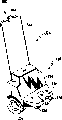
Fig. 6 is the perspective view of motorization propulsion system as shown in Figure 5, shows that this motorization propulsion system comprises a shell, the handle in obliquity, a plurality of wheel and an a pair of hook at raised position;
Fig. 7 is the view that is similar to Fig. 6, shows that handle moves to vertical substantially position, causes that this is moved down into a lower position to hook;
Fig. 8 is the view that is similar to Fig. 6, shows that the part of bedstead comprises that a cross bar and a pair of hook are connected on this cross bar after moving on to lower position;
Fig. 9 be similar to Fig. 5 removal the bed a part after view, show that a hook is moved to the lower position on the cross bar that is connected to bedstead;
Figure 10 is the sketch map of motorization propulsion system as shown in Figure 5, shows that this motorization propulsion system comprises that is coordinated hook mobile linked system between raised position (drawing with solid line) and lower position (with dashed lines draws);
Figure 11 is the lateral elevational view of the motorization propulsion system that is connected to bed of the bed of most preferred embodiment and another set of embodiment;
Figure 12 is the perspective view of motorization propulsion system as shown in figure 11, shows that this motorization propulsion system comprises a shell, the handle in obliquity, a plurality of wheel and the ball at lower position;
Figure 13 is the view that is similar to Figure 12, shows that handle moves to vertical substantially position, causes ball to be moved upwards up to the position of a rise;
Figure 14 is the view that is similar to Figure 12, shows that the part of bedstead comprises a pillar and a ball-and-socket that is connected on this pillar, and ball is positioned in the ball-and-socket after moving on to raised position;
Figure 15 be similar to Figure 14 removal the view after the part of bed, display ball is moved to the raised position in the ball-and-socket on the bedstead; With
Figure 16 is the sketch map of motorization propulsion system as shown in figure 11, shows that this motorization propulsion system comprises that provides the linked system that ball is moved between lower position (drawing with solid line) and raised position (with dashed lines draws).
The specific embodiment
Shown in Figure 1 is according to the patient support or the bed 10 of most preferred embodiment of the present invention.Bed 10 comprises that a bedstead 12, one place being used on the bedstead 12 to define the have a rest mattress 14, on surface 16 of patient and be connected to first patient's confinement plate of bedstead 12 or claim baffle head 18, one to be connected to second patient's confinement plate of bedstead 12 or claim foot baffle plate 20 and a pair ofly be connected to the 3rd patient's confinement plate of bedstead 12 or claim gusset hurdle 22.As shown in Figure 3 and Figure 4, the propulsion system 24 of most preferred embodiment outfit is connected to bedstead 12 and baffle head 18.The propulsion system 24 that is equipped with helps medical personnel's moving bed 10 between the not chummery of medical institutions or place.According to this most preferred embodiment, propulsion system 24 comprises a propulsion plant 26, framework 28 and one are configured as framework 28 are connected to the connecting device on baffle head 18 and the bedstead 12 or claim adapter 30, so medical personnel can be connected propulsion system 24 or separate with beds 10.
As shown in Figure 1, bedstead 12 comprises that a castor 32 connects under(-)chassis 34 thereon, a baffle head 18, foot baffle plate 20 and gusset hurdle 22 all be connected thereon central frame 36 and the lifting arm 38 of a central frame 36 that is used for support base framework 34 tops, so central frame 36 reduction that can raise.Being suitable for raising the detailed description of the machinery that reduces central frame can be referring to No. 4,559,655, the United States Patent (USP) that applies for August 11 nineteen eighty-two of authorizing Peck, and the content of its announcement is combined in herein by reference clearly.
As shown in Figure 4, under(-)chassis 34 comprises one first longitudinal member 40, second longitudinal member 42 and a pillar 44 that is connected to and extends 40,42 of first, second longitudinal members.The termination 48,50 of first, second longitudinal member 40,42 includes castor seat 58,60.
As shown in Figure 4, each castor 32 comprises a support 62, a wheel 64 and a loop bar 66 that is rotatably connected on the support 62.Loop bar 66 extends upward the collar 54,56 that passes attachment strut 46 respectively and the castor seat 58,60 of under(-)chassis 34, so the collar 54,56 is placed in around the low side of castor seat 58,60 and is laid on the support 62 of castor 32.Like this, for attachment strut 46 being connected to first, second longitudinal member 40,42, castor 32 need be taken off from bedstead 12, the collar 54,56 of attachment strut 46 is placed in the low side around castor seat 58,60, then loop bar 66 is put back to castor seat 58,60.Like this, just can improve bed 10 with attachment strut 46, propulsion system 24 just can be applied in medical institutions' moving bed 10 everywhere.According to other embodiment, attachment strut can adopt bolting, be welded or otherwise attached to under(-)chassis.
As shown in Figure 4, the framework 28 of propulsion system 24 comprises a shell 68, a framing component 70 and an a pair of support 71 that is connected to framing component 70 and shell 68 that is connected to shell 68.As shown in Figure 4, framework 28 further comprises a handle 78 that is placed in 80 li of a pair of sockets that is connected support 71.
Connecting device 30 comprise a pair of as Fig. 3 shown in Figure 4 be configured to first hook 82 that is connected to attachment strut 46 and a pair of as Fig. 3 shown in Figure 4 be connected to be configured on the handle 78 be connected to second of baffle head 18 and link up with 84.First hook 82 is connected to shell 68 by a framework 86 as shown in Figure 4.Framework 86 comprise with bolt or other securing members be fastened to first, second horizontal member 88,90 on the shell 68, extend the 3rd horizontal member 92 of 88,90 of first, second horizontal members, first, second vertical member 94,96 that extends downwards from the 3rd horizontal member and the 4th horizontal member 98 that extends 94,96 of first, second vertical members.
When propulsion system 24 is not connected with bed 10 and handle 78 when being positioned at obliquity, as shown in Figure 1, propulsion system 24 relies on the rolling of driving wheels 72 and driven pulley 74 to move to other bed from bed in medical institutions everywhere.When medical personnel want moved between positions bed 10 in medical institutions, just propulsion system 24 is connected on the bed 10.For propulsion system 24 being connected on the bed 10, propulsion system 24 is placed as shown in Figure 1 the place ahead of bed 10 head ends.When handle 78 is positioned at obliquity, propulsion system 24 is rolled along the head end of direction 128 towards bed 10, and therefore the plate part 110 of first hook 82 can touch recessed bar 52 as shown in Figure 2.Then, handle 78 is forwards shifted onto vertical substantially position with direction 124, and as shown in Figure 3, and second hook, 84 body 114 slides downwards with direction 120 along handle 78 and is placed in top edge 118 tops of baffle head 18 up to hook member 116.
In the rotation process of handle 78, as shown in Figure 3, driven pulley 78 is lifted from ground 33.Using propulsion system 24 in medical institutions everywhere in the process of moving bed 10, second hook 84 remains on this position with other parts of handle 78 and propulsion system 24 always.
For propulsion system 24 and bed 10 separate, second body part of linking up with 114 slides upward with direction 122, so hook member 116 no longer hooks top edge 118, so handle 78 can move away to obliquity on the baffle plate 18 from the head along direction 126.Handle 78 continues to move along direction 126 makes driven pulley 74 kiss the earths 33 to provide one to mention the pivoting point that hook 82 leaves recessed bar 52.Subsequently, propulsion system 24 pulls away from bed 10 with direction 130 as shown in Figure 1 and Figure 2.Propulsion plant 24 can then be shifted to the bed that another needs move or be put back to storeroom.
According to the present invention, propulsion system 24 can be used together with multiple bedstead configuration.Be equipped with and be used for each described bedstead configuration, the attachment strut that will hook 82 connect thereon.Described each attachment strut is all on the under(-)chassis that is connected to bed on the position or other members, so propulsion system 24 can be aimed in that second hook 84 is registered on the position that connects on the top edge of baffle head at each.
For example, a baffle head by the bedstead of vertical shift away from castor on, attachment strut is configured as being moved longitudinally to away from castor by hook portion of attachment strut, so the hook of second on the handle still can place on the top edge of described baffle head.Like this, propulsion system 24 just be configured as can and any amount of bedstead configuration use together, so propulsion system 24 become a kind of can with many different beds common apparatus of application together.Other the embodiment according to the present invention, other members that propulsion system is configured as the lower edge of foot baffle plate, head or foot baffle plate that can be connected to bed or bedstead are for example on the central frame.
Provide another embodiment of the motorization propulsion system 224 that is connected to bedstead 10, as Fig. 5, Fig. 8 and shown in Figure 9.The propulsion system 224 that provides helps medical personnel's moving bed 10 between the not chummery of medical institutions or place.So propulsion system 224 comprises that a propulsion plant 226, framework 228 and one are configured as other parts with propulsion system 224 and are connected to that medical personnel can be with propulsion system 224 and bed 10 connecting devices that are connected or separate or adapter 230 on the bedstead 10.
When wanting that bed 10 moved a long segment distance, propulsion system 224 is connected to bed 10 providing power to bed 10, so medical personnel needn't expend moving bed 10 necessary whole muscle power and energy between the different location of medical institutions.
As shown in Figure 8, under(-)chassis 34 comprises an attachment strut 244 that extends 48,50 of the terminations of adhering to first, second longitudinal member 40,42 separately.The attachment strut 244 ' of another embodiment has part such as Fig. 5 and shown in Figure 9 of a spill thereon.Connecting device 230 reduces and raises so that connect and bedstead 10 separately, as Fig. 6 and shown in Figure 8 and will describe in more detail hereinafter.
Propulsion plant 226 comprises a motor (on the figure draw), a motor controller (drawing on the figure) and a pair ofly is connected to framework 228 and is provided at medical institutions' driving wheel 254 on the motor of moving bed 10 necessary power and energy everywhere.Propulsion system 224 further comprises a pair of driven pulley 256 that is connected to framework 228.According to other embodiments of the invention, motor controller can be to be connected to the fixed controller on the handle, hand-held suspention controller, stick or the speed of any other suitable control motor and/or the controller of direction of band control handle, button or switch.
Be schematically shown as Fig. 8 and Figure 10, the framework 228 of propulsion system 224 comprises a shell 250, a framing component 252 and an a pair of support 258,260 that is connected to framing component 252 that is connected to shell 250.Propulsion system 224 comprises that further one comprises handle 264, the head rod 266 that is pivotally connected to handle 264 that is pivotally connected to support 258 and be pivotally connected to support 260 and the linked system 262 of second connecting rod 268 of head rod 266 (schematically drawing) in Figure 10.According to other optional embodiment, use the connecting rod that different size is arranged, so the distance that connecting device moves can be because the concrete application of each optional embodiment be different with geometry with direction.Further, according to other optional embodiment, more multi-link bar is employed different distances and the direction that moves because of the concrete application of each optional embodiment and the needed connecting device of geometry to obtain.
As Fig. 5, Fig. 8 and shown in Figure 9, connecting device 230 comprises that a pair of being configured as is connected to attachment strut 244,244 ' hook 270.Hook 270 is connected to second connecting rod 268, as shown in figure 10.Hook 270 comprises that one is connected to being configured as of plate part 272 with the plate part 272 that is welded or otherwise attached to second connecting rod 268 and one and hooks attachment strut 244,244 ' sweep 274.According to other embodiment, can use other connecting devices such as a pair of ball and ball-and-socket device, hitch pin, latch with and known other connecting devices of those skilled in that art.
When propulsion system 224 was not connected on the bed 10, propulsion system 224 moved on to another from bed by the rolling of driving wheel 254 and driven pulley 256 everywhere in medical institutions when handle 264 moves on to obliquity.When medical personnel wanted between different location in medical institutions moving bed 10, propulsion system 224 just was connected on the bed 10.For propulsion system 224 is connected with bed 10, propulsion system 224 is placed in the place ahead of bed 10 head end, as shown in Figure 5.When handle 264 is in obliquity, propulsion system 224 is rolled towards the head end of bed 10 with direction 76, therefore links up with 270 plate part 272 and touches attachment strut 244,244 '.Subsequently, handle 264 is forwards shifted onto vertical substantially position with direction 277, as Fig. 5, shown in Figure 10.
During turning handle 264, hook 270 drops to as Fig. 7, shown in Figure 8 dipping from raised position as shown in Figure 6, attachment strut 244,244 ' is fastened in the sweep 274 of hook 270.By first, second connecting rod 266,268, the mobile phase harmony of the mobile and handle 264 of hook 270.When handle 264 rotates forward, first pole 278 that head rod 266 promotes second connecting rod 268 travels forward, and causes second connecting rod 268 to rotate along clockwise direction.Because link up with 270 ends that are connected to second connecting rod 268, they also are docile and obedient clockwise and rotate and move down with respect to ground 33.This is downward to move and will link up with 270 and place the attachment strut 244,244 ' of bedstead 10 to go up so that propulsion system 224 is connected with beds 10.
As shown in figure 10, propulsion system 224 comprises that further is configured as a block sytem 280 that handle 264 is fixed on basic upright position.Block sytem 280 comprises that one is connected to framework 228 handle 264 is fixed on the latch 282 of basic upright position, unless so handle 264 can not to shift to obliquity latch 282 released.According to most preferred embodiment of the present invention, latch is one and is formed on hole on the handle 264 or spring biased pin (drawing on the figure) that groove (drawing on the figure) engages.According to other embodiments of the invention, can use the other forms of latch that common those of skill in the art were familiar with in the latch of other types such as sliding pin, hook, ball detent and this area.
Block sytem 280 further comprises a releasing device 284 that is connected to handle 264 and is connected to latch 282 by a cable wire (not drawing on the figure).In order to unclamp latch 282, releasing device 284 is shifted to lockset position of coupler, so the pin of latch 282 disengaging handle 264 is shifted to obliquity to allow handle 264.According to other embodiment, adopt the configuration of other any type of releasing device known to the common those of skill in the art in button, lever, switch or this area to realize release.Further, according to other embodiment, can adopt other releasing devices any other releasing device known to the common knack person in pedal, lever, button or this area for example on other members that are connected to propulsion system.
For propulsion plant 224 is removed from bed 10, after releasing device 284 unclamps latch 282 with handle 264 with direction 286 from the head plate washer 218 remove and move on to obliquity.The result that handle 264 moves along direction 286 is that first, second connecting rod 266,268 raises hook 270, so propulsion system 224 no longer is connected with the bedstead 12 of bed 10.Then, as shown in Figure 5, propulsion system 224 10 is drawn back along direction 288 from bed.Propulsion plant 224 can then be shifted to the bed that another needs move or be put back to storeroom.
Can use together with multiple different bedstead configuration according to propulsion system 224 of the present invention.Be equipped be used for each described bedstead configuration will link up with 270 attachment strut that connect thereon.Each described attachment strut all links to each other with under(-)chassis or other members of bed on a position, so propulsion system 224 can be aimed on the position that hook is connected on 270 attachment strut that are registered at each.Therefore propulsion system 224 is configured as with any amount of bedstead configuration and uses together, so propulsion system 224 is a kind of fexible units that can use together with many different beds.
Provide the another kind of optional embodiment of the motorization propulsion system 324 that is connected to bedstead 10, shown in Figure 11,14 and 15.Propulsion system 324 is used to help medical personnel's moving bed 10 between the not chummery of medical institutions or place.Propulsion system 324 comprises that 326, one frameworks 328 of a propulsion plant and one are configured as other parts with propulsion system 324 and are connected to connecting device 330 on the bedstead 10, so medical personnel can be connected propulsion system 324 or separate with bed 10.When wanting moving bed 10 certain distances, propulsion system 324 is connected with bed 10 gives beds 10 power is provided, so medical personnel need not expend moving bed 10 necessary whole muscle power and energy between the different places in medical institutions.
As shown in figure 14, under(-)chassis 34 comprises an optional embodiment pillar 344 that extends between the end 48,50 of separately first and second longitudinal members 40,42.Another optional embodiment pillar 344 ' is shown in Figure 11 and 15, and this pillar and first and second longitudinal components 40,42 link to each other and stretch out.Shown in Figure 14 and 15, each attached pillar 344,344 ' all comprises a ball-and-socket 345 under shed that is attached thereto.
Propulsion plant 326 comprises a motor (not shown), a motor controller (not shown), and a pair of and framework 328 be provided at medical institutions' driving wheel 354 of linking to each other of the motor of the essential power of moving bed 10 and energy everywhere.Propulsion system 324 further comprises a pair of driven pulley 356 that is connected with framework 328.According to other embodiments of the invention, motor controller can be a fixed controller that links to each other with handle, has control handle, the hand-held suspention controller of button or switch, stick, perhaps other any controllers that are suitable for controlling electromotor velocity and/or direction.
As being schematically shown among Figure 14 and Figure 16, the framework 328 of propulsion system 324 comprises 350, one frame parts 352 that are connected with shell 350 of a shell, and a pair of support 358,360 that links to each other with frame parts 352.Propulsion system further comprises a linked system 362 (schematically showing) in Figure 16, this linked system comprises a handle 364 pivotally connected with support 358, second connecting rod 368 pivotally connected with the pivotally connected head rod 366 of handle 364 and one and support 360 and head rod 366.According to other optional embodiment, can adopt connecting rod, so for separately optional embodiment, the distance that connecting device moves and direction can be different in concrete application and geometry with different size.In addition, according to other optional embodiment, thereby can adopt more connecting rod to obtain different distances and direction that these connecting devices of concrete application and geometry for separately optional embodiment move.
Connecting device 330 comprises a ball 370, and this ball is configured as in the ball-and-socket 345 that is received in attached pillar 344,344 ', as Figure 11, shown in 14 and 15.Ball 370 is connected with second connecting rod 368, as shown in figure 16.According to other embodiment, ball is connected to attached pillar, and ball-and-socket is parts on the propulsion plant.According to other embodiment, adopt other connecting device, hook for example, towing pin, latch and at known other connecting devices of those common those of skill in the art in the art.
When propulsion system 324 not and bed 10 is not connected, when handle 364 is moved to the position of an inclination, propulsion system 324 by roll drive take turns 354 and driven pulley 356 in medical institutions, moved to another from a bed.When medical personnel wished between each position in medical institutions moving bed 10, propulsion system 324 was connected on the bed 10.For propulsion system 324 is connected with bed 10, propulsion system 324 is placed in the place ahead of bed 10 head ends, as shown in figure 11.When handle 364 during in obliquity, 10 head end moves propulsion system 324 along direction 276 towards bed, and ball 370 just is placed in ball-and-socket 345 times like this.Then, handle 364 is pushed forward to vertical substantially position along direction 277, as Figure 11 and shown in Figure 16.
In the process of turning handle 364, ball 370 rises to a lifting position as shown in figure 13 from a lower position as shown in figure 12, and ball 370 just is placed in the ball-and-socket 345 of attached pillar 344,344 ', shown in Figure 14 and 15.Ball 370 move and handle 364 move through head rod 366 and second connecting rod 368 is coordinated mutually.When handle 364 rotates forward, head rod 366 promotes second connecting rod 368 makes second connecting rod 368 counterclockwise to rotate.Because ball 370 is connected to the end of second connecting rod 368, it also can counterclockwise rotate and upwards rise with respect to ground 33.This moves up and places 345 li of the ball-and-sockets of attached pillar 344,344 ' of bedstead 10 so that propulsion system 324 is linked to each other with bed 10 in ball 370.
Because the ball that ball 370 and ball-and-socket 345 provide and the configuration of ball-and-socket, so bed 10 and propulsion system 324 are connected by pivot.When turning around the corner, this connection allows 10 1 of propulsion system 324 and beds to rotate relative to another pivot, like this propulsion system 324 with regard to can not be when the turning undesired earth tremor.In addition, propulsion system 324 can be horizontal and vertical and transverse and longitudinal between the head end of other direction moving beds 10, this is by the relative position decision of propulsion system 324 with respect to bed 10.It is to be noted especially, because attached pillar 344 ' extends out more 324 of bedstead 10 and the propulsion systems that are present at interval from bedstead 10.This just allows propulsion system 324 with respect to bed 10 bigger corner to be arranged, and propulsion system 324 can promote the foot end of bed 10 with the angle perpendicular to the longitudinal axis of bed 10 like this.
As shown in figure 16, propulsion system 324 comprises that further is configured as a block sytem 380 that handle 364 is fixed on basic upright position.Block sytem 380 comprises that a handle 364 that is connected to framework 328 is fixed on the latch 382 of basic vertical direction, and handle 364 just can not be moved to obliquity like this, unless unclamp latch 382.According to most preferred embodiment of the present invention, this latch is a spring biased pin (not shown), and a hole or a groove in it and the handle 364 engage.According to other embodiments of the invention, other forms of latch, as sliding pin, the latch configuration that the general in the art those of skill in the art of hook, ball detent and other know all can adopt.
In order to remove propulsion system 324 from bed 10, releasing device 384 with latch 382 releases after, obliquity is removed and moved on to handle 364 with direction 286 from head of a bed baffle plate 218.Because the result that handle 364 moves in direction 386, first and second connecting rods 366,368 reduce ball 370, so propulsion system 324 will no longer be connected with the bedstead 12 of bed 10.Then, propulsion system 324 is drawn back from bed 10 with direction 288, as shown in figure 11.Propulsion plant 324 then can be shifted to the bed that another need move, or is placed on bunker.
According to disclosure of the present invention, propulsion system 324 is used together with a lot of different bedstead configurations.For each described bedstead configuration all provides a kind of attached pillar that can place ball 370 ball-and-socket in it that has.Each described attached pillar all is connected with bottom shore or other members of bed on a position, and like this, propulsion system 324 just can be aimed on the position that ball 370 is registered to fit in the ball-and-socket.Therefore, propulsion system 324 is configured to and can uses together with any amount of bedstead configuration, and propulsion system 324 is a kind of fexible units that can use together with many different beds like this.
According to other embodiments of the invention, a kind of suitable attachment strut 244,244 ', 344,344 ' is connected to the foot end of bedstead 10.Therefore, each propulsion system 224,324 all can be connected to the foot end of bedstead 10.
Claims (13)
1. a propulsion system that is configured to the removing patient brace table is characterized in that, this propulsion system comprises:
One for patient support mobile provide power propulsion plant and
One is configured to the adapter that can dividually described propulsion system be connected to patient support, this adapter comprises first parts that are suitable for the first distance connection patient support on distance ground, with second parts that are suitable for being connected than the bigger second distance of first distance on distance ground patient support, one of them of at least the first parts and second parts is adjustable.
2. the propulsion system described in claim 1 is characterized in that, wherein second parts are suitable for being connected to patient's confinement plate of patient support, and first parts are suitable for being connected to the under(-)chassis of patient support.
3. the propulsion system described in claim 1, it is characterized in that, this system further comprises a vertically extending handle, wherein propulsion plant comprises a framework and a driven wheel that is connected to framework, vertically extending handle is connected to framework, and second parts are connected to vertically extending handle.
4. the propulsion system described in claim 3 is characterized in that, wherein said second parts are to be slidably connected on the vertically extending handle.
5. the propulsion system described in claim 1 is characterized in that, wherein said first parts are hook-shaped, and is suitable for being hooked on the bedstead of patient support.
6. the propulsion system described in claim 5 is characterized in that, wherein said second parts are hook-shaped, and is suitable for being hooked on patient's confinement plate of patient support.
7. the propulsion system described in claim 1, it is characterized in that, this system further comprises a framework and a plurality of wheels that link to each other with framework, wherein propulsion plant is connected to framework, and a plurality of wheels contact with ground and are suitable for allowing propulsion plant to be rolled to another patient support from a patient support.
8. the propulsion system described in claim 7 is characterized in that, this system further comprises a handle, and this handle is connected with framework so that allow the user to promote propulsion system.
9. one kind is configured to mobile propulsion system with patient support of the patient's confinement plate that includes a head portion, it is characterized in that this propulsion system comprises:
Mobile propulsion plant and the adapter that power is provided for patient support,
Described adapter comprises first parts and second parts that are suitable for being connected than the bigger second distance of first distance in distance patient support that are suitable for the first distance connection patient support on distance ground, one of them of at least the first parts and second parts is adjustable, and one of them of at least the first parts and second parts is configured as the head portion that is connected to patient's confinement plate.
10. the propulsion system described in claim 9 is characterized in that, the another one parts of wherein said adapter further are suitable for being connected to the under(-)chassis of patient support.
11. the propulsion system described in claim 9, it is characterized in that, wherein said propulsion plant comprises a framework, a driven wheel and a vertically extending handle that is connected to framework, and adapter comprises first parts that are suitable for being connected to patient's confinement plate and vertically extending handle.
12. the propulsion system described in claim 11 is characterized in that, wherein said vertically extending handle is configured to the top that extends to patient's confinement plate from the framework of propulsion plant.
13. the propulsion system described in claim 9 is characterized in that, first parts of described at least adapter and one of them of second parts are suitable for being connected to the head portion of patient's confinement plate.
Applications Claiming Priority (4)
| Application Number | Priority Date | Filing Date | Title |
|---|---|---|---|
| US20340100P | 2000-05-11 | 2000-05-11 | |
| US60/203,401 | 2000-05-11 | ||
| US21861200P | 2000-07-17 | 2000-07-17 | |
| US60/218,612 | 2000-07-17 |
Publications (2)
| Publication Number | Publication Date |
|---|---|
| CN1438864A CN1438864A (en) | 2003-08-27 |
| CN1205904C true CN1205904C (en) | 2005-06-15 |
Family
ID=26898574
Family Applications (1)
| Application Number | Title | Priority Date | Filing Date |
|---|---|---|---|
| CN01810594.7A Expired - Fee Related CN1205904C (en) | 2000-05-11 | 2001-05-11 | Motorized propulsion system for a bed |
Country Status (7)
| Country | Link |
|---|---|
| US (2) | US7021407B2 (en) |
| EP (1) | EP1284709A2 (en) |
| JP (1) | JP2004512861A (en) |
| CN (1) | CN1205904C (en) |
| AU (1) | AU2001259732A1 (en) |
| CA (1) | CA2408087A1 (en) |
| WO (1) | WO2001085086A2 (en) |
Families Citing this family (80)
| Publication number | Priority date | Publication date | Assignee | Title |
|---|---|---|---|---|
| US7014000B2 (en) | 2000-05-11 | 2006-03-21 | Hill-Rom Services, Inc. | Braking apparatus for a patient support |
| US7018157B2 (en) * | 2001-09-20 | 2006-03-28 | Hill-Rom Services, Inc. | Powered transport apparatus for a bed |
| EP1437996A1 (en) | 2001-10-26 | 2004-07-21 | Daniel Johnson | Hospital bed power-assist |
| US7134515B2 (en) * | 2002-01-07 | 2006-11-14 | Lenkman Thomas E | Utility transport system |
| US6938711B2 (en) * | 2002-11-06 | 2005-09-06 | Mark Chandler Kime | Freestanding self-propelled device for moving objects |
| US7389836B2 (en) | 2003-09-23 | 2008-06-24 | Dane Industries, Inc. | Power-assisted cart retriever with attenuated power output |
| CA2447019A1 (en) * | 2003-10-27 | 2005-04-27 | Alistair Jenkins | Motorized towing apparatus |
| US7117967B2 (en) * | 2004-04-27 | 2006-10-10 | Kidd William W | Wheel chair apparatus and method |
| US7594284B2 (en) * | 2004-05-25 | 2009-09-29 | Nu Star Inc. | Transport aid for wheeled support apparatus |
| US20050279537A1 (en) * | 2004-06-18 | 2005-12-22 | Ken Nguyen | Motorized vehicle for maneuvering another wheeled apparatus |
| US20060016009A1 (en) * | 2004-07-22 | 2006-01-26 | Sean Mannix | Steering system for medical transport cart |
| CN1732875B (en) * | 2004-08-10 | 2010-06-16 | 医疗器具澳大利亚有限公司 | Driving wheel assembly |
| US20060254834A1 (en) * | 2005-05-11 | 2006-11-16 | Alfred Dassler | Method and apparatus for moving a bed |
| US7464776B2 (en) * | 2005-06-10 | 2008-12-16 | Textron Innovations | Motorized vehicle |
| ITBO20050770A1 (en) * | 2005-12-16 | 2007-06-17 | Ferno Washington Italia Srl | ASSISTED LOADER FOR A STRETCHER |
| US8555433B2 (en) * | 2005-12-16 | 2013-10-15 | Ferno-Washington, Inc. | Devices for the assisted loading of a stretcher |
| US7419019B1 (en) | 2006-03-23 | 2008-09-02 | Safe-T-Care Manufacturing, Co., Inc. | Power assist apparatus for use with a hospital bed |
| US20070221419A1 (en) * | 2006-03-27 | 2007-09-27 | Willis Douglas G | Detachable drive unit for mobile carriage |
| KR20090006161A (en) * | 2006-04-17 | 2009-01-14 | 케이씨아이 라이센싱 인코포레이티드 | System and method for bed transport |
| US7886377B2 (en) | 2006-10-13 | 2011-02-15 | Hill-Rom Services, Inc. | Push handle with rotatable user interface |
| US7882582B2 (en) | 2006-10-13 | 2011-02-08 | Hill-Rom Services, Inc. | User interface and control system for powered transport device of a patient support apparatus |
| JP4363455B2 (en) * | 2007-04-19 | 2009-11-11 | トヨタ自動車株式会社 | Traveling device |
| US7865983B2 (en) * | 2007-04-26 | 2011-01-11 | Hill-Rom Services, Inc. | Patient care equipment support transfer system |
| EP2033610A3 (en) | 2007-09-06 | 2009-11-04 | Holdingselskabet MKR Finans ApS | Transport system including a drive unit |
| DE202008017929U1 (en) | 2007-09-06 | 2011-02-24 | U-B-Let A/S | Transport system with a towing unit |
| US7712558B2 (en) * | 2007-09-06 | 2010-05-11 | Mh Logistics Corp. | Rolltainer transporter |
| GB2453536B (en) * | 2007-10-08 | 2012-07-18 | Nissan Motor Iberica Sa | Improvements in or relating to handling test rigs |
| US20090152826A1 (en) * | 2007-12-18 | 2009-06-18 | Jose Freitas Silva | Cargo cart with hitch for wheeled mobility device |
| US7789187B2 (en) | 2008-01-29 | 2010-09-07 | Hill-Rom Services, Inc. | Push handle with pivotable handle post |
| US8113305B1 (en) * | 2008-05-22 | 2012-02-14 | Flowers Ip Llc | Powered patient transport vehicle |
| US8684373B2 (en) * | 2008-09-23 | 2014-04-01 | Dane Technologies, Inc. | Cart moving machine |
| EP2269889A1 (en) * | 2009-06-30 | 2011-01-05 | Movexx International B.V. | Adaptor for a carrier rolling on swivel wheels |
| US10314754B2 (en) | 2009-08-05 | 2019-06-11 | B & R Holdings Company, Llc | Patient care and transport assembly |
| US8516637B2 (en) * | 2009-08-05 | 2013-08-27 | B & R Holdings Company, Llc | Patient care and transport assembly |
| US9010771B2 (en) | 2009-11-10 | 2015-04-21 | Dane Technologies, Inc. | Utility machine with dual-mode steering |
| EP2353964A2 (en) | 2010-01-13 | 2011-08-10 | U-B-Let A/S | Driving device for example for hospital bed |
| DE102010005696A1 (en) * | 2010-01-25 | 2011-07-28 | Brügmann und Freyermuth OHG "cad.Kat"- und "Euro Trax" Sonderkonstruktionen, 24159 | Lifting hook for supporting facilities, such as boat trailers and supporters, has motor and two motor-driven wheels, where wheels are mounted on axle, and coupling device is arranged against operating rod behind wheels |
| US20110283456A1 (en) * | 2010-05-19 | 2011-11-24 | Fred Herman | Ingress/egress assist handle |
| NL1038227C2 (en) * | 2010-09-07 | 2012-03-08 | Drogenbroek Jan-Hein Van | MOVE. |
| SG195293A1 (en) | 2011-06-17 | 2013-12-30 | Austech And Design Pty Ltd | Lifting and transporting device for wheeled objects including hospital beds |
| SG11201401295RA (en) * | 2011-10-12 | 2014-05-29 | Austech And Design Pty Ltd | Lifting and transporting device including front load supporting castors and associated linkage system |
| JP5206896B2 (en) * | 2011-10-13 | 2013-06-12 | 株式会社豊田自動織機 | Bed conveyance auxiliary device and bed |
| US8781677B2 (en) | 2012-04-23 | 2014-07-15 | Hospital Therapy Products | High centering bases for hospital gurneys |
| JP5835127B2 (en) * | 2012-06-28 | 2015-12-24 | 株式会社豊田自動織機 | Auxiliary device for transporting bed and method of using the same |
| CZ309134B6 (en) * | 2012-08-29 | 2022-02-23 | Linet, Spol. S R.O. | Hospital bed drive system |
| US10004651B2 (en) | 2012-09-18 | 2018-06-26 | Stryker Corporation | Patient support apparatus |
| US9259369B2 (en) | 2012-09-18 | 2016-02-16 | Stryker Corporation | Powered patient support apparatus |
| KR101486881B1 (en) * | 2012-10-11 | 2015-01-29 | 한국생산기술연구원 | Moving Type Lifting Apparatus Including Torque Adjustable Driving Assistance Unit |
| JP6346936B2 (en) * | 2013-03-12 | 2018-06-20 | ライトラボ・イメージング・インコーポレーテッド | Data collection system and control device for data collection system |
| JP5998091B2 (en) * | 2013-03-26 | 2016-09-28 | Kyb株式会社 | Dolly drive assist unit |
| JP6023621B2 (en) * | 2013-03-26 | 2016-11-09 | Kyb株式会社 | Dolly drive assist unit |
| US9187301B2 (en) * | 2013-04-22 | 2015-11-17 | Jlg Industries, Inc. | Self-propel accessory |
| US8950524B2 (en) * | 2013-06-28 | 2015-02-10 | Sunpex Technology Co., Ltd. | Electric moving device for moving patient beds |
| GB201319711D0 (en) * | 2013-11-08 | 2013-12-25 | Univ Singapore | Retro-fit mobility unit |
| DE102014100451B4 (en) * | 2014-01-16 | 2017-04-06 | MAQUET GmbH | Device for moving a transporter of a patient support unit and arrangement with such a device |
| US9603764B2 (en) | 2014-02-11 | 2017-03-28 | Medline Industries, Inc. | Method and apparatus for a locking caster |
| US9333979B2 (en) | 2014-02-13 | 2016-05-10 | Avi Iron Solutions Ltd. | Auxiliary pusher device |
| WO2016041599A1 (en) * | 2014-09-18 | 2016-03-24 | Ideassociates (Iom) Ltd | A wheeled transportation device |
| US10406045B2 (en) | 2015-06-22 | 2019-09-10 | Stryker Corporation | Patient support apparatuses with navigation and guidance systems |
| US10406044B2 (en) * | 2015-06-25 | 2019-09-10 | Stryker Corporation | Person support apparatuses with drive controls |
| US10568792B2 (en) | 2015-10-28 | 2020-02-25 | Stryker Corporation | Systems and methods for facilitating movement of a patient transport apparatus |
| US10045893B2 (en) | 2015-12-22 | 2018-08-14 | Stryker Corporation | Patient transport apparatus with controllable auxiliary wheel assembly |
| US10603234B2 (en) | 2016-03-30 | 2020-03-31 | Stryker Corporation | Patient support apparatuses with drive systems |
| US10893988B2 (en) | 2016-05-26 | 2021-01-19 | Stryker Corporation | Patient support systems and methods for docking, transporting, sterilizing, and storing patient support decks |
| NL2017890B1 (en) * | 2016-11-29 | 2018-06-11 | Josh Ip Iii B V | Medical transport device, auxiliary drive, and method for transporting such a transport device |
| CN110177533B (en) * | 2017-01-13 | 2022-10-28 | 西门子医疗有限公司 | Transport device and method for operating such a transport device |
| DE102018122360A1 (en) * | 2018-09-13 | 2020-03-19 | Alber Gmbh | Auxiliary drive device for a wheelchair |
| FR3089786B1 (en) * | 2018-12-18 | 2020-12-04 | Ifp Energies Now | Detachable electric propulsion system for a rolling object, including a bed |
| FR3093918B1 (en) | 2019-03-18 | 2021-02-19 | Ifp Energies Now | Detachable electric propulsion system wheel gripping device for rolling object |
| FR3093916B1 (en) | 2019-03-18 | 2021-05-07 | Ifp Energies Now | Removable electric propulsion system wheel driving aid device for a rolling object |
| FR3093919B1 (en) | 2019-03-18 | 2021-02-19 | Ifp Energies Now | Detachable electric propulsion system wheel lifting device for rolling object |
| FR3093917B1 (en) | 2019-03-18 | 2021-02-19 | Ifp Energies Now | Detachable electric propulsion system wheel immobilizer for a rolling object |
| FR3102448B1 (en) | 2019-10-23 | 2021-10-08 | Ifp Energies Now | method and system of removable electric propulsion for a rolling object with a measuring means and a control means |
| FR3102447B1 (en) | 2019-10-23 | 2021-10-29 | Ifp Energies Now | Removable electric propulsion system for a rolling object with measuring and controlling means |
| FR3108302B1 (en) | 2020-03-19 | 2023-05-19 | Ifp Energies Now | Removable electric propulsion system for a rolling object comprising a foldable seating device |
| FR3108497B1 (en) | 2020-03-25 | 2023-05-19 | Ifp Energies Now | Removable electric propulsion system for a rolling object with a handlebar clearing device |
| FR3110888B1 (en) | 2020-05-29 | 2023-05-19 | Ifp Energies Now | Removable electric propulsion system for a rolling object with combined and simultaneous gripping and lifting means |
| FR3110887B1 (en) | 2020-05-29 | 2022-07-29 | Ifp Energies Now | Removable electric propulsion system for a rolling object with an automatic directional blocking means |
| FR3113235B1 (en) | 2020-08-04 | 2022-07-29 | Ifp Energies Now | Removable electric propulsion system for a rolling object - simultaneous and combined wheel gripping and lifting in the longitudinal direction |
| CN117338538B (en) * | 2023-12-04 | 2024-03-19 | 河北普康医疗设备有限公司 | Auxiliary medical frame for electric medical bed |
Family Cites Families (85)
| Publication number | Priority date | Publication date | Assignee | Title |
|---|---|---|---|---|
| US813213A (en) | 1904-11-10 | 1906-02-20 | Warren S Johnson | Motor-propelled vehicle. |
| US1598124A (en) | 1925-03-24 | 1926-08-31 | Evans Joshua | Motor attachment for carriages |
| US2635899A (en) | 1948-03-23 | 1953-04-21 | Jr John William Osbon | Invalid bed |
| US2710659A (en) * | 1952-04-04 | 1955-06-14 | Moederle Vasco | Wheel chair and tractor combination |
| DE1041210B (en) | 1955-12-12 | 1958-10-16 | Stiegelmeyer & Co Gmbh | Bed driver |
| US2999555A (en) | 1957-08-29 | 1961-09-12 | Harry W Brelsford | Motorized litter |
| US3004768A (en) | 1958-08-13 | 1961-10-17 | Columbus Auto Parts | Carrier for outboard motors |
| US3112001A (en) | 1959-11-19 | 1963-11-26 | Charles W Wise | Drive means for an invalid's bed |
| US3253668A (en) * | 1963-07-25 | 1966-05-31 | Fruehauf Corp | Separable wheeled units for vehiclizing containers |
| US3380546A (en) | 1966-02-14 | 1968-04-30 | Rodney R. Rabjohn | Traction drive for small vehicles |
| JPS4631490Y1 (en) | 1967-04-25 | 1971-10-30 | ||
| US3452371A (en) | 1967-10-16 | 1969-07-01 | Walter F Hirsch | Hospital stretcher cart |
| US3503466A (en) * | 1968-10-07 | 1970-03-31 | Judge E Rosander | Scaffold moving and guiding device |
| JPS47814U (en) | 1971-01-21 | 1972-08-08 | ||
| JPS4717495U (en) | 1971-03-26 | 1972-10-28 | ||
| US3770070A (en) | 1971-07-29 | 1973-11-06 | J Smith | Utility vehicle |
| US3730970A (en) | 1971-10-04 | 1973-05-01 | Minnesota Mining & Mfg | Terminal with grease retaining members |
| JPS4844792A (en) | 1971-10-10 | 1973-06-27 | ||
| JPS4854494A (en) | 1971-11-12 | 1973-07-31 | ||
| JPS4929855A (en) | 1972-07-13 | 1974-03-16 | ||
| US3814199A (en) | 1972-08-21 | 1974-06-04 | Cleveland Machine Controls | Motor control apparatus adapted for use with a motorized vehicle |
| US3876024A (en) | 1972-12-07 | 1975-04-08 | Said Charles S Mitchell To Sai | Motorized vehicle for moving hospital beds and the like |
| US3929354A (en) | 1974-12-19 | 1975-12-30 | Edward John Elkins | Adjustable drawbar |
| JPS539091A (en) | 1976-07-12 | 1978-01-27 | Yaesu Rehabili Co Ltd | Electrically operated wheeled carrier |
| GB1601930A (en) * | 1977-12-14 | 1981-11-04 | Icms Ltd | Devices for driving mobile trolleys |
| JPS57187521A (en) | 1981-05-09 | 1982-11-18 | Fagersta Ab | Corrosion-proof method for cooler and chimney of combustion facility |
| US4415049A (en) | 1981-09-14 | 1983-11-15 | Instrument Components Co., Inc. | Electrically powered vehicle control |
| JPS5863575A (en) | 1981-10-13 | 1983-04-15 | Kouyuu Kosan Kk | Omnidirectional running vehicle |
| US4566707A (en) | 1981-11-05 | 1986-01-28 | Nitzberg Leonard R | Wheel chair |
| SE431393B (en) | 1982-05-03 | 1984-02-06 | Permobil Ab | STEERABLE, ENGINE DRIVE WHEEL |
| US4559655A (en) | 1982-08-11 | 1985-12-24 | Hill-Rom Company, Inc. | Bed having articulated frame |
| JPS5938176A (en) | 1982-08-24 | 1984-03-01 | Mitsubishi Electric Corp | Travelling truck |
| US4475613A (en) | 1982-09-30 | 1984-10-09 | Walker Thomas E | Power operated chair |
| JPS60122561A (en) | 1983-12-06 | 1985-07-01 | 株式会社今仙電機製作所 | Conveyor instrument |
| US4584989A (en) | 1984-12-20 | 1986-04-29 | Rosemarie Stith | Life support stretcher bed |
| FR2582977B1 (en) | 1985-06-05 | 1987-07-31 | Albert Parolai | MOBILE BENCH WITH EXCLUSIVELY MECHANICAL OPERATIONS |
| IL77966A (en) | 1986-02-24 | 1991-03-10 | Propel Partnership 1987 | Wheelchair drive |
| US5094314A (en) | 1986-06-30 | 1992-03-10 | Yamaha Hatsudoki Kabushiki Kaisha | Low slung small vehicle |
| US4807716A (en) | 1987-02-09 | 1989-02-28 | Hawkins J F | Motorized carrying cart and method for transporting |
| US4811988A (en) | 1987-03-09 | 1989-03-14 | Erich Immel | Powered load carrier |
| US4771840A (en) | 1987-04-15 | 1988-09-20 | Orthokinetics, Inc. | Articulated power-driven shopping cart |
| JPH0284961A (en) | 1988-04-08 | 1990-03-26 | Hideji Okamoto | Mobile bed for escape |
| US5156226A (en) | 1988-10-05 | 1992-10-20 | Everest & Jennings, Inc. | Modular power drive wheelchair |
| CA2010543A1 (en) | 1989-03-17 | 1990-09-17 | Ryan A. Reeder | Motorized stretcher |
| WO1990011922A1 (en) | 1989-04-10 | 1990-10-18 | Rosecall Pty. Ltd. | Vehicle for conveying trolleys |
| US4949408A (en) | 1989-09-29 | 1990-08-21 | Trkla Theodore A | All purpose wheelchair |
| JP2876335B2 (en) | 1990-05-10 | 1999-03-31 | 有限会社タクマ精工 | Drive wheel lifting and lowering device for self-propelled bogie |
| US5117521A (en) | 1990-05-16 | 1992-06-02 | Hill-Rom Company, Inc. | Care cart and transport system |
| US5337845A (en) | 1990-05-16 | 1994-08-16 | Hill-Rom Company, Inc. | Ventilator, care cart and motorized transport each capable of nesting within and docking with a hospital bed base |
| US5083625A (en) | 1990-07-02 | 1992-01-28 | Bleicher Joel N | Powdered maneuverable hospital cart |
| US5121806A (en) | 1991-03-05 | 1992-06-16 | Johnson Richard N | Power wheelchair with torsional stability system |
| US5222567A (en) | 1991-04-26 | 1993-06-29 | Genus Inc. | Power assist device for a wheelchair |
| US5207286A (en) * | 1992-04-23 | 1993-05-04 | Mckelvey George P | Steerable wheelchair attachment with powered coupling means |
| JPH0650631A (en) | 1992-08-04 | 1994-02-25 | Kubota Corp | Heat pump device for both cooling and heating operations |
| US5439069A (en) | 1992-11-27 | 1995-08-08 | Beeler; Jimmy A. | Nested cart pusher |
| US5366036A (en) | 1993-01-21 | 1994-11-22 | Perry Dale E | Power stand-up and reclining wheelchair |
| US5477935A (en) | 1993-09-07 | 1995-12-26 | Chen; Sen-Jung | Wheelchair with belt transmission |
| US5495904A (en) | 1993-09-14 | 1996-03-05 | Fisher & Paykel Limited | Wheelchair power system |
| BE1007895A3 (en) | 1993-12-21 | 1995-11-14 | Elaut N V | Device for moving beds. |
| JP2758825B2 (en) | 1994-02-22 | 1998-05-28 | 山形日本電気株式会社 | Automatic transfer cart |
| GB9403848D0 (en) | 1994-03-01 | 1994-04-20 | Smiths Ind Public Ltd | Trolleys |
| US5651422A (en) * | 1994-04-22 | 1997-07-29 | The Center For Innovative Technology | Universal-fit, quick-connect power drive/steer attachment for wheelchair |
| SE502910C2 (en) | 1994-06-22 | 1996-02-19 | Mickey Joergen Behrendts | combination Roll |
| US5445233A (en) | 1994-08-04 | 1995-08-29 | Fernie; Geoffrey R. | Multi-directional motorized wheelchair |
| JPH08317953A (en) | 1995-05-26 | 1996-12-03 | Tokico Ltd | Device for transporting bed |
| US5898961A (en) | 1995-06-07 | 1999-05-04 | Hill-Rom, Inc. | Mobile support unit and attachment mechanism for patient transport device |
| FR2735019B1 (en) | 1995-06-09 | 1997-11-28 | Corona Soc | MOBILE ELEMENT, ESPECIALLY A HOSPITALIZATION BED, SUPPORTED ON THE GROUND BY SEVERAL STEERING LIFT WHEELS |
| JPH0924071A (en) | 1995-07-13 | 1997-01-28 | Tokico Ltd | Bed transport device |
| JPH0938155A (en) | 1995-08-02 | 1997-02-10 | Tokico Ltd | Bed conveyer |
| JPH0938154A (en) | 1995-08-02 | 1997-02-10 | Tokico Ltd | Bed conveyer |
| US6496991B1 (en) * | 1995-09-13 | 2002-12-24 | Ergodyne Corporation | Device for patient pullup, rollover, and transfer and methods therefor |
| US5934694A (en) | 1996-02-13 | 1999-08-10 | Dane Industries | Cart retriever vehicle |
| FR2746060B1 (en) | 1996-03-18 | 1998-05-15 | Ind Et Sport Sa | CONTROL EQUIPMENT FOR MOVING A TROLLEY IN MOTORIZED OR MANUAL OPERATION |
| JP3705378B2 (en) | 1996-07-01 | 2005-10-12 | ヤマハ発動機株式会社 | Electric wheelchair |
| US6070679A (en) | 1996-07-11 | 2000-06-06 | Lindbergh Manufacturing, Inc. | Powered utility cart having engagement adapters |
| JPH10146364A (en) | 1996-09-20 | 1998-06-02 | Toyota Autom Loom Works Ltd | Bed carrying vehicle |
| US5839528A (en) | 1996-09-30 | 1998-11-24 | Lee; John E. | Detachable motorized wheel assembly for a golf cart |
| JP3819525B2 (en) | 1997-03-28 | 2006-09-13 | 本田技研工業株式会社 | Ambulatory cart with auxiliary power |
| US6244366B1 (en) * | 1997-08-07 | 2001-06-12 | Smarte Carte, Inc. | Cart transporter |
| US6060328A (en) * | 1997-09-05 | 2000-05-09 | Advanced Micro Devices, Inc. | Methods and arrangements for determining an endpoint for an in-situ local interconnect etching process |
| US6062328A (en) | 1998-06-10 | 2000-05-16 | Campbell; Jeffery D. | Electric handcart |
| JP2000107230A (en) | 1998-10-09 | 2000-04-18 | S N Seiki:Kk | Fitting unit of stretcher |
| US6148942A (en) | 1998-10-22 | 2000-11-21 | Mackert, Sr.; James M. | Infant stroller safely propelled by a DC electric motor having controlled acceleration and deceleration |
| US6062060A (en) * | 1998-11-20 | 2000-05-16 | Nguyen; Tien | Tool kit for flaring metal tubes |
| US6330926B1 (en) | 1999-09-15 | 2001-12-18 | Hill-Rom Services, Inc. | Stretcher having a motorized wheel |
-
2001
- 2001-05-11 CN CN01810594.7A patent/CN1205904C/en not_active Expired - Fee Related
- 2001-05-11 CA CA002408087A patent/CA2408087A1/en not_active Abandoned
- 2001-05-11 US US09/853,802 patent/US7021407B2/en not_active Expired - Fee Related
- 2001-05-11 EP EP01933296A patent/EP1284709A2/en not_active Withdrawn
- 2001-05-11 WO PCT/US2001/015217 patent/WO2001085086A2/en not_active Application Discontinuation
- 2001-05-11 AU AU2001259732A patent/AU2001259732A1/en not_active Abandoned
- 2001-05-11 JP JP2001581741A patent/JP2004512861A/en active Pending
-
2006
- 2006-03-28 US US11/391,005 patent/US7481286B2/en not_active Expired - Fee Related
Also Published As
| Publication number | Publication date |
|---|---|
| WO2001085086A2 (en) | 2001-11-15 |
| JP2004512861A (en) | 2004-04-30 |
| US20020084116A1 (en) | 2002-07-04 |
| US20060175100A1 (en) | 2006-08-10 |
| US7481286B2 (en) | 2009-01-27 |
| US7021407B2 (en) | 2006-04-04 |
| CA2408087A1 (en) | 2001-11-15 |
| WO2001085086A3 (en) | 2002-03-21 |
| AU2001259732A1 (en) | 2001-11-20 |
| CN1438864A (en) | 2003-08-27 |
| EP1284709A2 (en) | 2003-02-26 |
Similar Documents
| Publication | Publication Date | Title |
|---|---|---|
| CN1205904C (en) | Motorized propulsion system for a bed | |
| EP2429473B1 (en) | Transport apparatus | |
| CN1903154A (en) | Medical use carrier for transferring patient | |
| CN1208340A (en) | Apparatus for handling incapacitated patients | |
| CN1874922A (en) | Lifting device and method for use the same | |
| CN1151281A (en) | Sick or wounded patient bed having separable frame and moving/lifting apparatus for separable frame | |
| CN200945361Y (en) | Movable folding type rotary rocking house | |
| CN211131120U (en) | Movable CT scanning equipment | |
| CN1718489A (en) | Folding handling car for stairs and flat land dual purpose | |
| CN2389811Y (en) | Collapsible perambulator | |
| DE2228898A1 (en) | FLOOR-HANGED SICKNESS BED FOR HOSPITALS | |
| CN110786186A (en) | Intelligent agriculture plants big-arch shelter with removing operation frame | |
| CN212016012U (en) | Turning mechanism for paralyzed patient nursing bed | |
| CN214181644U (en) | Auxiliary recovery equipment for anesthesia department | |
| CN210205176U (en) | Turn-over type nursing cleaning robot | |
| CN212799485U (en) | Handcart boosting bracket mechanism and handcart boosting electric vehicle | |
| CN219480635U (en) | Operation transferring bed | |
| KR101952343B1 (en) | Driving apparatus type articulation of over obstacle | |
| JP2000515470A (en) | Elevating work platform | |
| CN219700446U (en) | Postoperative rehabilitation training device | |
| CN2364196Y (en) | Vehicle-mounted fire-fighting ladder | |
| CN2210644Y (en) | Wheeled stretcher for patients changing hospital beds | |
| CN216837029U (en) | Building construction elevator fixing device | |
| CN2237629Y (en) | Crane lifter | |
| CN115230790B (en) | Material transfer device is used in railway equipment processing |
Legal Events
| Date | Code | Title | Description |
|---|---|---|---|
| C06 | Publication | ||
| PB01 | Publication | ||
| C10 | Entry into substantive examination | ||
| SE01 | Entry into force of request for substantive examination | ||
| C14 | Grant of patent or utility model | ||
| GR01 | Patent grant | ||
| C19 | Lapse of patent right due to non-payment of the annual fee | ||
| CF01 | Termination of patent right due to non-payment of annual fee |