CN1205842C - Encoding method and device, decoding method and device, and recording medium - Google Patents
Encoding method and device, decoding method and device, and recording medium Download PDFInfo
- Publication number
- CN1205842C CN1205842C CNB988007819A CN98800781A CN1205842C CN 1205842 C CN1205842 C CN 1205842C CN B988007819 A CNB988007819 A CN B988007819A CN 98800781 A CN98800781 A CN 98800781A CN 1205842 C CN1205842 C CN 1205842C
- Authority
- CN
- China
- Prior art keywords
- signal
- coding
- code
- channel
- sound channel
- Prior art date
- Legal status (The legal status is an assumption and is not a legal conclusion. Google has not performed a legal analysis and makes no representation as to the accuracy of the status listed.)
- Expired - Fee Related
Links
Images


Classifications
-
- H—ELECTRICITY
- H04—ELECTRIC COMMUNICATION TECHNIQUE
- H04H—BROADCAST COMMUNICATION
- H04H20/00—Arrangements for broadcast or for distribution combined with broadcast
- H04H20/86—Arrangements characterised by the broadcast information itself
- H04H20/88—Stereophonic broadcast systems
-
- G—PHYSICS
- G10—MUSICAL INSTRUMENTS; ACOUSTICS
- G10L—SPEECH ANALYSIS OR SYNTHESIS; SPEECH RECOGNITION; SPEECH OR VOICE PROCESSING; SPEECH OR AUDIO CODING OR DECODING
- G10L19/00—Speech or audio signals analysis-synthesis techniques for redundancy reduction, e.g. in vocoders; Coding or decoding of speech or audio signals, using source filter models or psychoacoustic analysis
- G10L19/008—Multichannel audio signal coding or decoding using interchannel correlation to reduce redundancy, e.g. joint-stereo, intensity-coding or matrixing
-
- G—PHYSICS
- G11—INFORMATION STORAGE
- G11B—INFORMATION STORAGE BASED ON RELATIVE MOVEMENT BETWEEN RECORD CARRIER AND TRANSDUCER
- G11B20/00—Signal processing not specific to the method of recording or reproducing; Circuits therefor
- G11B20/10—Digital recording or reproducing
-
- H—ELECTRICITY
- H04—ELECTRIC COMMUNICATION TECHNIQUE
- H04H—BROADCAST COMMUNICATION
- H04H40/00—Arrangements specially adapted for receiving broadcast information
- H04H40/18—Arrangements characterised by circuits or components specially adapted for receiving
- H04H40/27—Arrangements characterised by circuits or components specially adapted for receiving specially adapted for broadcast systems covered by groups H04H20/53 - H04H20/95
- H04H40/36—Arrangements characterised by circuits or components specially adapted for receiving specially adapted for broadcast systems covered by groups H04H20/53 - H04H20/95 specially adapted for stereophonic broadcast receiving
- H04H40/45—Arrangements characterised by circuits or components specially adapted for receiving specially adapted for broadcast systems covered by groups H04H20/53 - H04H20/95 specially adapted for stereophonic broadcast receiving for FM stereophonic broadcast systems receiving
- H04H40/72—Arrangements characterised by circuits or components specially adapted for receiving specially adapted for broadcast systems covered by groups H04H20/53 - H04H20/95 specially adapted for stereophonic broadcast receiving for FM stereophonic broadcast systems receiving for noise suppression
-
- H—ELECTRICITY
- H04—ELECTRIC COMMUNICATION TECHNIQUE
- H04S—STEREOPHONIC SYSTEMS
- H04S1/00—Two-channel systems
- H04S1/007—Two-channel systems in which the audio signals are in digital form
Abstract
A recording medium for recording a code string comprising: encoded signals of an A-channel, i.e. (L+R)/2, generated from L- and R-channels; encoded signals of a B-channel, i.e. either one of L- and R-channels or (L-R)/2; channel constitution data which are the information for selecting B-channel signals; and encoding parameters. The A-channel is used for such signals that can be reproduced with a reproducing device of an old standard type and the B-channel is used for such signals that can be reproduced with a reproducing device of a new standard type. The reproducing device of a new standard type can reproduce both A- and B-channel signals. Encoding and decoding which realize multichannel devices by expanding the new standard while making possible the reproduction with the reproducing device of an old standard type, wherein the deterioration of tone quality is reduced by minimizing the quantization noise produced by encoding.
Description
Technical field
Preferable coding method and device when the present invention relates to a kind of spread coded signals form, corresponding therewith coding/decoding method and device, and the recording medium that writes down encoded signal.
Background technology
In the past, as the medium that can write down this class signal (hereinafter referred to as audio signal) of encoded aural information or acoustic information, proposed such as this class signal recording medium of magneto optical disk.All ways of above-mentioned audio signal being carried out high efficient coding are arranged, wherein adducible example, so-called transition coding is arranged, promptly unit divides into groups the audio signal on the time shaft in required time, with the time shaft signal transformation (spectrum transformation) of each such grouping is signal on the frequency axis, and be segmented into a plurality of frequency bands, the grouping frequency-division section mode that each frequency band is encoded; Or so-called subband coding (サ Block バ Application De コ デ-イ Application グ: SBC),, but be segmented into the non-grouping frequency-division section mode that a plurality of frequency bands are encoded promptly not to the grouping of the audio signal on the time shaft.In addition, also can consider the high efficient coding way of above-mentioned subband coding and transition coding combination.At this moment, for example by after above-mentioned subband coding carries out the frequency band segmentation, be signal on the frequency axis, and this each frequency band through spectrum transformation is encoded each band signal spectrum transformation.
Here, as the frequency band segmentation filter that is used for above-mentioned subband coding, quadrature mirror filter) so-called QMF (Quadrature Mirror filter: filter such as is for example arranged, this QMF filter is at document " phonetic coding of frequency-division section mode " (" Digital coding of speech in subbands " R.E.Crochiere, Bell Syst.Tech.J., Vol.55, No.8,1976) narration arranged.This QMF filter is that frequency band is divided into 2 sections device by equal bandwidth, and this filter is characterized in that, does not have so-called aliasing to take place during the synthetic above-mentioned subsequently frequency band through segmentation.And document " Multi-part mirror filter---a kind of new subband coding technology " (" Polyphase Quadrature filters-A new subbandcoding techique ", Joseph H.Rothweiler, ICASSP 83, and the filter frequency-division section technology of equiband BOSTON) then has been discussed.This Multi-part mirror filter is characterized in that, once can finish frequency-division section when being a plurality of frequency band of equiband with signal subsection.
For above-mentioned spectrum transformation, for example have that the unit interval (frame) is divided into groups input audio signal in accordance with regulations, discrete Fourier transform (Discrete Fourier Transform:DFT), discrete cosine transform (Discrete Cosine Transform:DCT), distortion discrete cosine transform (ModifiedDiscrete Cosine Transform:MDCT) etc. are carried out in each this grouping, are the sort of spectrum transformation of frequency axis with time axis conversion.In addition, for above-mentioned MDCT, document " adopts the frequency-division section/transition coding based on the bank of filters of eliminating the design of time domain aliasing " (" Subband/Transform Coding Using Filter Bank Designs Basedon Time Domain Aliasing Canellation ", J.P.Princen A.B.Bradley, Univ.of Surrey Royal Melbourne Inst.of Tech.ICASSP 1987) in narration is arranged.
And utilize above-mentioned DFT or DCT when waveform signal is carried out the method for spectrum transformation, when the time block of forming by for example M sampled data carries out conversion (is transform block to call this in the following text), can obtain the individual independently real data of M.Here, in order to alleviate the connection distortion between transform block, between adjacent transform block, make M1 sampled data overlapping usually respectively, these DFT or DCT just become, on average can obtain M real data to (M-M1) individual sampled data, so, be that this M real data is quantized and encodes subsequently.
Different therewith, when utilizing above-mentioned MDCT, can obtain independently M real data according to making M 2M the sample that sampled data is overlapping between adjacent transform block respectively as the spectrum transformation method.Specifically, when using MDCT, on average can obtain M real data to M sampled data, be that this M real data is quantized and encodes subsequently.Decoding device can make each transform block relevant synthetic through the waveform key element that inverse transformation obtains according to the coding that utilizes MDCT to obtain like this, rebuilds waveform signal.
And make the used transform block lengthening of above-mentioned spectrum transformation, and bring frequency resolution to improve usually, concentration of energy is in this result of specific frequency spectrum signal component.So, if utilize above-mentioned MDCT, make between adjacent transform block respectively the longer transformation block length of overlapping half sampled data carry out spectrum transformation, and the number of the spectrum signal composition that is obtained does not increase with respect to the sampled data number of the original time axle, just can carry out efficient high coding than with DFT or DCT the time.And it is sufficiently long overlapping to manage to make adjacent transform block all to have, and can also alleviate the connection distortion between the waveform signal transform block.But make the used transform block lengthening of conversion, just need the used service area of conversion more again, thereby becoming obstacle aspect the miniaturizations such as playback reproducer, especially improving aspect the semiconductor integrated level comparatively at need, adopt longer transform block can cause cost to increase, thereby need to pay close attention to.
As indicated above, quantize by the signal component that makes filter or spectrum transformation segmentation in each frequency band, can control the frequency band that produces quantization noise, so can utilize characteristic such as so-called masking effect, carry out the higher coding of efficient acoustically.And before wherein quantizing, each frequency band can be encoded more efficiently if by the maximum of signal component absolute value in this frequency band for example, sampled data is carried out normalized words.
Here, the frequency division width when for example each signal component that audio signal is obtained through the frequency band segmentation quantizes preferably adopts the frequency bandwidth of having considered human auditory's characteristic.Specifically, preferably utilize the wide more the sort of bandwidth that is called critical band (Network リ テ ィ カ Le バ Application De) of high band frequency band, audio signal is segmented into a plurality of frequency bands (for example 25 frequency bands).When at this moment each frequency band data is encoded, can distribute (PVC Star ト ア ロ ケ-シ ヨ Application) encode according to the position configuration of each frequency band regulation or the position of each band-adaptive.For example when above-mentioned MDCT handles the coefficient data that obtains according to last rheme allocated code, just each above-mentioned transform block is handled each the frequency band MDCT coefficient data that obtains through MDCT, encode by adaptive minute ligancy.For the position distribution technique, knowing has following 2 kinds of technology.
For example, document " voice signal Adaptive Transform Coding " (" Adaptive Transform Coding ofSpeech Signals ", R.Zelinski and P.Noll, IEEE Transactions of Acoustics, Speech, and Signal Processing, vol.ASSP-25, No.4, August 1977) in, carry out the position according to the scale of each band signal and distribute.This mode, quantization noise spectrum is smooth, noise energy is minimum, but aspect the sense of hearing owing to do not utilize masking effect, thereby the actual noise sense is not the best.
And for example " the critical band encoder---require relevant digital coding with auditory system consciousness " (" Thecritical band coder--digital encoding of the perceptual requirementsof the auditory system ", M.A.Kransner MIT, ICASSP 1980) in, then discussed by utilizing auditory masking, to distribute this technology in the position that obtains the required signal noise ratio of each frequency band and fix.But this technology, even if by the sinusoidal wave occasion of measuring characteristic of importing, characteristic value is fixing so not good because of the position distribution yet.
In order to address these problems, a kind of like this high efficient coding method has been proposed, whole positions that will can be used for distributing the position are managed to cut apart and are used for the predetermined fixed bit allocation model part of each fritter and rely on each block signal size carrying out an assigned portions, the ration of division of this moment is depended on and the related signal of input signal, the collection of illustrative plates of above-mentioned signal spectrum is level and smooth, and the ration of division that belongs to said fixing bit allocation model part is big more.
In this way, when concentration of energy is in the specific frequency spectrum signal component as sinusoidal wave input, the piece that comprises this spectrum signal composition is distributed than multidigit, significantly improve overall signal noise characteristic.In general, the human auditory is very responsive for the signal with spectrum signal composition jumpy, thereby by adopting this method to improve the signal noise characteristic, the numerical value on the mensuration is improved, and effective to improving tonequality acoustically.
Bit allocation method also proposed many schemes in addition, if further make the model of the relevant sense of hearing more exquisite, the ability of code device improves, and just can carry out more high efficiency coding aspect the sense of hearing.
Generally be to obtain to realize that as far as possible verily the sort of real bit of the signal noise characteristic of being tried to achieve by calculating distributes fiducial value in the middle of these methods, with approximate with it integer value as a minute ligancy.
When constituting the actual coding sequence, each is carried out the frequency band of normalization and quantification, with the regulation figure place quantified precision information and normalization coefficient information are encoded, next get final product encoding through the spectrum signal composition of normalization and quantification.And, in the iso standard (ISO/IEC 11172-3:1993 (E), 1993), discussed be set at expression quantified precision information figure place with the different high efficient coding mode of frequency band, here standard is, the figure place of expression quantified precision information reduces with frequency range is higher.
Also know the method for in decoding device, determining quantified precision information according to for example normalization coefficient information, substitute direct coding to quantified precision information, but this method is to determine to concern between normalization coefficient information and the quantified precision information when setting standard, thereby can't further import according to the control of senior auditory model to quantified precision in the future.And, having the occasion of width in the compression ratio that is realized, may need each compression ratio is determined relation between normalization coefficient information and the quantified precision information.
Document " minimal redundancy code forming method " (" A Method for Construction of MinimumRedundancy Codes " D.A.Huffman for example again, Proc.I.R.E., 40, p.1098 (1952)) described, also know and encode, thereby the spectrum signal composition through quantizing is carried out Methods for Coding more efficiently with variable length code.
In addition, in the specification and accompanying drawing of this case applicant's the international open WO94/28633 of PCT application, proposed in the middle of the spectrum signal composition, to incite somebody to action the tonality component separation of particular importance acoustically, carry out the Methods for Coding different with other spectrum signal compositions, therefore, can carry out high efficient coding to audio signal with higher compression ratio, can acoustically produce the sensation of variation hardly.
In addition, above-mentioned each coding techniques all can be applicable to each sound channel of the acoustic signal that is made of a plurality of sound channels.For example, also can be applicable to the L sound channel corresponding, the R sound channel corresponding respectively with right speaker with left speaker.And, also can be applicable to L sound channel, R sound channel (L+R)/2 signal that obtains of signal plus separately.In addition, can also utilize above-mentioned each technology to (L+R)/2 signal and (L-R)/2 signal carry out the high coding of efficient.In addition, data volume when 1 road signal is encoded, be to finish with half of respectively 2 road signals independently being encoded, thereby on recording medium during tracer signal, be provided with dual mode, promptly with the mode of 1 tunnel monophonic signal record with the mode that the stereophonic signal of 2 tunnel sound channels writes down, needing the occasion of non-volatile recording, usually code requirement is set at and can writes down the sort of method by monophonic signal.
As indicated above, the technology that improves code efficiency progressively obtains exploitation, thereby, adopt the standard that combines coding techniques newly developed, just can carry out the record of long period, for sound equipment (audio frequency) signal that then can write down high tone quality identical writing time.
Here, when determining as mentioned above standard, consider that standard is in the future revised or the situation during expansion, preferably adopting can be in advance to the signal recording medium record this method of allowing some leeway such as flag information relevant with above-mentioned standard.Specifically, when for example carrying out initial standard, manage record " 0 ", record " 1 " in this flag information then when standard is revised as 1 bit flag information.The playback reproducer corresponding with revising the back standard checks that this flag information is " 0 " or " 1 ", if " 1 ", just, read and playback signal from signal recording medium according to amended standard.When above-mentioned flag information is " 0 ", if this playback reproducer also adapts to the initial standard of determining, just according to this standard from the in addition playback of signal recording medium read output signal, can't adapt to and then not carry out signal playback.
Yet, in case the playback reproducer (" playback reproducer that adapts to old standard ") of only supporting playback to press the signal of determining standard (hereinafter referred to as " old standard " or " first coding method ") record is popularized, the playback reproducer of the old standard of this adaptation, owing to can't support playback by adopting the more recording medium of the high-level standard of high efficiency coded system (hereinafter referred to as " new criteria " or " second coding method ") record, bring confusion just for this device users.
In the playback reproducer of making when especially formulating old standard (playback reproducer that adapts to old standard), the phenomenon that has the flag information ignoring recording medium and write down, the signal of this recording medium is carried out playback by the mode of old standard coding fully.Specifically, even if according to new criteria record, being the playback reproducer of the whole old standard of adaptation, recording medium can both not discern this record.Therefore, this playback reproducer that adapts to old standard will for example record the recording medium based on the signal of new criteria, and being interpreted as is to record when carrying out playback based on the recording medium of the signal of old standard, probably can't operate as normal, or produce severe noise.
For head it off, the method that this case applicant proposes in flat 10-22935 specification of Japanese Patent Application Publication and accompanying drawing is, be that new criteria is when writing down by newly-increased standard, inform " part of the signal that is write down can't be carried out playback with the playback means that only adapt to this standard " this true signal according to old canonical record one, and when adapting to the playback reproducer playback of old standard, avoid the signal by old canonical record is carried out playback with external signal, thereby prevent to cause the device users confusion, or produce noise.And, in flat 10-22935 specification of this Japanese Patent Application Publication and the accompanying drawing two kinds of methods are proposed also, a kind of is to write down old standard short message signal in advance in recording medium, and the time by the new criteria record, by the reproducing management information content is operated, so that when adapting to the playback reproducer playback of old standard, playback short message signal, thus can be easily carry out record with the tape deck of cheap adaptation new criteria; Another kind is when adapting to the playback reproducer playback of old standard, manage according to part by the new criteria record, playback short message signal, inform the user who adapts to old standard playback reproducer actual be which song is by old canonical record.
But these methods can't be come the sound of playback physical record with the playback reproducer that adapts to old standard.Therefore, this case applicant proposes a coding method by flat 9-42514 specification of Japanese patent application and accompanying drawing, multi-channel signal is encoded in out of contior each frame of its scale by encoder, wherein the signal of the sound channel of the playback that playback reproducer is answered that adapts to old standard is encoded by the figure place of lacking than the maximum number of digits that can distribute in this frame, idle area in the middle of the frame that obtains like this is to other sound channel signal codings, so that the playback reproducer that adapts to old standard also can playback minority sound channel signal, and with the playback reproducer that adapts to new criteria, then can playback the signal of multichannel more.This method, the coding method of the signal of the sound channel by making the not playback of playback reproducer that adapts to old standard be than old standard coding method code efficiency height, can alleviate the tonequality that the multi-channel signal coding caused and descend.In the method, it be regional 1 that order adapts to the zone that old standard playback reproducer can playback, the zone that adapts to the not playback of old standard playback reproducer is zone 2, by for example zone 1 record A=(L+R)/2, zone 2 record B=(L-R)/2 signals, thereby can be in adapting to old standard playback reproducer playback monophonic signal A, in adapting to the new criteria playback reproducer from A, B channel playback stereophonic signal L, R.
To (L+R)/2 and (L-R)/2 signal encoding record, and the method for playback stereophonic signal, at for example document " the consciousness transition coding of broadband stereophonic signal " (" Perceptual Transform Codingof Wide-band Stereo Signal ", James D.Johnston, ICASSP 89, narration arranged in pp.1993-1995).
But with the occasion of these method playback stereophonic signals, sometimes because of the difference of stereophonic signal kind, coding produces quantizing noise can bring problem.
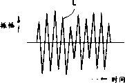
Shown in Figure 1A~1H be these methods to the stereophonic signal coding of routine, decoding and playback the time produce the state of quantizing noise.
This Figure 1A, 1B represent the time shaft waveform of stereophonic signal L channel composition (L) and stereophonic signal R channel composition (R) respectively, Fig. 1 C, 1D represent that respectively L, R sound channel composition are transformed to the time shaft waveform of (L+R)/2, (L-R)/2 signal through sound channel, represent (L+R)/2, (L-R)/2 with A, B respectively among Fig. 1 C, the 1D.Usually, have stronger correlation between each sound channel of stereophonic signal, thereby B=(L-R)/2 compares with original signal L or R, its signal level is quite little.
Fig. 1 E, 1F illustrate the state that produces quantizing noise when utilizing above-mentioned high efficient coding method respectively to above-mentioned (L+R)/2=A, (L-R)/2=B signal encoding and decoding, the time shaft waveform of the quantizing noise composition that is produced when N1 and N2 represent (L+R)/2=A, (L-R)/2=B signal encoding respectively among the figure.Here, (L+R)/the encoded decoded signal of 2=A signal, the encoded decoded signal of (L-R)/2=B signal can represent with A+N1, B+N2 respectively.Quantization noise level depends on original signal level mostly in the high efficient coding method, this occasion, and the N2 signal level is compared with the N1 signal level, and is just quite little.
Fig. 1 G, 1H illustrate the state of isolating each sound channel of stereophonic signal in the middle of (A+N1), (B+N2) signal waveform.By making (A+N1) and (B+N2) signal plus, but cancellation R sound channel composition only takes out the L composition, and by deducting (B+N2) signal in the middle of (A+N1), but cancellation L sound channel composition only takes out R sound channel composition.
Quantizing noise composition N1 and N2 with (N1+N2) or (N1-N2) form keep, but that the N2 level is compared with N1 is minimum, thereby is not a problem especially aspect the sense of hearing.
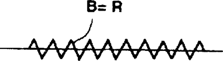
Fig. 2 A, 2H then illustrate and compare very little stereophonic signal with R channel (R) signal level with L channel (L) signal level is the state that example produces quantizing noise equally.Fig. 2 A, 2B represent the time shaft waveform of stereophonic signal L channel composition (L) and stereophonic signal R channel composition (R) respectively, and Fig. 2 C, 2D represent that respectively L, R sound channel composition are transformed to the time shaft waveform of (L+R)/2, (L-R)/2 signal through sound channel.Also identical among this Fig. 2 C, 2D with Fig. 1 example, represent (L+R)/2, (L-R)/2 with A, B respectively.In this example, R sound channel composition signal level is little, and is not relevant between two sound channels, thereby B=(L-R)/2 signal level is not little, but near the signal of A=(L+R)/2.
Fig. 2 E, 2F are also identical with Fig. 1, the state that produces quantizing noise when utilizing above-mentioned high efficient coding method respectively to above-mentioned (L+R)/2=A, (L-R)/2=B signal encoding and decoding is shown, the time shaft waveform of the quantizing noise composition that is produced when N1 and N2 represent (L+R)/2=A, (L-R)/2=B signal encoding respectively among the figure.Here identical with Fig. 1 example, (L+R)/the encoded decoded signal of 2=A, the encoded decoded signal of (L-R)/2=B can represent with A+N1, B+N2 respectively.
Fig. 2 G, 2H are also identical with Fig. 1, and the state of isolating each sound channel of stereophonic signal in the middle of (A+N1), (B+N2) signal waveform is shown.By making (A+N1) and (B+N2) signal plus, but cancellation R sound channel composition only takes out the L composition, and by in the middle of (A+N1), deducting (B+N2) signal, but cancellation L sound channel composition only takes out R sound channel composition.
In this occasion of Fig. 2 example, quantizing noise composition N1 and N2 are with (N1+N2) or (N1-N2) form reservation, but R sound channel composition signal level is very little in should example, thereby can't shelter (N1-N2) quantizing noise composition with R sound channel composition, sometimes at R sound channel one quantizing noise of eavesdropping.
Summary of the invention
Therefore, the present invention In view of the foregoing, its purpose be to provide a kind of can be by adapting to the playback of old standard playback reproducer, simultaneously carrying out the new criteria expansion when realizing the coding and decoding of multichannel, the quantizing noise that coding can be produced suppresses to be Min., alleviates coding method and device, decoding device and the recording medium of both poor sound quality.
Specifically, the present invention can be by for example adapting to the playback of old standard playback reproducer institute, simultaneously in the middle of the coding-decoding method of expansion new criteria with the realization multichannel, by select the sound channel signal of expansion best according to input signal, the quantizing noise that coding is produced suppresses to alleviate both poor sound quality for Min..
Coding method of the present invention, signal by the multichannel aqueduct generates first signal, obtain the signal level of part aqueduct and other aqueducts in the multichannel aqueduct, according to signal level, only select any one in the middle of the secondary signal that the secondary signal is made up of part aqueduct signal and multichannel aqueduct signal generate, first signal and selected secondary signal are encoded.
Code device of the present invention comprises: first signal generation means that is generated first signal by the signal of multichannel aqueduct; According to the signal level of part aqueduct in the multichannel aqueduct and other aqueducts, only select any one the secondary signal generation means in the middle of the secondary signal that the secondary signal is made up of part aqueduct signal and multichannel aqueduct signal generate; With the coding means that first signal and selected secondary signal are encoded.
Coding/decoding method of the present invention, separate first code signal, second code signal in the middle of the coded sequence and show road signal that second code signal constituted that it constitutes the configuration information of state, first and second code signals decoding to separating respectively, generate first and second signals, according to configuration information, select to handle in order to the reduction that generates the multiple tracks signal from first and second signals.
Coding/decoding method of the present invention, from comprise the multiple tracks signal through generating coding first code signal and second code signal of selecting some codings in the middle of the secondary signal of the secondary signal only formed and the generation of multiple tracks signal according to multiple tracks shunting, middle part and other road signal levels by part road signal in the middle of interior coded sequence, separate first code signal and second code signal, respectively to separated first and second code signals decoding, according to first and second signals reduction multiple tracks signal through decoding.
Decoding device of the present invention comprises: separate first code signal, second code signal in the middle of the coded sequence and show the separation means of configuration information of the formation state of the road signal that second code signal is constituted; Respectively separated first and second code signals are decoded, and generate the decoding means of first and second signals; With according to configuration information, select the control device of handling in order to the reduction that generates the multiple tracks signal from first and second signals.
Decoding device of the present invention comprises: from comprise the multiple tracks signal through generating coding first code signal and select in the middle of the coded sequence of second code signal of some codings in the middle of the secondary signal of the secondary signal only formed and the generation of multiple tracks signal the separation means of separating first and second code signals by part road signal according to multiple tracks shunting, middle part and other road signal levels; Respectively to the decoding means of separated first and second code signals decoding; With reduction means according to the reduction of first and second signals through decoding multiple tracks signal.
First aspect present invention be used for coding method to signal encoding, it is characterized in that, comprise the following steps:
Generate first audio signal by the stereo channels that comprises in the multichannel input sound channel, it is corresponding that wherein the R channel and of this stereo channels and with an acoustic signal has the L channel of another acoustic signal;
Determine one with R channel and the L channel corresponding signal level of wherein a certain sound channel and R channel and L channel another signal level of another sound channel wherein;
Select one second audio signal according to each signal level, thereby in the middle of R channel, L channel and one deduct the signal different with described first audio signal that R channel generates by L channel, select one second audio signal;
To described first coding audio signal;
By first coding techniques to the second selected coding audio signal; And
Show one by second coding techniques signal of the selection of described second audio signal is encoded;
Wherein, described first coding techniques is different with described second coding techniques.
Second aspect present invention be used for code device to signal encoding, it is characterized in that, comprising:
First signal generating apparatus is used for generating first audio signal by the stereo channels that the multichannel input sound channel comprises, it is corresponding that wherein the R channel and of this stereo channels and with an acoustic signal has the L channel of another acoustic signal;
The secondary signal generating apparatus, be used for determining one with R channel and the L channel corresponding signal level of wherein a certain sound channel and R channel and L channel another signal level of another sound channel wherein, and select one second audio signal, thereby in the middle of deducting the signal different with described first audio signal that R channel generates by L channel, R channel, L channel and one select one second audio signal according to each signal level; And
Coding unit is used for described first audio signal, described selected second audio signal, and one shows the signal of the selection of described second audio signal is encoded,
Wherein, by first coding techniques to described first coding audio signal, and by second coding techniques different with described first coding techniques to the described second selected coding audio signal.
Third aspect present invention be used for coding/decoding method to decoding through encoded signals, it is characterized in that, comprise the following steps:
Separate first code signal, second code signal in the middle of the coded sequence and show second its formation of code signal sound channel signal its constitute the configuration information of state;
Respectively first and second code signals of described separation are decoded, generate first and second signals, wherein first code signal of described separation is decoded and generate one first signal, generate a secondary signal and described second code signal that separates is decoded by second decoding technique different with described first decoding technique by first decoding technique; And
According to described configuration information, select to handle in order to the reduction that generates a plurality of sound channel signals from described first and second signals.
Fourth aspect present invention be used for coding/decoding method to decoding through encoded signals, it is characterized in that, comprise the following steps:
With one first code signal, one second code signal, with a signal that shows the selection of described second code signal, comprise described first code signal from one, described second code signal, show that with described signal to the selection of described second code signal separates in the middle of interior coded sequence, described first code signal is generated by the stereo channels that a plurality of sound channels comprise, it is corresponding that the R channel and that described stereo channels and has an acoustic signal has the L channel of another acoustic signal, described second code signal be according to the signal level of the signal level of described R channel and described L channel and chosen and the coding, thereby from described R channel, described L channel, and one select described second code signal in the middle of deducting the signal different with described first code signal that described R channel generates by described L channel;
Respectively to first code signal of described separation, second code signal, and described showing the signal of the selection of described second code signal is decoded, wherein, by first decoding technique first code signal of described separation is decoded, and described second code signal is decoded by second decoding technique different with described first decoding technique; And
Reduce the corresponding output signal of each sound channel in described a plurality of sound channel according to described first and second code signals through decoding.
Fifth aspect present invention be used for decoding device to decoding through encoded signals, it is characterized in that, comprising:
Separator, it constitutes the configuration information of state to be used for the sound channel signal that separates first code signal, second code signal in the middle of the coded sequence and show second its formation of code signal;
Decoding unit, be used for respectively first and second code signals of described separation being decoded, generate first and second signals, wherein first code signal of described separation is decoded and generate one first signal, generate a secondary signal and described second code signal that separates is decoded by second decoding technique different with described first decoding technique by first decoding technique; And
Control device is used for according to described configuration information, selects to handle in order to the reduction that generates a plurality of sound channel signals from described first and second signals.
Sixth aspect present invention be used for decoding device to decoding through encoded signals, it is characterized in that, comprising:
Separator, be used for one first code signal, one second code signal, with a signal that shows the selection of described second code signal, comprise described first code signal from one, described second code signal, show that with described signal to the selection of described second code signal separates in the middle of interior coded sequence, described first code signal is generated by the stereo channels that a plurality of sound channels comprise, it is corresponding that the R channel and that described stereo channels and has an acoustic signal has the L channel of another acoustic signal, described second code signal be according to the signal level of the signal level of described R channel and described L channel and chosen and the coding, thereby from described R channel, described L channel, and one select described second code signal in the middle of deducting the signal different with described first code signal that described R channel generates by described L channel;
Decoding unit, be used for respectively to described separation first code signal, second code signal, and described showing the signal of the selection of described second code signal is decoded, wherein, by first decoding technique first code signal of described separation is decoded, and described second code signal is decoded by second decoding technique different with described first decoding technique; And
Reduction apparatus is used for reducing the corresponding output signal of described a plurality of each sound channel of sound channel according to described first and second code signals through decoding.
Description of drawings
Figure 1A~1H is that prior art produces the key diagram that quantizes noise states when the normal stereo signal is carried out Code And Decode and playback.
Fig. 2 A~2H produces the key diagram that quantizes noise states when to be prior art to R channel (R) signal level and L channel (L) signal level compare very little stereophonic signal and carry out Code And Decode and playback.
Fig. 3 is the circuit block diagram of signal as the record playback reproducer configuration example of packed data record playback reproducer one embodiment of the present invention.
Fig. 4 is the circuit block diagram of the concrete configuration example of signal code device.
Fig. 5 is the circuit block diagram of the concrete configuration example of signal translation circuit.
Fig. 6 is the circuit block diagram of the concrete configuration example of aid composition coding circuit.
Fig. 7 is the circuit block diagram of the concrete configuration example of signal decoding device.
Fig. 8 is the circuit block diagram of the concrete configuration example of signal inverse transform circuit.
Fig. 9 is the circuit block diagram of the concrete configuration example of aid composition decoding circuit.
Figure 10 is the key diagram of basic coding method.
Figure 11 is the key diagram by its coded sequence formation of frame of basic coding method coding.
Shown in Figure 12 is the example of each frame configuration L, R sound channel.
Shown in Figure 13 is the example that disposes (L+R)/2 sound channel frame by frame.
Figure 14 is the key diagram that is divided into the coding method that tonal content and noise contribution encode to signal component.
Figure 15 is the key diagram that constitutes by its coded sequence of frame that is divided into the coding method coding that tonal content and noise contribution encode to signal component.
Figure 16 is divided into tonal content and noise contribution carry out the concrete configuration example of encoded signals composition coding circuit to signal component circuit block diagram.
Figure 17 is the circuit block diagram that signal component is divided into the concrete configuration example of signal component decoding circuit that tonal content and noise contribution encoded signals decode.
The key diagram of record format when Figure 18 is the coded sequence of record A coding and decoding method.
The key diagram of record format when Figure 19 is the coded sequence of record A coding and decoding method and B coding and decoding method.
Figure 20 is the key diagram that can avoid adapting to the record format of old standard playback reproducer mistake playback B coding and decoding method when having write down the coded sequence of A coding and decoding method and B coding and decoding method.
Figure 21 is the key diagram that disposes its formation of coded sequence of A coding and decoding method and B coding and decoding method signal in the frame.
Figure 22 is the concrete circuit block diagram that constitutes of code device that disposes the coded sequence of A coding and decoding method and B coding and decoding method signal in the signal delta frame.
Figure 23 is that the code device that disposes the coded sequence of A coding and decoding method and B coding and decoding method signal in the signal delta frame is handled routine flow chart.
Figure 24 is the concrete circuit block diagram that constitutes of signal component decoding device that signal is decoded to the coded sequence of configuration A coding and decoding method and B coding and decoding method signal in the frame.
Figure 25 is that the signal component decoding device that signal is decoded to the coded sequence of configuration A coding and decoding method and B coding and decoding method signal in the frame is handled routine flow chart.
Figure 26 is the key diagram that disposes the coded sequence formation of sound channel composition data and A sound channel and B sound channel signal in the embodiment of the invention frame.
Figure 27 is the concrete circuit block diagram that constitutes of code device that disposes the coded sequence of sound channel composition data and A sound channel and B sound channel signal in the signal embodiment of the invention delta frame.
Figure 28 is the flow chart of its handling process of control circuit of the signal embodiment of the invention code device that generates coded sequence.
Figure 29 is that the code device that disposes the coded sequence of sound channel composition data and A sound channel and B sound channel signal in the signal embodiment of the invention delta frame is handled routine flow chart.
Figure 30 is the concrete circuit block diagram that constitutes of code device that the signal embodiment of the invention is decoded to the coded sequence of configuration sound channel composition data and A sound channel and B sound channel signal in the frame.
Figure 31 is the flow chart of the signal embodiment of the invention its handling process of decoding device that coded sequence is decoded.
Figure 32 is the flow chart that the signal embodiment of the invention decoding device that coded sequence is decoded is determined the handling process of decoding process.
Figure 33 A~33H produces the key diagram that quantizes noise states when to be the embodiment of the invention to R channel (R) signal level and L channel (L) signal level compare very little stereophonic signal and carry out Code And Decode and playback.
Embodiment
Following with reference to the description of drawings specific embodiment of the invention.At first, Fig. 3 illustrates the summary formation of the packed data record and/or the playback reproducer of application one embodiment of the invention.
In the packed data record and/or playback reproducer shown in Figure 3, the magneto optical disk 1 that utilizes spindle drive motor (M) 51 rotation drivings earlier is as recording medium.When magneto optical disk 1 is carried out data record, under the state of for example optical head (H) 53 irradiating lasers, add the modulated magnetic field corresponding, carry out so-called magnetic field modulation record, along magneto optical disk 1 record rail record data with record data by magnetic head 54.And during playback, by laser magneto optical disk 1 record rail is carried out tracking by optical head 53, carry out playback in the magnetooptics mode.
Optical head 53 is made of opticses such as LASER Light Source such as for example laser diode, collimating lens, object lens, polarizing beam splitter, cylinder lenses and optical detector with prescribed model photographic department etc.This optical head 53 is arranged on the position relative with magnetic head 54 by magneto optical disk 1.With data record when the magneto optical disk 1, magnetic head drive circuit 66 driving magnetic heads 54 by the record system that addresses later add the modulated magnetic field corresponding with record data, and by optical head 53 with laser radiation in magneto optical disk 1 purpose rail, thereby carry out thermo magnetic recording by the magnetic field modulation mode.And this optical head 53 detects the reverberation that shines in the laser of purpose rail, detects focusing error by for example so-called astigmatism method, detects tracking error by for example what is called method of recommending.During by magneto optical disk 1 playback of data, when optical head 53 detects above-mentioned focusing error or tracking error, detect the difference of laser, generate playback signal from the polarization of reflected light angle (crossing the anglec of rotation) of purpose rail.
The output of optical head 53 offers RF circuit 55.This RF circuit 55 extracts above-mentioned focus error signal or tracking error signal in the middle of optical head 53 outputs, offer servo control circuit 56, and make playback signal 2 values, offers the decoder 71 of aftermentioned playback system.
Servo control circuit 56 is made of for example focus servo control circuit, tracking servo control circuit, spindle drive motor servo control circuit and helical servo control circuit etc.Above-mentioned focus servo control circuit carries out focus control to the optical system of optical head 53, so that above-mentioned focus error signal is zero.And above-mentioned tracking servo control circuit carries out tracking control to the optical system of optical head 53, so that above-mentioned tracking error signal is zero.Above-mentioned spindle drive motor servo control circuit is controlled spindle drive motor 51 so that rotary speed (for example constant linear velocity) rotation drives magneto optical disk 1 in accordance with regulations.And above-mentioned helical servo control circuit makes optical head 53 and magnetic head 54 move to the purpose rail position of the magneto optical disk 1 of system controller 57 appointments.The servo control circuit 56 that carries out various like this control actions will show that the information of the operating state of the various piece that this servo control circuit 56 is controlled delivers to system controller 57.
System controller 57 is connected with key input operation part 58 and display part (display) 59.This system controller 57 is controlled record system and playback system according to the operation input information of key input operation part 58.System controller 57 is according to the address information of magneto optical disk 1 record rail by the sector unit of the playback such as Q data of stem time or subcode, record position or playback position on the above-mentioned record rail of management optical head 53 and 54 trackings of magnetic head.System controller 57 is controlled according to the data compression rate of this packed data record playback reproducer and the playback location information on the above-mentioned record rail, makes display part 59 show playback duration.
The demonstration of this playback duration, be to the address information (absolute time information) of magneto optical disk 1 record rail by the sector unit of playback such as so-called stem time or so-called subcode Q data, multiply by inverse when compression (for example 1/4 be 4) of data compression rate, the temporal information on realistic border, and on display part 59, show it.In addition, during record, for example when record rails such as magneto optical disk record absolute time information (preformatting) in advance, also can be by reading the absolute time information of this preformatting, multiply by the inverse of data compression rate, with physical record time showing current location.
Next, the record of this disc record playback reproducer system offers A/D converter 62 by low pass filter (LPF) 61 with the analogue audio frequency input signal Ain of input terminal 60, and 62 couples of above-mentioned analogue audio frequency input signal Ain of this A/D converter quantize.The digital audio and video signals that obtains from A/D converter 62 offers ATC, and (Adaptive Trausform Coding: Adaptive Transform Coding) encoder 63.And the digital audio input signal Din of input terminal 67 offers ATC encoder 63 by digital input interface circuit (numeral input) 68.ATC encoder 63 is to the digital audio PCM data of above-mentioned input signal Ain through the regulation transfer rate of A/D converter quantification, data compression rate carries out the device that position compression (data compression) is handled according to the rules, and the packed data (ATC data) of ATC encoder 63 outputs offers memory 64.Be that 1/8 occasion is illustrated with regard to data compression rate for example, the data transfer rate here can be reduced to 1/8 (i.e. 9.375 sector/seconds) of the data transfer rate (75 sector/second) of the CD-DA form of above-mentioned standard.
Next, memory 64 being write and being read by system controller 57 control datas, and as buffer, temporarily stores the ATC data that ATC encoder 63 provides, and is recorded on the disc as required.Specifically, for example data compression rate is 1/8 o'clock, its data transfer rate of the audio compressed data that ATC encoder 63 provides be reduced to the CD-DA form of standard data transfer rate (75 sector/second) 1/8, i.e. 9.374 sector/seconds, the continuous write memory 64 of this packed data.The record that this packed data (ATC data), per as mentioned before 8 sectors carry out 1 sector is just enough, but this record every 8 sectors is in fact impossible, thereby manages to carry out described sector, back recording occurring continuously.This record accompanies stopping period by the centre, with a plurality of sectors (for example 32 sector+several sectors) of regulation formed bunch as writing down unit, carry out to bursting property with the data transfer rate identical (75 sector/second) with the CD-DA form of standard.
Specifically, the ATC voice data of the data compression rate 1/8 that writes continuously with the low transmission speed of 9.375 (=75/8) sector/second corresponding in the memory 64 with last rheme compression ratio, by above-mentioned 75 sectors/second bursting property of transfer rate read as record data.For this data of reading and writing down, comprising the conceptual data transfer rate that writes down stopping period is the low velocity of above-mentioned 9.375 sector/seconds, but the transient data transfer rate of the operation of recording time that bursting property is carried out is 75 sector/seconds of above-mentioned standard.Thereby, when the disc rotary speed is the speed (constant linear velocity) identical with the CD-DA form of standard, carry out the packing density identical and the record of memory module with this CD-DA form.
With above-mentioned 75 sector/second (instantaneous) transfer rate from memory 64 bursting property the ATC voice data read, promptly record data offer encoder 65.Here, offered by memory 64 in the data sequence of encoder 65, once continuous recording unit is made as that a plurality of sectors (for example 32 sectors) form in the middle of the record bunch and several sectors that bunch are connected usefulness that are disposed at this bunch front and back position.This bunch connection must be longer than the weaving length in the encoder 65 with sector settings, brings influence also can for the data of other bunches even if having to interweave.
65 pairs of memory 64 bursting property as indicated above of encoder the record data that provide carry out the encoding process (adding that parity check sum carries out interleaving treatment) of error correction purposes and EFM encoding process etc.Record data through these encoder 65 encoding process offer magnetic head drive circuit 66.This magnetic head drive circuit 66 is connected with magnetic head 54, and drives magnetic head 54, so that the modulated magnetic field corresponding with above-mentioned record data is added on the magneto optical disk 1.
And 57 pairs of memories of system controller 64 carry out aforesaid storage control, by storage control record position are controlled simultaneously, write down rail so that the above-mentioned record data of reading from memory 64 bursting property ground are recorded in magneto optical disk 1 continuously.The record position of the above-mentioned record data of being read from memory 64 bursting property ground by system controller 57 management offers the record position of servo control circuit 56 to specify magneto optical disk 1 to write down on the rail with control signal, realizes the control of this record position.
Below the explanation playback is, this playback system is the part that ties up to continuous recording record data on the magneto optical disk 1 record rail in order to the above-mentioned record of playback, has the decoder 71 that provides after RF circuit 55 binaryzations by the playback output that optical head 53 usefulness laser are obtained the record rail tracking of magneto optical disk 1.At this moment be not only magneto optical disk, also can read and the identical playback special-purpose cd of so-called CD (CD:Compact Disc trade mark).
Decoder 71 is devices corresponding with encoder 65 in the described record system, playback output with regard to RF circuit 55 binaryzations, carry out processing such as aforesaid decoding processing that error correction uses or EFM decoding processing, and by the ATC voice data of the 75 sectors/second transfer rate playback above-mentioned data compression rate 1/8 faster than normal transfer rate.The playback of data that this decoder 71 obtains offers memory 72.
Memory 72 being write and being read by system controller 57 control datas, decoder 71 by playback of data that 75 sector/seconds, transfer rate provided with this 75 sector/second bursting property of transfer rate write.And this memory 72 by above-mentioned 75 sectors/second bursting property of transfer rate the above-mentioned playback of data that writes read continuously by 9.375 sectors of data compression rate 1/8 correspondence/second transfer rate.
System controller 57 is stored control, writes playback of data with 75 sectors/second transfer rate to memory 72, and reads above-mentioned playback of data from memory 72 continuously with 9.375 sectors/second transfer rate.And system controller 57 is controlled playback position by storage control when memory 72 is stored control as mentioned above, so as from continuous playback memory 72 the bursting property of magneto optical disk 1 record rail the described playback of data that writes.By system controller 57 management from memory 72 bursting property the playback position of the above-mentioned playback of data read, provide control signal to servo control circuit 56, to specify the playback position on magneto optical disk 1 or the magneto optical disk 1 record rail, realize the control of this playback position.
The ATC voice data that obtains as playback of data by 9.375 sectors/second transfer rate is read from memory 72 continuously offers ATC decoder 73.This ATC decoder 73 is devices corresponding with ATC encoder 63 in the record system, for example reaches 8 times by the ATC data being carried out data expansion (position expansion), comes playback 16 bit digital voice datas.The digital audio-frequency data of these ATC decoder 73 outputs offers D/A converter 74.
D/A converter 74 is transformed to analog signal with the digital audio-frequency data that ATC decoder 73 provides, and forms analogue audio frequency output signal Aout.The simulated audio signal Aout that this D/A converter 74 obtains is by low pass filter (LPF) 75, by lead-out terminal 76 outputs.
Next describe the high-frequency compressed encoding in detail.Specifically, the description of drawings that rises with reference to Fig. 4 utilizes subband coding (SBC), Adaptive Transform Coding (ATC) and adaptive bit to distribute every technology supplied with digital signal such as audio frequency PCM signal to be carried out the technology of high efficient coding.
The code device (encoder 63 among Fig. 3) of carrying out sound equipment waveform signal of the present invention coding method as shown in Figure 4, by translation circuit 111a the signal waveform 110a that is imported is transformed to signal frequency composition 110b, resulting each frequency content 110b is through signal component coding circuit 111b coding, and the code signal 110c that generates according to signal component coding circuit 111b in coded sequence generative circuit 111c generates coded sequence 110d then.
And among the translation circuit 111a as shown in Figure 5,112a is segmented into 2 frequency bands with input signal 120a by frequency band segmentation filter, by the spectrum transformation circuit 112b, the 112c that adopt MDCT etc. signal 120b, the 120c of resulting 2 frequency bands is transformed to spectrum signal composition 120d, 120e.In addition, input signal 120a is corresponding with Fig. 4 signal waveform 110a, and spectrum signal composition 120d, 120e are then corresponding with Fig. 4 signal frequency composition 110b.Have among the translation circuit 111a of this formation shown in Figure 5, the bandwidth that is segmented into signal 120b, the 120c of above-mentioned 2 frequency bands is 1/2 of an input signal 120a bandwidth, and by this input signal of 1/2 interpolation 120a.Certainly, except that this concrete example, this translation circuit 111a also has multiple scheme, and for example directly or to utilize MDCT that input signal is transformed to spectrum signal good, without MDCT, and it is good to utilize DFT or DCT to carry out conversion.And, although utilize so-called frequency band segmentation filter also signal subsection can be band component, coding method of the present invention is fit to adopt many frequency contents to try to achieve and to utilize above-mentioned spectrum transformation input signal to be transformed to the method for frequency content by less relatively operand.
Signal component coding circuit 111b as shown in Figure 6, make each signal component 130a normalization by normalization circuit 113a by each allocated frequency band, and determine that by quantified precision circuit 113b calculate to quantize precision information 130c according to signal component 130a, sample circuit 113c is according to this quantified precision information 130c, and the normalized signal 130b that normalization circuit 113a is exported quantizes.In addition, each signal component 130a is corresponding to Fig. 4 signal frequency composition 110b, and the output signal 130d of sample circuit 113c is corresponding to Fig. 4 code signal 110c.Wherein this output signal 130d is except the signal component through quantizing, normalization coefficient information or above-mentioned quantified precision information when also comprising above-mentioned normalization.
In the decoding device (decoder 73 in Fig. 3 example) of the coded sequence reconstructed audio signals that generates according to code device as mentioned above, then as shown in Figure 7, extract the coding 140b of each signal component in the middle of the coded sequence 140a by coded sequence decomposition circuit 114a, these codings 140b is reduced to each signal component 140c by signal component decoding circuit 114b, like this through the signal component 140c of reduction, rebuild sound equipment waveform signal 140d by inverse transform circuit 114c basis.
The inverse transform circuit 114c of this decoding device constitutes as shown in Figure 8, is the device corresponding with translation circuit shown in Figure 5.Among this inverse transform circuit 114c shown in Figure 8, contrary spectrum transformation circuit 115a, 115b carry out contrary spectrum transformation to input signal 150a, the 150b that provides respectively, reduce each band signal, and by synthetic these band signals of band synthesis filter 115c.Input signal 150a, 150b are corresponding to the signal 140c that each signal component reduction obtains with Fig. 7 signal component decoding circuit 114b.And the output signal 150e of band synthesis filter 115c is corresponding with Fig. 7 sound equipment waveform signal 140d.
Fig. 7 signal component decoding circuit 114b constitutes as shown in Figure 9, and the coding 140b that Fig. 7 coded sequence decomposition circuit 114a is exported is a spectrum signal, carries out re-quantization and contrary normalized.Among this signal component decoding circuit 114b shown in Figure 9, by inverse quantization circuit 116a the coding 160a that is imported is carried out re-quantization, the signal 160b that above-mentioned re-quantization is obtained by contrary normalization circuit 116b carries out contrary normalization, output signal composition 160c.Coding 160a is corresponding to the coding 140b of Fig. 7 coded sequence decomposition circuit 114a output, and output signal composition 160c is corresponding to Fig. 7 signal component 140c.
In addition, the spectrum signal that translation circuit shown in Figure 5 obtains in the code device as mentioned above, for example as shown in figure 10.This each spectrum component shown in Figure 10 is that [dB] illustrates the absolute value based on the spectrum component of MDCT with level translation.Specifically, this signal coding equipment is transformed to 64 spectrum signals by each regulation transform block with input signal, gather for [1] among the figure to 8 frequency bands (hereinafter referred to as coding unit) shown in [8], this is carried out normalization and quantification.If each above-mentioned transform block makes quantified precision variation this moment with the distribution pattern of frequency content, can realize that just the both poor sound quality inhibition is a bottom line, the high coding of efficient aspect the sense of hearing.
Below, the configuration example of coded sequence when Figure 11 illustrates and encodes with said method.
The coded sequence of this configuration example disposes in order to reduce the data of each transform block spectrum signal, encoded information with the corresponding configuration of frame that constitutes by the regulation figure place respectively, the stem of each frame (ヘ Star グ portion) disposes: figure place was carried out information encoded to synchronizing signal and encoded control datas such as coding unit number in accordance with regulations before this, next being that coding unit by low-frequency range one side carries out information encoded to each coding unit quantified precision data and normalization coefficient data respectively, is by each coding unit the spectral coefficient data of finishing normalization and quantification according to above-mentioned normalization coefficient data and quantified precision data to be carried out information encoded from low-frequency range one side at last.
In order to reduce the spectrum signal of this transform block, actual required figure place determines that by the quantization digit that above-mentioned coded coding unit and each coding unit quantified precision information provide each frame difference of this numerical value is good.It is meaningful when the playback to play only above-mentioned required figure place with each frame stem, and the zone of each frame remainder is idle zone, can not bring influence to playback signal.Usually,, manage effectively to utilize more position, make each frame idle area as far as possible little in order to improve tonequality.
So shown in the example, by making the corresponding coding of frame of each transform block and a location number, when being recorded in recording mediums such as CD in the example of for example should encoding, can easily calculate the record position of any transform block, thereby can carry out playback from the optional position, be convenient to realize so-called arbitrary access.
Below, the routine record format when Figure 12 and Figure 13 illustrate data with frame shown in Figure 11 and be disposed at recording medium etc. by for example time series.Figure 12 illustrates for example example of each frame alternate configurations L (left side), these 2 sound channel signals of R (right side), and Figure 13 then illustrates the example that each these 2 sound channel signal of frame configuration L, R generates 1 sound channel signal (by the monophonic signal of these 2 sound channel signals generations of L, R) of (L+R)/2.
By adopting these record format as shown in figure 12, but signal to identical recordings media recording L, these 2 sound channels of R, and as shown in figure 13, when adopting each frame only to dispose the record format of above-mentioned (L+R)/2 one sound channel, compare with the record format of each frame alternate configurations L shown in Figure 12, two sound channels of R, can write down playback to the signal of DT Doubling Time, but also playback easily avoids playback circuitry to become complicated.
In addition, if record format shown in Figure 12 is called for example standard time mode, then can be described as the long-time mode that can write down the mode multiple time above-mentioned standard time of playback with the record format of the long-time signal of less channel number record playback as shown in figure 13.And, even if Figure 12 example, for each frame recording be a this sound channel of monophony, and two sound channels of L, R, the signal of DT Doubling Time carries out record in the time of just can be to two sound channels of record L, R, also can be called long-time mode this moment.
In the above-mentioned explanation, only just the technology of Figure 11 explanation is illustrated as coding method, but to the coding method that this Figure 11 illustrates, also can further improve code efficiency.
For example, can adopt so-called variable-length encoding technology, promptly in the middle of spectrum signal, high to the frequency of occurrences through quantizing, distribute longly than short code relatively, low to the frequency of occurrences, then distribution is long than long code relatively, improves code efficiency.
And, if manage to make the afore mentioned rules transform block (time block that spectrum transformation is used) when for example input signal being encoded to prolong, just can reduce quantified precision information and this seed information content of normalization coefficient information of each piece relatively, and frequency resolution also improves, thereby the quantified precision on the control frequency axle more subtly, can improve code efficiency.
In addition, international open WO94/28633 specification of this case applicant's PCT application and accompanying drawing propose a kind of method, in the middle of the spectrum signal composition, be separated in acoustically tonality signal component and other spectrum signal compositions of particular importance, encode respectively, utilize the method just can produce distortion acoustically hardly by higher compression ratio effectively to audio-frequency signal coding.
Here, illustrate that with Figure 14 separating above-mentioned tonality signal component carries out Methods for Coding.In this Figure 14 example, what illustrate is the state that will gather respectively in the middle of the spectrum signal composition for 3 tonal contents separation of tonality signal component, and each signal component that constitutes these tonal contents is encoded with the position data separately of each tonal content on frequency axis.
Usually, for fear of both poor sound quality, need be with very high accuracy quantification concentration of energy each signal component in the above-mentioned tonal content of minority frequency spectrum, the interior spectral coefficient (non-pitch spectrum signal composition) of each coding unit can quantize by less relatively exponent number after isolating tonal content, and tonequality can variation on the sense of hearing.
Among Figure 14 for simplicity, only illustrate less relatively spectrum signal composition, in the actual tone composition, concentration of energy several signal components in the coding unit that tens spectrum signal compositions constitute, thereby the increase of the data volume that separation caused of this tonal content is less relatively, can improve code efficiency generally by separating these tonal contents.
The configuration example of coded sequence when following Figure 15 illustrates with the method coding of Figure 14 explanation.In this configuration example, each frame start-up portion disposes by the regulation figure place as stem synchronizing signal and coded control datas such as coding unit number is carried out information encoded, and the data (being the tonal content data) that next dispose with regard to relevant tonal content are carried out information encoded.
As the tonal content data, initial configuration has in pair tonal content each signal component number carry out information encoded, next configuration respectively to the positional information of each tonal content on frequency axis, then be in the tonal content quantified precision data, normalization coefficient data, carry out information encoded through the tonality signal component (spectral coefficient data) of normalization and quantification etc.
After above-mentioned tonal content data, dispose the encoded information of residual signal (also can be called the noise-induced signal component) its data that deducts above-mentioned tonality signal component from original spectrum signal composition.Here dispose respectively from low-frequency range one side coding unit each coding unit quantified precision data and normalization coefficient data, and each coding unit is finished normalization according to above-mentioned normalization coefficient data and quantified precision data and the spectral coefficient that quantizes carries out information encoded according to (signal component beyond the tonal content).What wherein, suppose that the spectrum signal composition (coefficient data) of tonality and signal component in addition carries out is variable-length encoding.
Figure 16 illustrates the concrete example of Fig. 4 signal component coding circuit 111b when separating the tonality signal component in the middle of above-mentioned each signal component.
Among this signal composition coding circuit 111b shown in Figure 16, the signal component 170a (110b) that Fig. 4 translation circuit 111a provides delivers to tonal content split circuit 117a.Signal component 170a is divided into tonality signal component and signal component in addition (non-pitch signal component), tonality signal component 170b delivers to tonal content coding circuit 117b, and non-pitch signal component 170c delivers to non-pitch composition coding circuit 117c.After these tonal content coding circuit 117b and non-pitch composition coding circuit 117c encode to the signal component that provides respectively, output signal 170d and 170e that output obtains respectively.In addition, when tonal content coding circuit 117b encodes to above-mentioned tonality signal component, also carry out the generation of the various configuration informations of Figure 15 tonal content data.The used formation of signal encoding is identical with Fig. 6 respectively among tonal content coding circuit 117b and the non-pitch composition coding circuit 117c.
Figure 17 illustrates the concrete example of Fig. 7 signal component decoding circuit 114b when separating the tonality signal component in the middle of above-mentioned each signal component.
Among this signal component decoding circuit 114b shown in Figure 17, the coding 140b that Fig. 7 coded sequence decomposition circuit 114a provides is made up of above-mentioned tonal content data 180a and non-pitch signal component 180b, and these data and signal component are delivered to corresponding respectively tonal content decoding circuit 118a and non-pitch composition decoding circuit 118b.Above-mentioned tonal content decoding circuit 118a decodes to the tonality signal component according to tonal content data shown in Figure 15, and exports resulting tonality signal component 180c.And above-mentioned non-pitch composition decoding circuit 118b exports resulting non-pitch signal component 180d to the decoding of non-pitch signal component.These tonality signal component 180c and nonlinear properties composition 180d all deliver to spectrum signal combiner circuit 118c.This spectrum signal combiner circuit 118c according to synthetic above-mentioned tonality signal component of above-mentioned position data and non-pitch signal component, exports resulting signal component 180e.In addition, the used formation of signal decoding is identical with Fig. 9 respectively among tonal content decoding circuit 118a and the non-pitch composition decoding circuit 118b.
Form example when here, Figure 18 illustrates encoded signals as mentioned above is recorded in magneto optical disk for example.In addition, in this Figure 18 example, suppose to record for example 4 cover (4 song) audio signal datas altogether.
Among this Figure 18, except above-mentioned 4 cover audio signal datas altogether, this CD also records management data used when writing down this audio signal data of playback.No. 0 address in management data district, No. 1 address record initial data sequence number, end data sequence number respectively.In Figure 18 example, record 1 value, record 4 values as the end data sequence number as above-mentioned initial data sequence.Hence one can see that, this disc record have the 1st to the 4th totally 4 the cover audio signal datas.
It is the address stored position information of address information recording which part in this management data district that the address, No. 5 addresses to 8 in management data district records " showing each audio signal data is stored in which partial data of disc ".This address stored position information is pressed playback sequence (the performance order of the song) record of audio signal data, in other words, the above-mentioned address stored position information of using by the audio signal data of the first bent playback is positioned at the address No. 5, and the above-mentioned address stored position information of using by the audio signal data of the second bent playback is positioned at the address No. 6.By adopting such management data, for example change the playback sequence of first song and second song, just can substitute the record position of the audio signal data of transposing reality by the content of No. 5 addresses of transposing and No. 6 addresses, realize easily.And management data is provided with the dark zone in the district, so that can support following expansion, thereby records 0 data here.
Here supposition, develop certain coding techniques (following this is called old standard become A coding and decoding method) earlier, as the record format of disc standard in addition, developed more high efficiency coding techniques that this A coding and decoding method is expanded (following this is called new criteria or B coding and decoding method) with it afterwards again.This occasion according to above-mentioned B coding and decoding method encoded signals, just can be recorded in and record on the disc of the sort of identical type of above-mentioned A coding and decoding method signal.Like this, the signal of B coding and decoding method also can write down with A coding and decoding execution ground contract sample, just can carry out the signal record of long period to this disc, perhaps can carry out the signal record than high tone quality, thereby the disc purposes is widened and convenience.
When being considered as A coding and decoding method with the coding method of above-mentioned Figure 11 explanation, use for example longly than short code relatively to the distribution that the frequency of occurrences is high in the middle of the spectrum signal that is quantized as mentioned before, the coding method that then distribute relatively than long code long so-called variable-length encoding technology low to the frequency of occurrences just can be considered B coding and decoding method.Equally, for example make the input signal transform block lengthening in when coding as mentioned before, also can be considered B coding and decoding method thereby reduce this coding methods of sub-information content such as the quantified precision information of each transform block or normalization coefficient information relatively.For example as mentioned before the spectrum signal composition is divided into tonal content and non-pitch composition Methods for Coding also can be considered B coding and decoding method.In addition, the combined method of these high efficient coding methods also can be considered B coding and decoding method.
Record is by the B coding and decoding method encoded signals of expansion A coding and decoding method this time on the disc as mentioned above, and the disc of the old standard of only adaptation shown in Figure 180 (A coding and decoding method) is managed No. 2 addresses record mode appointed information shown in Figure 19 in the dark zone.This mode appointed information shows when numerical value is 0 according to above-mentioned old standard (A coding and decoding method) carries out record, then shows when numerical value is 1 according to A coding and decoding method or B coding and decoding method and carries out record.Thereby, during the disc playback,, just can differentiate this disc and might carry out record according to B coding and decoding method if this mode appointed information data value is 1.
And, like this will be when the disc based on the signal record of this B coding and decoding method, in the dark zone that is provided with after the zone with the address information (initial address and end address) of record each tone signal data shown in Figure 180 one zone of using as coding and decoding method appointed information.This coding and decoding method appointed information is when numerical value is 0, the specified audio signal data of address information that shows above-mentioned initial address and end address composition is encoded according to above-mentioned old standard (A coding and decoding method), when numerical value is 1, show that then the specified audio signal data of above-mentioned address information encodes according to above-mentioned new criteria (B coding and decoding method).Thus, can with by the audio signal data of A coding and decoding method coding and the audio signal data hybrid recording of press B coding and decoding method coding on same disc, and this disc can come playback by the playback reproducer that also adapts to new criteria (B coding and decoding method) (hereinafter referred to as adaptation new criteria playback reproducer).
But the disc of the data mixing of A coding and decoding method and B coding and decoding method record as shown in Figure 19 can't be differentiated still writing down by B coding and decoding method (being new criteria) by A coding and decoding method (being old standard) record in appearance.Thereby the user comes this disc of playback with adapting to old standard playback reproducer possibly.At this moment, owing to do not check No. 2 address contents that always are defined as numerical value 0 shown in Figure 180 as described above in the above-mentioned old standard, the signal that this disc write down can all be interpreted as carrying out playback based on the data of A coding and decoding method, thereby adapt to old standard playback reproducer can not playback, or produce mixed and disorderly and irregular noise, cause the user to sink into dangerous higher among the confusion.
This case applicant in light of this situation, one method is proposed in flat 10-22935 specification of Japanese Patent Application Publication and accompanying drawing, when writing down by newly-increased standard (new criteria), inform " part can't be carried out playback with the playback means that only adapt to this standard in the signal that is write down " this true signal by old standard (A coding and decoding method) record, and managing to make can't playback based on the signal beyond the signal of old standard (A coding and decoding method) record, prevents to cause device users chaotic or the situation of noise takes place.And, flat 10-22935 specification of this Japanese Patent Application Publication and accompanying drawing are also proposed following concrete scheme, for example a kind of method, be when writing down by new criteria in advance on recording medium record based on the occasion of the short message signal of old standard (A coding and decoding method), content by the operation reproducing management information, when adapting to old standard playback reproducer playback, the above-mentioned short message signal of playback can be easily come record with the adaptation new criteria recorder of low price; Another kind method is that corresponding to the replay segment short message signal by the new criteria record, notifying the user who adapts to old standard playback reproducer actual is that first song is by old canonical record when adapting to old standard playback reproducer playback.That is to say, what flat 10-22935 specification of Japanese Patent Application Publication and accompanying drawing proposed is, manage to avoid the mistake playback to adapt to the data that old standard playback reproducer itself can not playback, and, prevent that the user who adapts to old standard playback reproducer from sinking into confusion by passing on the short message of informing this record media content to the user.
Here, Figure 20 illustrates the example that the method for utilizing flat 10-22935 specification of Japanese Patent Application Publication and accompanying drawing to put down in writing writes down disc.In this Figure 20 example, management data relevant with new criteria (B coding and decoding method) and the management data relevant with old standard (A coding and decoding method) are to separate record.
Specifically, for example adapt to the old standard initial data sequence number of No. 0 address that old standard playback reproducer at first reads and the old standard end data sequence number (they are corresponding with initial data sequence number and end data sequence number among Figure 18) of No. 1 address among Figure 20.In this Figure 20 example, according to these old standard initial data sequence numbers and old standard end data sequence number, it is in the data sequence number 1 to 11 that this disc recorded data may be interpreted as.Next, be recorded in which part on the disc in order to know these 1 data, the old standard playback reproducer of above-mentioned adaptation is understood the position in the directorial area of depositing in this address date according to the content of old standard No. 5 addresses of inquiry (being the address stored position information).Next, the old standard playback reproducer of above-mentioned adaptation by the content in the indicated address of the address stored position information of inquiring about these No. 5 addresses (No. 116 addresses), is understood the position (No. 200000 addresses) of the voiceband data signal of record data sequence number 0.
Here, this adapts to the coding and decoding method appointed information that old standard playback reproducer is ignored No. 118 address records, but in the method for the flat 10-22935 specification of Japanese Patent Application Publication and accompanying drawing record, the voice data of data sequence number 0 is actually by A coding and decoding method coding, thereby no problem.The audio signal content of data sequence number 0 is " want this disc of playback signal, please use the playback engine that adapts to B coding and decoding method " this short message, can avoid adapting to old standard playback reproducer user's confusion by this signal of playback.
And when adapting to playback reproducer (promptly adapting to the new criteria playback reproducer) this disc of playback of old standard and new criteria, can check the mode appointed information content of No. 2 addresses among Figure 20 earlier according to new criteria.Therefore, this adaptation new criteria playback reproducer know this disc mode appointed information numerical value be 1 this may be according to the mode of new criteria (B coding and decoding method) record.Therefore, this adaptation new criteria playback reproducer designates the information as 1 o'clock regulation according to mode, ignore the old standard initial data sequence number of No. 0 address and the old standard end data sequence number of No. 1 address, according to the content of the new criteria end data sequence number of the new criteria initial data sequence number of No. 3 addresses and No. 4 addresses, with the data interpretation of answering playback in this disc for be data sequence number 2 to 5 these 4 carry out playback.Specifically, at this moment there is not playback to adapt to the required short message of old specification playback reproducer (signal of data sequence number 0).But cause this disc user's attention, also can be in adapting to the new criteria playback reproducer this short message of playback, at this moment, be 1 to get final product with the setting value of the new criteria initial data sequence number of No. 3 addresses.
As shown in the above description, if the method for utilizing flat 10-22935 specification of above-mentioned Japanese Patent Application Publication and accompanying drawing to put down in writing, the required audio signal data that writes down on the not only available adaptation new criteria playback reproducer playback disc, and adapt to the only short message of the relevant disc playback of playback points for attention of old standard playback reproducer, can avoid causing unnecessary confusion to the user.
But in the said method, adapt to old standard playback reproducer can playback be the short message signal, but not wanted the signal of playback itself originally.
Therefore, this case applicant is in flat 9-42514 specification of Japanese patent application and accompanying drawing, by the method for narrating below, when in same disc, recording the signal based on A coding and decoding method and B coding and decoding method, managing to make also can be with adapting to the playback of old standard playback reproducer based on the signal of A coding and decoding method, but and puts the then signal of playback A coding and decoding method and B coding and decoding method with the playback of adaptation new criteria.
In addition, if the signal of old standard (A coding and decoding method) signal and new criteria (B coding and decoding method) the such different specification of signal is recorded in the same disc simultaneously, just can reduce the recording areas of the signal of distributing to each standard, thereby can know the quality (for audio signal time tonequality) of the playback signal that is difficult to hold the record, but the technology that flat 9-42514 specification of Japanese patent application and accompanying drawing are put down in writing can also be alleviated the decline of this tonequality.
In order to realize these, the technology that flat 9-42514 specification of Japanese patent application and accompanying drawing are put down in writing, for predesignating like that during the record sound channel signal among record format for example shown in Figure 13 or Figure 12 if the coded sequence that channel number just can be carried out the non-volatile recording playback less manages the figure place of lacking than the total bit that can distribute to each frame is distributed to above-mentioned minority sound channel.In other words, by using the figure place of lacking than the total bit that can distribute to each frame to encode to A coding and decoding method, in frame, form vacant recording areas, and vacant recording areas record adapts to the signal (being the signal of B coding and decoding method) of the sound channel of not playback of old standard playback reproducer in the frame that obtains thus, thereby can realize the multichannel recording playback (the record playback of A coding and decoding method and these two kinds of signals of B coding and decoding method) under the long-time mode.In addition, as the method for building up of above-mentioned vacant recording areas, except the adjustment of above-mentioned minute ligancy, the frequency band of the coded sound channel of this coding method of above-mentioned A coding and decoding method is narrowed down.
Here, as mentioned above, the figure place of lacking with the figure place that can distribute than 1 frame is during to the signal encoding of A coding and decoding method and B coding and decoding method, compare when being used in A coding and decoding method coding with the whole figure place branches of 1 frame, divide the figure place be used in this A coding and decoding method coding to reduce, thereby the tonequality during with the old standard playback reproducer playback of adaptation just can descend.But utilize the technology of flat 9-42514 specification of Japanese patent application and accompanying drawing record, B coding and decoding method adopts code efficiencies such as utilizing long-time transform block than the high method of A coding and decoding method, thereby the figure place that is used for this coding method of B coding and decoding method is just less relatively, thereby the figure place that can be used for this coding method of A coding and decoding method is more relatively, thereby can make the tonequality decline degree that stays so slighter.
Also say so, in the technology that flat 9-42514 specification of Japanese patent application and accompanying drawing are put down in writing, by with signal (the A coding and decoding method signal) method that efficient is high than the sound channel that adapts to the playback of old standard playback reproducer institute, signal (being B coding and decoding method signal) to the sound channel that adapts to the not playback of old standard playback reproducer is encoded, and can reduce the tonequality that is caused and descends and be suppressed to bottom line divide figure place that dispensing adapts to old standard playback reproducer institute playback signal because of above-mentioned multichannel.Improve the used method of code efficiency as reality, as mentioned before, various methodologies such as transform block time lengthening, employing variable-length encoding, separation tonality signal component are arranged.They are all comprised by above-mentioned technology, but following convenience in order to illustrate, what enumerate is example when adopting time block time lengthening, variable-length encoding, tonality component separation in the middle of this.
Figure 21 illustrates the instantiation applicable to the coded sequence of flat 9-42514 specification of above-mentioned Japanese patent application and technology that accompanying drawing is put down in writing.
Among this Figure 21, each frame that is made of a location number can be separated into 2 zones respectively, being encoded and record to for example signal of (L+R)/2 sound by this coding method of above-mentioned A coding and decoding method in the zone 1 of Figure 21 or regional 3 etc., and is encoded and record to for example signal of (L-R)/2 sound channel by this coding method of above-mentioned B coding and decoding method in the zone 2 or regional 4 etc. that is added with oblique line among the figure.Above-mentioned zone 2 or zone 4 are corresponding with above-mentioned vacant recording areas.
In addition, this coding method of above-mentioned A coding and decoding method is for example aforementioned coding method illustrated in fig. 11.And this coding method of B coding and decoding method for example can exemplify and by coding method shown in Figure 15 the signal that is transformed to the spectrum signal composition by 2 times transformation block length in the A coding and decoding method be encoded.Wherein, this moment, the transformation block length of B coding and decoding method was 2 times of A coding and decoding method transformation block length, therefore, was set at 2 frames record that connects together with this transform block corresponding codes.
In this Figure 21 example, the coding method of regular length is adopted in this coding method of above-mentioned A coding and decoding method, thereby the used figure place of coded sequence (hereinafter referred to as A coding and decoding method coded sequence) that this coding method of this A coding and decoding method obtains can be obtained easily.Like this, can obtain the used figure place of A coding and decoding method coded sequence, just also can easily know the original position of the coded sequence (hereinafter referred to as B coding and decoding method coded sequence) of this coding method of B coding and decoding method.In addition, as method for distinguishing, B coding and decoding method coded sequence also can be from the decline of frame.Like this, when variable length encoding method is for example adopted in this coding method of A coding and decoding method, also just can easily know the original position of B coding and decoding method coded sequence.Like this, can easily calculate the original position of B coding and decoding method coded sequence, the playback reproducer (adapt to new criteria playback reproducer) that adapts to these A coding and decoding methods and B coding and decoding method, just both coded sequences of parallel processing rapidly, thereby formation high speed processing.
In addition, when this coding method of A coding and decoding method comprises coding unit number information as shown in figure 11, as mentioned before, when the frequency band of the coded sound channel of this coding method of this A coding and decoding method being narrowed down in order to ensure the record required zone (vacant posting field) of other sound channel signals, can omit for example high band one side quantified precision data, normalization coefficient data, thus comparatively convenient.At this moment, can also easily calculate the used figure place of coding in this coding method of A coding and decoding method.
In Figure 21 example as mentioned above, (L+R)/2 sound channel signal is write down as A coding and decoding method coded sequence, and (L-R)/2 sound channel signal is write down as B coding and decoding method coded sequence, thereby only playback decoding for example records the words in the zone of A coding and decoding method signal, just can carry out (L+R)/2 monophonic signal playback, and the playback decoding records the zone and the zone that records B coding and decoding method signal of A coding and decoding method signal, and calculate the words of both sums, just can generate the signal of R (right side) sound channel, calculate the words of difference, just can generate L (left side) sound channel signal, thus can be with stereo playback.
For the recording medium that records this coded sequence shown in Figure 21, the old standard playback reproducer of above-mentioned adaptation just is equivalent to ignore the coded zone of this coding method of B coding and decoding method, thereby can be from recording the recording medium playback monophonic signal of above-mentioned coded sequence.And for the recording medium that records this coded sequence shown in Figure 21, the playback reproducer (adapting to the new criteria playback reproducer) that A coding and decoding method decoding circuit and B coding and decoding method decoding circuit have been installed just can be realized the playback of stereophonic signal.Like this, after adapting to old standard playback reproducer and having popularized, want to introduce as shown in figure 21 coding method as the used standard of stereo playback, adapt to old standard playback reproducer and also can carry out playback monophonic signal even if adapt to the new criteria playback reproducer.In addition, can realize by hardware relatively on a small scale, thereby the playback reproducer of this decoding circuit can relatively low cost manufacturing be installed the coding of the above-mentioned A coding and decoding method used decoding circuit of decoding.
Following Figure 22 illustrates the concrete formation of the code device that generates above-mentioned Figure 21 coded sequence.
Among this Figure 22, the input signal 190a of L sound channel and the input signal 190b of R sound channel are transformed to the signal 190c that is equivalent to (L+R)/2 by sound channel translation circuit 119a and are equivalent to the signal 190d of (L-R)/2.(L+R)/2 signal 190c delivers to the first coding circuit 119b, and (L-R)/2 signal 190d delivers to the second coding circuit 119c.
The above-mentioned first coding circuit 119b is equivalent to have Fig. 4 signal component coding circuit 11b of formation shown in Figure 6, uses this coding method of above-mentioned A coding and decoding method.And the above-mentioned second coding circuit 119c is equivalent to have the transformation block length that doubles among the above-mentioned first coding circuit 119b, has Fig. 4 signal component coding circuit of formation shown in Figure 6, uses this compiling method of above-mentioned B coding and decoding method.The B coding and decoding method coded sequence 190f of the A coding and decoding method coded sequence 190e of these first coding circuits 119b and the second coding circuit 119c all offers coded sequence generative circuit 119d.
This coded sequence generative circuit 119d generates coded sequence shown in Figure 21 according to coded sequence 190e and 190f, exports as output encoder sequence signal 190g.
Handling process when Figure 23 illustrates Figure 22 coded sequence generative circuit 119d generation Figure 21 coded sequence.
Among this Figure 23, step S101 is initialized as 1 with frame number F, and step S102 receives the A coding and decoding method coded sequence 190e of first coding circuit 119b output.Whether step S103 is that even number is judged to frame number F, enters the processing of step S106 when being not even number, enters the processing of step S104 when being even number.
Step S104 receives the B coding and decoding method coded sequence 190f of second coding circuit 119c output.Following step S105 is by coded sequence 190e and the synthetic Figure 21 coded sequence of 190f.
Step S106 stops the processing of this Figure 23 to whether finishing to judge for the processing of whole frames during end, when not finishing, just make frame number F increase progressively 1 at step S107, returns step S102, repeats above-mentioned processing.
In addition, during this Figure 23 handled, frame number F was since 1, but the processing unit of this coding method of B coding and decoding method is to be unit with 2 frames that double in this coding method of A coding and decoding method, and the generation of coded sequence is also carried out every 2 frames.
Next Figure 24 illustrates the concrete formation of decoding device in the adaptation new criteria playback reproducer that Figure 21 coded sequence that adopts the invention described above coding method to generate is decoded.
Among this Figure 24, the coded sequence of Figure 21 is that input coding sequence 200a is separated into A coding and decoding method coded sequence 200b and B coding and decoding method coded sequence 200c by coded sequence split circuit 120a.Above-mentioned A coding and decoding method coded sequence 200b delivers to the first decoding circuit 120b, and B coding and decoding method coded sequence 200c delivers to the second decoding circuit 120c.
The first decoding circuit 120b is equivalent to have Fig. 7 signal component decoding circuit 114b of formation shown in Figure 9, and the coding of A coding and decoding method is decoded.And the second decoding circuit 120c is equivalent to have the transformation block length that doubles among the second decoding circuit 120b, has Fig. 7 signal component decoding circuit 114b of formation shown in Figure 17, and the coding of B coding and decoding method is decoded.Signal 200d by these first decoding circuits 120b decoding is equivalent to (L+R)/2 signal 190c, and the signal 200e that is decoded by the second decoding circuit 120c is equivalent to (L-R)/2 signal 190d.
Here, (L+R)/2 signal 200d and (L-R)/2 signal 200e be because transformation block length is different separately, thereby its processing delay time is variant.Therefore, (the L+R)/2 signal 200d of first decoding circuit 120b output offers memory circuitry 120d, (the L-R)/2 signal 200e of second decoding circuit 120c output offers memory circuitry 120e, and it is poor to absorb above-mentioned processing delay time by these memory circuitries 120d and 120e.It is poor to absorb above-mentioned processing delay time through memory circuitry 120d and 120e respectively.Pass through respectively (the L+R)/2 signal 200f of memory circuitry 120d and 120e and (L-R)/2 signal 200g deliver to sound channel translation circuit 120f.
This sound channel translation circuit 120f is by will (L+R)/2 signal 200f and (L-R)/2 signal 200g addition generation L sound channel signal 200h, and deduct (L-R)/2 signal 200g by (L+R)/2 signal 200f and generate R sound channel signal 200i, export these L sound channels and R sound channel signal respectively.
Handling process when Figure 25 illustrates Figure 24 coded sequence split circuit 120a separation Figure 21 coded sequence.
Among this Figure 25, step S201 is initialized as 1 with frame number F, and step S202 separates A coding and decoding method coded sequence and sends, to deliver to the first decoding circuit 120b.Whether step S203 is that odd number is judged to frame number F, enters the processing of step S205 when being not odd number, enters the processing of step S204 when being odd number.
Step S204 separates B coding and decoding method coded sequence and sends, to deliver to the second decoding circuit 120c.
Whether step S205 is to finishing to judge for the processing of whole frames, and the processing of this Figure 25 of constipation bundle during end when not finishing, just makes frame number F increase progressively 1 at step S206, is back to step S202, repeats above-mentioned processing.
In addition, during this Figure 25 handled, frame number F was since 1, but the processing unit of this coding method of B coding and decoding method is to be unit with 2 frames that double in this coding method of A coding and decoding method, and the separation of coded sequence is also carried out every 2 frames.
More than explanation, what narrate is the example that the vacant posting field of each frame only writes down newly-increased sound channel signal (B coding and decoding method signal), but described in prior art was worked as previously mentioned, the quantizing noise that coding is produced often had problems with the difference of stereophonic signal kind.
The following describes the method for the embodiment of the invention that addresses this problem.
Figure 26 illustrates the instantiation of the embodiment coded sequence that can use this inventive method.In this Figure 26 example, the mode that is merely able to record (L+R)/2 one sound channel signal (acoustic signal) with old standard is different, what provide is that new criteria is passed through the signal in vacant recording areas recording channel composition data and newly-increased sound channel, also the form example that can write down 2 sound channel signals of (L+R)/2 and newly-increased channel combinations.
Here, order is the A sound channel with (L+R)/2 suitable sound channel, and the sound channel suitable with newly-increased sound channel is the B sound channel.What physical record had 2 sound channel signals is the space of guaranteeing the recording channel composition data at the A sound channel signal later on, and this sound channel composition data is the occasion of numerical value except that 0.The B sound channel signal is an a certain signal among (L-R)/2, L, the R, the numerical tabular visible record of sound channel composition data be in these signals which.In this example, sound channel composition data value is 1 o'clock record (L+R)/2 signal, and sound channel composition data value is 2 o'clock record L signals, and sound channel composition data value is 3 o'clock record R signals.And, by the sound channel composition data is set at numerical value 0, just can allow the user only appreciate a certain required acoustic signal in A sound channel and the B sound channel.
In addition, when the sound channel composition data is set at numerical value 0, also can only write down A sound channel or B sound channel, in order to avoid use whole figure places of distributing to frame.
Figure 27 illustrates the configuration example of the embodiment of the invention code device that generates the coded sequence shown in 26.
Among this Figure 27, input signal 210a is L sound channel and R sound channel signal, and this input signal 210a is transformed to and A the sound channel i.e. suitable signal 210b in (L+R)/2 and the signal 210c suitable with the B sound channel by sound channel translation circuit 121a.A sound channel signal 210b delivers to the first coding circuit 121b, and B sound channel signal 210c delivers to the second coding circuit 121c.
The first coding circuit 121b is to A sound channel signal 210b coding, and the second coding circuit 121c encodes to B sound channel signal 210c.The B sound channel coded sequence 210e of the A sound channel coded sequence 210d of these first coding circuits 121b output and second coding circuit 121c output all offers coded sequence generative circuit 121d.
This coded sequence generative circuit 121d generates coded sequence shown in Figure 26 from coded sequence 210d and 210e, and output is as output encoder sequence signal 210h.
Here, this Figure 27 is provided with control circuit 121e in constituting.This control circuit 121e, input signal 210f and input signal 210a according to the prescribed coding mode, generate a control signal 210g and deliver to each part, sound channel translation circuit 121a is controlled to the part of coded sequence generative circuit 121d, so that Figure 28 as hereinafter described and Figure 29 flow chart generate the coded sequence among Figure 26 like that.Comprise instruction among the control signal 210g and press which mode to B sound channel information encoded, promptly instruct which signal among (L-R)/2, R, the L is carried out information encoded by which mode information encoded in stereo mode and the monophony mode and appointment.
Figure 28 illustrates the handling process that Figure 27 constitutes central control circuit 121e.
The processing here is that unit carries out with the frame.Step S301 was set at the A sound channel with (L+R)/2 before this, step S302 according to Figure 27 input signal 210f to whether being that stereo mode is judged, end process when not being stereo mode.Enter step S303 when being stereo mode.Among this step S303, each sound channel is obtained the signal energy of each frame of input signal 210a among Figure 27, makes that the L channel energies is El, and the R channel energies is Er.Step S304 is ENERGY E l and Er relatively, if the ratio (El/Er) of El and Er is less than for example 30dB, promptly the R channel energies is enough little with respect to the L channel energies, just enters step S305, otherwise above 30dB, just at step S308 the R sound channel is set at the B sound channel.Step S305 is ENERGY E l and Er equally relatively, if the ratio (Er/El) of Er and El is less than 30dB, be that the L channel energies is enough little with respect to the R channel energies, just (L-R)/2 are set at the B sound channel, otherwise big words just be set at the B sound channel at step S307 with the L sound channel at step S306.Here the channel information output of setting is as the control signal 210g of Figure 27.It in this example the track selecting of carrying out the B sound channel by the energy of L, R sound channel is compared than with this numerical value of 30dB, but alternative energy such as comparing with signal amplitude comes more good, this numerical value of 30dB is good according to modifications such as quantization noise level, for example also can be this class numerical value of 10dB.
Figure 27 shown in Figure 29 constitutes the handling process when generating as shown in figure 26 coded sequence according to control signal 210g.In this Figure 29 example, average each frame of order distributes for example 200 bytes in addition.
Among this Figure 29, step S401 judges whether to write down playback in stereo mode as mentioned above.When the mode specification signal 210f of Figure 27 shows stereo mode, being transferred to step S402 and subsequent treatment thereof, is not stereo mode, promptly select be the monophony mode time, just be transferred to the processing of step S405.
Among this Figure 29, when step S401 instruction was encoded by stereo mode, convenient 150 bytes of using of step S402 were that (L+R)/2 signal is encoded to above-mentioned A sound channel.Following step S403 utilizes 1 byte that above-mentioned sound channel composition data is generated and encodes.Then, step S404 utilizes 49 bytes that above-mentioned B sound channel signal is encoded.
Here, the sound channel composition data o'clock is encoded to 1 the B sound channel being set (L-R)/2, is encoded to 2 when being set at the L sound channel, is encoded to 3 when being set at the R sound channel.
And step S401 is when selecting the monophony mode, and step S405 is convenient to be that (L+R)/2 signal is encoded with 200 bytes to the A sound channel.
Following Figure 30 illustrates present embodiment decoding device one instantiation that coded sequence shown in Figure 26 is decoded.
Among this Figure 30, Figure 26 coded sequence (being input coding sequence 220a) can be separated into the coded sequence 220b of A sound channel and the coded sequence 220c of B sound channel by coded sequence split circuit 122a.Above-mentioned A sound channel coded sequence 220b is equivalent to A sound channel coded sequence 210d, and above-mentioned B sound channel coded sequence 220c is equivalent to B sound channel coded sequence 210e.Above-mentioned A sound channel coded sequence 220b delivers to the first decoding circuit 122b, and above-mentioned B sound channel coded sequence 220c delivers to the second decoding circuit 122c.The first decoding circuit 122b decodes to above-mentioned A sound channel coded sequence 220b, and the second decoding circuit 122c decodes to above-mentioned B sound channel coded sequence 220c.
Here, the B sound channel signal 220e of the A sound channel signal 220d of first decoding circuit 122b decoding and second decoding circuit 122c decoding is because byte length separately is different, thereby its processing delay time there are differences.Therefore, the A sound channel signal 220d of first decoding circuit 122b output offers memory circuitry 122d, the B sound channel signal 220e of second decoding circuit 122c output offers memory circuitry 122e, and it is poor to absorb above-mentioned processing delay time by these memory circuitries 122d and 122e.A sound channel signal 220f and B sound channel signal 220g through these memory circuitries 122d and 122e delivers to sound channel translation circuit 122f respectively.
This sound channel translation circuit 122f is that (L+R)/2 signal 220f and B sound channel signal 220g generation acoustic signal are exported respectively by above-mentioned A sound channel.
During this Figure 30 constituted, coded sequence decomposition circuit 122a also separated above-mentioned sound channel composition data in the middle of input coding sequence 220a.Coded sequence decomposition circuit 122a separates above-mentioned channel separation data when stereo mode, generate control signal 220h and deliver to each part, carry out aforesaid decoding processing action to the part of sound channel translation circuit 122f so that coded sequence separates 122a.And during the monophony mode, coded sequence separates 122a and only exports A sound channel coding 220b, by the first decoding circuit 122b and thereafter level constitute the playback monophonic signal.
Following Figure 31 illustrates the handling process to Figure 30 formation of coded sequence decoding shown in Figure 26.
Among this Figure 31, step S501 obtains the byte number L1 of first coded sequence among the input coding sequence 220a (being above-mentioned A sound channel coded sequence 220b) by calculating.Whether step S502 judges less than 200 this byte number L1.L1 entered step S503 and subsequent treatment thereof less than 200 o'clock, entered the processing of step S505 when being not less than (L1=200).Therefore, step S502 is to being that monophony mode or stereo mode are judged.Specifically, according to the byte number of coded sequence to being to judge by the new criteria record or by old canonical record.Like this, can differentiate, come each frame or every number frame alter modes by byte number according to coded sequence.
In addition, the differentiation to monophony mode and stereo mode also can be embedded in as the mode appointed information at management data as shown in figure 19.
Whether step S503 is 0 to judge to the numerical value of sound channel composition data, is to enter step S504 at 0 o'clock, is not to enter step S505 at 0 o'clock.
Step S504 generates a control signal 220h and delivers to each part, thus, by the first decoding circuit 122b A sound channel coded sequence 220b is decoded as mentioned above, by the second decoding circuit 122c B sound channel coded sequence 220c is decoded.And step S505 is owing to be monophonic signal, thereby the control signal 220h that generates in order to usefulness that the A sound channel signal is decoded delivers to each part, only A sound channel coded sequence 220b decoded by the first decoding circuit 122b as mentioned above.
The processing example of the sound channel establishing method when Figure 32 illustrates Figure 30 coded sequence split circuit 122a and determines to be decoded as stereo mode.
Among this Figure 32, whether step S601 was 0 to judge to the sound channel composition data before this.The sound channel composition data is to enter step S602 at 0 o'clock, at this step S602, generates the control signal 220h of Figure 30, so that L sound channel, R sound channel are all exported the A sound channel signal.
And step S601 judges that the sound channel composition data is not at 0 o'clock, just enters step S603.Whether this step S603 is 1 to judge to the sound channel composition data, judges that this sound channel composition data is to enter step S604 at 1 o'clock.Step S604 generates the control signal 220h of Fig. 3, so as respectively output (A+B) and (A-B) sound channel as L sound channel and R sound channel.
Step S603 judges that the sound channel composition data is not at 1 o'clock, enters step S605.Whether this step S605 is 2 to judge to the sound channel composition data.This step S605 judges that the sound channel composition data is at 2 o'clock, enters step S606, and this step S606 generates Figure 30 control signal 220h, so as to export respectively the B sound channel and (2A-B) sound channel as L sound channel and R sound channel.
Step S605 judges that the sound channel composition data is not at 2 o'clock, enters step S607.Whether this step S607 is 3 to judge to the sound channel composition data.This step S607 judges that the sound channel composition data is at 3 o'clock, enters step S608, and this step 608 generates Figure 30 signal 220h, so that export (2A-B) sound channel and B sound channel respectively as L sound channel and R sound channel.Step S607 judges that the sound channel composition data is not 3 o'clock end process.
Deliver to sound channel translation circuit 122f by the control signal 220h that will generate as mentioned above, this sound channel translation circuit 122f exports the signal of L, R sound channel when stereo mode, output monophonic signal when the monophony mode.Specifically, the sound channel composition data is 0 o'clock, all exports the A sound channel signal by L sound channel, R sound channel as mentioned above, can obtain monophonic signal.The sound channel composition data is 1 o'clock, obtains the L sound channel signal by (A+B) as mentioned above, obtains the R sound channel signal by (A-B).And the sound channel composition data is 2 o'clock, can obtain the L sound channel signal from the B sound channel, obtains the R sound channel signal by (2A-B).In addition, the sound channel composition data is 3 o'clock, can obtain the L sound channel signal by (2A-B), obtains the R sound channel signal from the B sound channel.
Describe with the embodiment of the invention pair identical with Fig. 2 example that illustrate, that handle Figure 33 A, the sort of stereophonic signal of Figure 33 B with earlier figures 1.
This Figure 33 A, 33B represent the time shaft waveform of stereophonic signal L channel composition (L) and stereophonic signal R channel composition (R) respectively, and Figure 33 C, 33D represent L, R sound channel are transformed to the time shaft waveform of the signal of (L+R)/2=A sound channel, for example R=B sound channel respectively.
And Figure 33 E, 33F illustrate respectively the state of the quantizing noise that above-mentioned (L+R)/2=A sound channel, R=B sound channel signal is produced when carrying out coding and decoding according to the above-mentioned high efficient coding method of the embodiment of the invention, and N1 and N2 illustrate the time shaft waveform of the quantizing noise composition that (L+R)/2=A sound channel, R=B sound channel signal are produced when encoding respectively among the figure.Here, can represent by A+N1, can represent by B+N2 the signal that the R=B sound channel is carried out behind the Code And Decode to the signal that (L+R)/2=A sound channel is carried out behind the Code And Decode.
Figure 33 G, 33H illustrate from the state of (A+N1), the central separation stereophonic signal L of (B+N2) signal waveform, R sound channel.The L sound channel is generated by (2A-B), and the R sound channel then is a B sound channel itself.
Specifically, handle this stereophonic signal shown in Figure 33 with prior art, the quantizing noise of coding generation becomes problem as mentioned before, but present embodiment occasion, set A=(L+R)/2 shown in Figure 33 C, 33D, set for example R=B sound channel, this R sound channel is independent of the B sound channel and carries out encoding process, the influence of the quantizing noise that makes this R sound channel not be subjected to other sound channels to be produced, thereby can be with good tonequality playback.For the L sound channel, R sound channel signal level is little, and the quantizing noise of producing for other sound channels does not bring influence, thereby no problem generation.When encoding in this way usually, make the information that is used for the B sound channel reduce mostly, but utilize embodiment of the invention method, carry out the sound channel conversion so that choose the less signal of signal level as the B sound channel, even if thereby with less information to B sound channel coding, almost do not make both poor sound quality yet.
Like this, the present invention comprises all can realize the playback of minority sound channel by adapting to old standard playback reproducer, realize the playback of most sound channels by adapting to the new criteria playback reproducer, and carry out best sound channel conversion, both poor sound quality is restricted to MIN coding method, coding/decoding method and encoded recording medium etc.
Here, after the employing of first coded system is divided into 2 frequency bands with integral body, carry out spectrum transformation, its spectral coefficient is carried out normalization and quantification.The mode of encoding by regular length; After the employing of second coded system is divided into 2 frequency bands with integral body, carry out spectrum transformation, after its spectral coefficient is separated into tonal content and other compositions, each composition is carried out normalization and quantification, the mode of encoding by variable length code, but these coded systems also can be considered various ways in addition, for example first coded system can also adopt after the frequency band segmentation according to frequency bandwidth the time series signal of institute's interpolation is carried out normalization and quantification, mode by fixed-length code (FLC), second coded system can also adopt carries out spectrum transformation to full range band time series signal, and this spectral coefficient is carried out normalization and the mode that quantizes to be encoded.Wherein, second coded system by adopting code efficiency technology as well as possible, makes the tonequality when adapting to old standard playback reproducer playback descend slighter preferably as mentioned before.
In addition, more than be illustrational, but method of the present invention is a this occasion of picture signal for example applicable to adapting to old standard playback reproducer institute playback signal also to the occasion of utilizing audio signal.That is to say that for example old standard coded sequence is during to luminance coding, can utilize the inventive method that color difference signal, form and aspect signal are added coded sequence.Road of the present invention comprises luminance signal, color difference signal, the form and aspect signal of image occasion.
In addition, more than be to coded bitstream recording is described in recording medium, but the inventive method also can be used for transmitting the occasion of bit stream, and much less, recording medium is not limited to recording mediums such as CD so long as can be random-access, also can utilize semiconductor memory etc.
Industrial applicability
In sum as can be known, in coding method of the present invention and the device, multichannel aqueduct signal is generated First signal is encoded, according to the signal level of part aqueduct and other aqueducts, to only defeated by part The secondary signal coding that the secondary signal that the signal of taking part in Taoism forms or multichannel aqueduct signal generate is also to showing selection Which signal is as the selection information coding of secondary signal, and first, second Signal coding mode is compiled for different Coding mode is in that for example carry out can be by adapting to the playback of old standard playback reproducer and realizing many with the expansion of new criteria During the coding and decoding of sound channel, the quantizing noise that coding can be produced suppresses to be bottom line, alleviates both poor sound quality.
In signal decoding method of the present invention and the device, to comprising the multiple tracks signal through generating the first coding letter of coding Number and only select in the middle of the secondary signal of the secondary signal that formed by part road signal and the generation of multiple tracks signal certain Second code signal of a coding is decoded at interior coded sequence, and takes out in the middle of the coded sequence and refer to Decide the selection information of secondary signal selection mode and control decoding, during decoding by different decoding process respectively to the One, second code signal decoding, thus can be by for example adapting to the playback of old standard playback reproducer, and can return Put the signal by the new criteria expansion, the quantizing noise that Code And Decode can be produced suppresses can delay for bottom line Separate both poor sound quality.
Claims (58)
1. a coding method that is used for signal encoding is characterized in that, comprises the following steps:
Generate first audio signal by the stereo channels that comprises in the multichannel input sound channel, it is corresponding that wherein the R channel and of this stereo channels and with an acoustic signal has the L channel of another acoustic signal;
Determine one with R channel and the L channel corresponding signal level of wherein a certain sound channel and R channel and L channel another signal level of another sound channel wherein;
Select one second audio signal according to each signal level, thereby in the middle of R channel, L channel and one deduct the signal different with described first audio signal that R channel generates by L channel, select one second audio signal;
To described first coding audio signal;
By first coding techniques to the second selected coding audio signal; And
Show one by second coding techniques signal of the selection of described second audio signal is encoded;
Wherein, described first coding techniques is different with described second coding techniques.
2. coding method as claimed in claim 1 is characterized in that, also comprises the following steps:
Generate selection information, this selection information shows which signal what select in the middle of the signal different with described first audio signal that is generated by described multichannel input sound channel from described a certain input sound channel, described another input sound channel and is; And
Described selection information is encoded, so that should selection information be associated with second audio signal of encoding through first audio signal and the process of coding.
3. coding method as claimed in claim 1, it is characterized in that, also comprise the following steps: to determine the ratio of another signal level of the signal level of described a certain input sound channel and described another input sound channel, wherein, just in the middle of described a certain input sound channel and described another input sound channel, select described second audio signal when described ratio during greater than a defined threshold.
4. coding method as claimed in claim 1, it is characterized in that, also comprise the following steps: to determine the ratio of another signal level of the signal level of described a certain input sound channel and described another input sound channel, wherein, just generate described second audio signal different with described first audio signal by described multichannel input sound channel when described ratio during less than a defined threshold.
5. coding method as claimed in claim 1 is characterized in that, described signal level is the energy from least one signal of described a certain input sound channel, and described another signal level then is the energy from least one signal of described another input sound channel.
6. coding method as claimed in claim 1 is characterized in that, described signal level is an amplitude from the signal of described a certain input sound channel, and described another signal level then is an amplitude from another signal of described another input sound channel.
7. coding method as claimed in claim 1, it is characterized in that, described first audio signal is described another acoustic signal addition generation with the described acoustic signal of described R channel and described L channel, in the time will selecting as described second audio signal by the signal different with described first audio signal that described multichannel input sound channel generates, described second audio signal then generates for the described acoustic signal that the described acoustic signal with described L channel deducts described R channel.
8. coding method as claimed in claim 1 is characterized in that, each regulation frame is all selected described second audio signal.
9. coding method as claimed in claim 1, it is characterized in that, with first coded system to described first coding audio signal, and with second coded system to described second coding audio signal, described first and second coded systems are different on coded system.
10. coding method as claimed in claim 9 is characterized in that, described first and second audio signals for each stipulated time all be transformed to corresponding each spectrum signal composition of a plurality of transform blocks after each time series signal of encoding.
11. coding method as claimed in claim 9 is characterized in that, presses Variable Length Code to described second coding audio signal.
12. coding method as claimed in claim 9 is characterized in that, encodes after described second audio signal is decomposed into tonal content that signal energy concentrates and other non-pitch compositions.
13. coding method as claimed in claim 9 is characterized in that, distributes to the bit rate of described first coding audio signal and the bit rate of distributing to described second coding audio signal are differed from one another.
14. coding method as claimed in claim 10 is characterized in that, one of them the scale of described transform block that described second audio signal is carried out conversion is greater than wherein corresponding one scale of described transform block of described first audio signal being carried out conversion.
15. coding method as claimed in claim 10 is characterized in that, a plurality of regulation frames connect together the described spectrum signal composition of a described transform block of described second audio signal are encoded.
16. a code device that is used for signal encoding is characterized in that, comprising:
First signal generating apparatus is used for generating first audio signal by the stereo channels that the multichannel input sound channel comprises, it is corresponding that wherein the R channel and of this stereo channels and with an acoustic signal has the L channel of another acoustic signal;
The secondary signal generating apparatus, be used for determining one with R channel and the L channel corresponding signal level of wherein a certain sound channel and R channel and L channel another signal level of another sound channel wherein, and select one second audio signal, thereby in the middle of deducting the signal different with described first audio signal that R channel generates by L channel, R channel, L channel and one select one second audio signal according to each signal level; And
Coding unit is used for described first audio signal, described selected second audio signal, and one shows the signal of the selection of described second audio signal is encoded,
Wherein, by first coding techniques to described first coding audio signal, and by second coding techniques different with described first coding techniques to the described second selected coding audio signal.
17. code device as claimed in claim 16 is characterized in that,
Described secondary signal generating apparatus generates selection information, this selection information shows which signal what select in the middle of the signal different with described first audio signal that is generated by described multichannel input sound channel from described a certain input sound channel, described another input sound channel and is
But described coding unit is configured to described selection information is encoded with the described second selected audio signal by working method.
18. code device as claimed in claim 16, it is characterized in that, when but described secondary signal generating apparatus is configured to ratio when another signal level of the signal level of described a certain input sound channel and described another input sound channel greater than a defined threshold by working method, just in the middle of described a certain input sound channel and described another input sound channel, select described second audio signal.
19. code device as claimed in claim 16, it is characterized in that, when but described secondary signal generating apparatus is configured to ratio when another signal level of the signal level of described a certain input sound channel and described another input sound channel less than a defined threshold by working method, just select the signal different that each signal by described multichannel input sound channel generates as described second audio signal with described first audio signal.
20. code device as claimed in claim 16, it is characterized in that, described secondary signal generating apparatus will be identified as described signal level from the energy of at least one signal of described a certain input sound channel, and will be identified as described another signal level from the energy of at least one signal of described another input sound channel.
21. code device as claimed in claim 16, it is characterized in that, described secondary signal generating apparatus will be identified as described signal level from the amplitude of the signal of described a certain input sound channel, and will be identified as described another signal level from the amplitude of another signal of described another input sound channel.
22. code device as claimed in claim 16, it is characterized in that, described first signal generating apparatus has an adder that is used for described another acoustic signal addition of the described acoustic signal of described R channel and described L channel, and described secondary signal generating apparatus then has a subtracter that is used for described another acoustic signal of described L channel is deducted the described acoustic signal of described R channel.
23. code device as claimed in claim 16 is characterized in that, described secondary signal generating apparatus is selected described second audio signal with regard to each regulation frame.
24. code device as claimed in claim 16 is characterized in that, described coding unit uses different coded systems to described first audio signal and described second coding audio signal respectively.
25. code device as claimed in claim 16, it is characterized in that, described coding unit will be transformed to as described first and second audio signals of each time series signal and the corresponding corresponding a plurality of spectrum signal compositions of corresponding a plurality of transform blocks by the transform block of each stipulated time, and corresponding spectrum signal composition is encoded.
26. code device as claimed in claim 24 is characterized in that, described coding unit is pressed Variable Length Code to described second coding audio signal.
27. code device as claimed in claim 24 is characterized in that, described coding unit is decomposed into tonal content and other non-pitch compositions that signal energy is concentrated with described second audio signal, and above-mentioned each composition is encoded.
28. code device as claimed in claim 24 is characterized in that, distributes in the described coding unit first bit rate of described first coding audio signal and second bit rate of distributing to described second coding audio signal are differed from one another.
29. code device as claimed in claim 25 is characterized in that, in the described coding unit, one of them the scale of described transform block that described second audio signal is carried out conversion is greater than the scale of described first audio signal being carried out the described transform block of conversion.
30. code device as claimed in claim 25 is characterized in that, described coding unit connects together a plurality of regulation frames one of them described spectrum signal composition of the described transform block of described second audio signal is encoded.
31. one kind is used for it is characterized in that passing through the coding/decoding method that encoded signals is decoded, comprises the following steps:
Separate first code signal, second code signal in the middle of the coded sequence and show second its formation of code signal sound channel signal its constitute the configuration information of state;
Respectively first and second code signals of described separation are decoded, generate first and second signals, wherein first code signal of described separation is decoded and generate one first signal, generate a secondary signal and described second code signal that separates is decoded by second decoding technique different with described first decoding technique by first decoding technique; And
According to described configuration information, select to handle in order to the reduction that generates a plurality of sound channel signals from described first and second signals.
32. one kind is used for it is characterized in that passing through the coding/decoding method that encoded signals is decoded, comprises the following steps:
With one first code signal, one second code signal, with a signal that shows the selection of described second code signal, comprise described first code signal from one, described second code signal, show that with described signal to the selection of described second code signal separates in the middle of interior coded sequence, described first code signal is generated by the stereo channels that a plurality of sound channels comprise, it is corresponding that the R channel and that described stereo channels and has an acoustic signal has the L channel of another acoustic signal, described second code signal be according to the signal level of the signal level of described R channel and described L channel and chosen and the coding, thereby from described R channel, described L channel, and one select described second code signal in the middle of deducting the signal different with described first code signal that described R channel generates by described L channel;
Respectively to first code signal of described separation, second code signal, and described showing the signal of the selection of described second code signal is decoded, wherein, by first decoding technique first code signal of described separation is decoded, and described second code signal is decoded by second decoding technique different with described first decoding technique; And
Reduce the corresponding output signal of each sound channel in described a plurality of sound channel according to described first and second code signals through decoding.
33. coding/decoding method as claimed in claim 32 is characterized in that,
In the middle of described coded sequence, also separate the selection information of the selection mode of described second code signal being carried out appointment, and
According to described selection information, control the reduction of the corresponding output signal of each sound channel in the decoding of described first and second code signals and the described a plurality of sound channel.
34. coding/decoding method as claimed in claim 32, it is characterized in that, the described first code signal correspondence be the signal that the described acoustic signal addition of the described acoustic signal of described R channel and described L channel is obtained, then obtain by the signal different that described a plurality of sound channel generated by the described acoustic signal that the described acoustic signal of described L channel deducts described R channel with described first code signal.
35. coding/decoding method as claimed in claim 32 is characterized in that, with different decode systems first and second code signals of described separation is decoded respectively.
36. coding/decoding method as claimed in claim 35, it is characterized in that, the spectrum signal composition is transformed to corresponding the first and second one-tenth sub-signals on the time shaft through described first and second code signals that coding obtains by each regulation transform block, synthetic described each transform block, corresponding first and second signals in the time series are decoded, be used for the reduction of the corresponding output signal of described a plurality of each sound channel of sound channel.
37. coding/decoding method as claimed in claim 35 is characterized in that, to decoding by described second code signal of variable length code coding.
38. coding/decoding method as claimed in claim 35, it is characterized in that, decode according to tonal content and other non-pitch compositions that described second code signal is concentrated signal energy, and synthetic described tonal content and other non-pitch compositions through decoding, generate a corresponding secondary signal, be used for reducing the corresponding output signal of described a plurality of at least one sound channel of sound channel.
39. coding/decoding method as claimed in claim 35 is characterized in that, the bit rate of the bit rate of described first code signal and described second code signal differs from one another.
40. coding/decoding method as claimed in claim 36 is characterized in that, described second code signal is carried out the scale of the described transform block of conversion, greater than the scale of described first code signal being carried out the described transform block of conversion.
41. coding/decoding method as claimed in claim 36 is characterized in that, a plurality of regulation frames is connected together the spectrum signal composition of the described transform block of described second code signal is decoded.
42. coding/decoding method as claimed in claim 33, it is characterized in that, when described selection information show described second code signal comprise one with described a plurality of sound channels in the middle of during the one first corresponding signal of sound channel, just according to described second code signal signal of described first sound channel is decoded, according to described a plurality of sound channels in the middle of first sound channel corresponding described through decoding secondary signal and with described a plurality of sound channels in the middle of corresponding described first signal of each sound channel through decoding, reduce the corresponding signal of each sound channel in the middle of described a plurality of sound channel.
43. coding/decoding method as claimed in claim 33, it is characterized in that, when described selection information shows described second code signal for the signal different with described first code signal by described a plurality of sound channel signal generated, just according to described second code signal signal component of each corresponding output signal of each sound channel in the middle of described a plurality of sound channels is decoded, and, reduce the corresponding output signal of each sound channel in the middle of described a plurality of sound channel according to described secondary signal and described first signal through decoding through decoding.
44. coding/decoding method as claimed in claim 33 is characterized in that, described selection information shows the selection mode of second code signal described in each regulation frame.
45. one kind is used for it is characterized in that passing through the decoding device that encoded signals is decoded, comprises:
Separator, it constitutes the configuration information of state to be used for the sound channel signal that separates first code signal, second code signal in the middle of the coded sequence and show second its formation of code signal;
Decoding unit, be used for respectively first and second code signals of described separation being decoded, generate first and second signals, wherein first code signal of described separation is decoded and generate one first signal, generate a secondary signal and described second code signal that separates is decoded by second decoding technique different with described first decoding technique by first decoding technique; And
Control device is used for according to described configuration information, selects to handle in order to the reduction that generates a plurality of sound channel signals from described first and second signals.
46. one kind is used for it is characterized in that passing through the decoding device that encoded signals is decoded, comprises:
Separator, be used for one first code signal, one second code signal, with a signal that shows the selection of described second code signal, comprise described first code signal from one, described second code signal, show that with described signal to the selection of described second code signal separates in the middle of interior coded sequence, described first code signal is generated by the stereo channels that a plurality of sound channels comprise, it is corresponding that the R channel and that described stereo channels and has an acoustic signal has the L channel of another acoustic signal, described second code signal be according to the signal level of the signal level of described R channel and described L channel and chosen and the coding, thereby from described R channel, described L channel, and one select described second code signal in the middle of deducting the signal different with described first code signal that described R channel generates by described L channel;
Decoding unit, be used for respectively to described separation first code signal, second code signal, and described showing the signal of the selection of described second code signal is decoded, wherein, by first decoding technique first code signal of described separation is decoded, and described second code signal is decoded by second decoding technique different with described first decoding technique; And
Reduction apparatus is used for reducing the corresponding output signal of described a plurality of each sound channel of sound channel according to described first and second code signals through decoding.
47. decoding device as claimed in claim 46 is characterized in that,
Described separator also in the middle of described coded sequence, separates the selection information that the selection mode of described second code signal is carried out appointment,
Described decoding device also comprises control device, is used for according to described selection information, controls the reduction of the corresponding output signal of each sound channel in the decoding of described first and second code signals and the described a plurality of sound channel.
48. decoding device as claimed in claim 46, it is characterized in that, the described first code signal correspondence be the signal that the described acoustic signal addition of the described acoustic signal of described R channel and described L channel is obtained, then obtain by the signal different that described a plurality of sound channel generated by the described acoustic signal that the described acoustic signal of described L channel deducts described R channel with described first code signal.
49. decoding device as claimed in claim 46 is characterized in that, described decoding unit is decoded to first and second code signals of described separation with different decode systems respectively.
50. decoding device as claimed in claim 49, it is characterized in that, described decoding unit is transformed to time shaft on corresponding the first and second one-tenth sub-signals through described first and second code signals that coding obtains by each regulation transform block with the spectrum signal composition, and synthetic described each transform block, corresponding first and second signals in the time series are decoded, be used for the reduction of the corresponding output signal of described a plurality of each sound channel of sound channel.
51. decoding device as claimed in claim 49 is characterized in that, described decoding unit is to decoding by described second code signal of variable length code coding.
52. decoding device as claimed in claim 49, it is characterized in that, tonal content and other non-pitch compositions that described decoding unit is concentrated signal energy according to described second code signal are decoded, and synthetic described tonal content and other non-pitch compositions through decoding, generate a corresponding secondary signal, be used for reducing the corresponding output signal of described a plurality of at least one sound channel of sound channel.
53. decoding device as claimed in claim 49 is characterized in that, the bit rate of the bit rate of described first code signal and described second code signal differs from one another.
54. decoding device as claimed in claim 50 is characterized in that, described second code signal is carried out the scale of the described transform block of conversion, greater than the scale of described first code signal being carried out the described transform block of conversion.
55. decoding device as claimed in claim 50 is characterized in that, described decoding unit connects together a plurality of regulation frames the spectrum signal composition of the described transform block of described second code signal is decoded.
56. decoding device as claimed in claim 47, it is characterized in that, when described selection information show described second code signal comprise one with described a plurality of sound channels in the middle of during the one first corresponding signal of sound channel, described control device is just controlled described decoding unit and according to described second code signal signal of described first sound channel is decoded, and control described signal and described first signal through decoding through decoding of described reduction apparatus according to described first sound channel, reduce the corresponding output signal of each sound channel in the middle of described a plurality of sound channel.
57. decoding device as claimed in claim 47, it is characterized in that, when described selection information shows described second code signal for the signal different with described first code signal by described a plurality of sound channel signal generated, described control device is just controlled described decoding unit and according to described second code signal signal component of each corresponding output signal of each sound channel in the middle of described a plurality of sound channels is decoded, and control described reduction apparatus according to described secondary signal and described first signal through decoding through decoding, reduce the corresponding output signal of each sound channel in the middle of described a plurality of sound channel.
58. decoding device as claimed in claim 47 is characterized in that, described selection information shows the selection mode of secondary signal described in each regulation frame, and described control device is controlled the decoding and the reduction of each regulation frame.
Applications Claiming Priority (3)
| Application Number | Priority Date | Filing Date | Title |
|---|---|---|---|
| JP92448/1997 | 1997-04-10 | ||
| JP92448/97 | 1997-04-10 | ||
| JP9244897 | 1997-04-10 |
Publications (2)
| Publication Number | Publication Date |
|---|---|
| CN1228236A CN1228236A (en) | 1999-09-08 |
| CN1205842C true CN1205842C (en) | 2005-06-08 |
Family
ID=14054698
Family Applications (1)
| Application Number | Title | Priority Date | Filing Date |
|---|---|---|---|
| CNB988007819A Expired - Fee Related CN1205842C (en) | 1997-04-10 | 1998-04-10 | Encoding method and device, decoding method and device, and recording medium |
Country Status (5)
| Country | Link |
|---|---|
| US (1) | US6741965B1 (en) |
| EP (1) | EP0924962B1 (en) |
| JP (1) | JP3887827B2 (en) |
| CN (1) | CN1205842C (en) |
| WO (1) | WO1998046045A1 (en) |
Families Citing this family (28)
| Publication number | Priority date | Publication date | Assignee | Title |
|---|---|---|---|---|
| WO2002093559A1 (en) * | 2001-05-11 | 2002-11-21 | Matsushita Electric Industrial Co., Ltd. | Device to encode, decode and broadcast audio signal with reduced size spectral information |
| WO2003032296A1 (en) * | 2001-10-03 | 2003-04-17 | Sony Corporation | Encoding apparatus and method, decoding apparatus and method, and recording medium recording apparatus and method |
| US7240001B2 (en) | 2001-12-14 | 2007-07-03 | Microsoft Corporation | Quality improvement techniques in an audio encoder |
| US6934677B2 (en) | 2001-12-14 | 2005-08-23 | Microsoft Corporation | Quantization matrices based on critical band pattern information for digital audio wherein quantization bands differ from critical bands |
| JP4676140B2 (en) | 2002-09-04 | 2011-04-27 | マイクロソフト コーポレーション | Audio quantization and inverse quantization |
| US7299190B2 (en) | 2002-09-04 | 2007-11-20 | Microsoft Corporation | Quantization and inverse quantization for audio |
| US7502743B2 (en) | 2002-09-04 | 2009-03-10 | Microsoft Corporation | Multi-channel audio encoding and decoding with multi-channel transform selection |
| SE0301273D0 (en) * | 2003-04-30 | 2003-04-30 | Coding Technologies Sweden Ab | Advanced processing based on a complex exponential-modulated filter bank and adaptive time signaling methods |
| US7460990B2 (en) | 2004-01-23 | 2008-12-02 | Microsoft Corporation | Efficient coding of digital media spectral data using wide-sense perceptual similarity |
| SE0400998D0 (en) * | 2004-04-16 | 2004-04-16 | Cooding Technologies Sweden Ab | Method for representing multi-channel audio signals |
| KR100682915B1 (en) * | 2005-01-13 | 2007-02-15 | 삼성전자주식회사 | Method and apparatus for encoding and decoding multi-channel signals |
| KR101259203B1 (en) | 2005-04-28 | 2013-04-29 | 파나소닉 주식회사 | Audio encoding device and audio encoding method |
| RU2007139784A (en) | 2005-04-28 | 2009-05-10 | Мацусита Электрик Индастриал Ко., Лтд. (Jp) | AUDIO ENCODING DEVICE AND AUDIO ENCODING METHOD |
| US7895012B2 (en) * | 2005-05-03 | 2011-02-22 | Hewlett-Packard Development Company, L.P. | Systems and methods for organizing and storing data |
| US7539612B2 (en) | 2005-07-15 | 2009-05-26 | Microsoft Corporation | Coding and decoding scale factor information |
| CN101427307B (en) * | 2005-09-27 | 2012-03-07 | Lg电子株式会社 | Method and apparatus for encoding/decoding multi-channel audio signal |
| KR100888474B1 (en) | 2005-11-21 | 2009-03-12 | 삼성전자주식회사 | Apparatus and method for encoding/decoding multichannel audio signal |
| JP2007179641A (en) * | 2005-12-27 | 2007-07-12 | Sony Corp | Information processor, method and program for notifying whether content can be reproduced |
| US8190425B2 (en) | 2006-01-20 | 2012-05-29 | Microsoft Corporation | Complex cross-correlation parameters for multi-channel audio |
| US7953604B2 (en) | 2006-01-20 | 2011-05-31 | Microsoft Corporation | Shape and scale parameters for extended-band frequency coding |
| US7831434B2 (en) * | 2006-01-20 | 2010-11-09 | Microsoft Corporation | Complex-transform channel coding with extended-band frequency coding |
| EP2024929A2 (en) * | 2006-04-21 | 2009-02-18 | Koninklijke Philips Electronics N.V. | Picture enhancing increasing precision smooth profiles |
| US7885819B2 (en) | 2007-06-29 | 2011-02-08 | Microsoft Corporation | Bitstream syntax for multi-process audio decoding |
| JP2009010841A (en) * | 2007-06-29 | 2009-01-15 | Kenwood Corp | Stereophonic demodulation device and its method |
| US20090319279A1 (en) * | 2008-06-19 | 2009-12-24 | Hongwei Kong | Method and system for audio transmit loopback processing in an audio codec |
| CN102157151B (en) * | 2010-02-11 | 2012-10-03 | 华为技术有限公司 | Encoding method, decoding method, device and system of multichannel signals |
| JP4922427B2 (en) * | 2010-04-19 | 2012-04-25 | 株式会社東芝 | Signal correction device |
| US9679572B2 (en) | 2013-04-23 | 2017-06-13 | The Korea Development Bank | Method and apparatus for encoding/decoding scalable digital audio using direct audio channel data and indirect audio channel data |
Family Cites Families (12)
| Publication number | Priority date | Publication date | Assignee | Title |
|---|---|---|---|---|
| JPS6452400U (en) * | 1987-09-28 | 1989-03-31 | ||
| JPH01247000A (en) * | 1988-03-29 | 1989-10-02 | Asahi Optical Co Ltd | Digital sound reproducing device |
| JP2845920B2 (en) * | 1989-02-09 | 1999-01-13 | パイオニア株式会社 | Recording / playback method |
| US5285498A (en) * | 1992-03-02 | 1994-02-08 | At&T Bell Laboratories | Method and apparatus for coding audio signals based on perceptual model |
| EP0559348A3 (en) * | 1992-03-02 | 1993-11-03 | AT&T Corp. | Rate control loop processor for perceptual encoder/decoder |
| CA2090052C (en) * | 1992-03-02 | 1998-11-24 | Anibal Joao De Sousa Ferreira | Method and apparatus for the perceptual coding of audio signals |
| CA2140779C (en) * | 1993-05-31 | 2005-09-20 | Kyoya Tsutsui | Method, apparatus and recording medium for coding of separated tone and noise characteristics spectral components of an acoustic signal |
| JP3175446B2 (en) * | 1993-11-29 | 2001-06-11 | ソニー株式会社 | Information compression method and device, compressed information decompression method and device, compressed information recording / transmission device, compressed information reproducing device, compressed information receiving device, and recording medium |
| JP2852862B2 (en) * | 1994-02-01 | 1999-02-03 | 株式会社グラフィックス・コミュニケーション・ラボラトリーズ | Method and apparatus for converting PCM audio signal |
| JP3277692B2 (en) * | 1994-06-13 | 2002-04-22 | ソニー株式会社 | Information encoding method, information decoding method, and information recording medium |
| EP0820624A1 (en) * | 1995-04-10 | 1998-01-28 | Corporate Computer Systems, Inc. | System for compression and decompression of audio signals for digital transmission |
| TW429700B (en) * | 1997-02-26 | 2001-04-11 | Sony Corp | Information encoding method and apparatus, information decoding method and apparatus and information recording medium |
-
1998
- 1998-04-10 US US09/202,157 patent/US6741965B1/en not_active Expired - Fee Related
- 1998-04-10 WO PCT/JP1998/001672 patent/WO1998046045A1/en active IP Right Grant
- 1998-04-10 EP EP98912767A patent/EP0924962B1/en not_active Expired - Lifetime
- 1998-04-10 CN CNB988007819A patent/CN1205842C/en not_active Expired - Fee Related
- 1998-04-10 JP JP54260898A patent/JP3887827B2/en not_active Expired - Fee Related
Also Published As
| Publication number | Publication date |
|---|---|
| JP3887827B2 (en) | 2007-02-28 |
| US6741965B1 (en) | 2004-05-25 |
| EP0924962A1 (en) | 1999-06-23 |
| CN1228236A (en) | 1999-09-08 |
| WO1998046045A1 (en) | 1998-10-15 |
| EP0924962B1 (en) | 2012-12-12 |
| EP0924962A4 (en) | 2006-05-31 |
Similar Documents
| Publication | Publication Date | Title |
|---|---|---|
| CN1205842C (en) | Encoding method and device, decoding method and device, and recording medium | |
| CN1201308A (en) | Information coding method and apparatus, information decoding method and apparatus, and information recording medium | |
| CN1303583C (en) | Multichannel vocoder | |
| CN1108012C (en) | Apparatus, method, and system for compressing a digital input signal in more than one compression mode | |
| CN1126264C (en) | Wide band audio signal encoder, wide band audio signal decoder, wide band audio signal encoder/decoder and wide band audio signal recording medium | |
| CN1104689C (en) | Encoding method and apparatus, decoding method and apparatus and recording medium | |
| CN1101087C (en) | Method and device for encoding signal, method and device for decoding signal, recording medium, and signal transmitting device | |
| CN1211775C (en) | Method and apparatus for adapting primary content of audio and remaining portion of audio content in digital audio production process | |
| CN1126265C (en) | Scalable stereo audio encoding/decoding method and apparatus | |
| CN1139842A (en) | Process method and device, decoding method and device, transmitting method and recording medium for digital signal | |
| CN1288622C (en) | Encoding and decoding device | |
| CN1111959C (en) | Quantization apparatus, quantization method, high efficiency encoder, high efficiency encoding method, decoder, high efficiency encoder and recording media | |
| CN1199202A (en) | Encoding method and apparatus and recording medium | |
| CN1065382C (en) | High-efficiency encoding method, high-efficiency decoding method, high-efficiency encoding device, high-efficiency decoding device, high-efficiency encoding/decoding system and recording media | |
| CN1090846C (en) | Low bite rate encoder, low bit rate encoding method, low bit rates decoder, low bit rate decoding method for digital audio signals, and recording media on which singnals coded by such encoder or ..... | |
| CN1281006C (en) | Information coding/decoding method and apparatus, information recording medium and information transmission method | |
| CN1457483A (en) | Content supply system and information processing method | |
| CN1167385A (en) | Audio-frequency signal compressing method | |
| CN1748443A (en) | Support of a multichannel audio extension | |
| CN1149740C (en) | Digit/analog converter and reproduction device | |
| CN101044551A (en) | Individual channel shaping for bcc schemes and the like | |
| CN1100850A (en) | Methods and apparatus for recording, reproducing, transmitting and/or receiving compressed data and recording medium therefor | |
| CN1457482A (en) | Signal reproducing apparatus and method, signal recording apparatus and method, signal receiver and information processing method | |
| CN1130719C (en) | Mutli-channel voice frequency reproduction equipment | |
| CN1463432A (en) | Data record medium, data recording method and appts. and data transmitting method and appts. |
Legal Events
| Date | Code | Title | Description |
|---|---|---|---|
| C06 | Publication | ||
| PB01 | Publication | ||
| C10 | Entry into substantive examination | ||
| SE01 | Entry into force of request for substantive examination | ||
| C14 | Grant of patent or utility model | ||
| GR01 | Patent grant | ||
| CF01 | Termination of patent right due to non-payment of annual fee |
Granted publication date: 20050608 Termination date: 20150410 |
|
| EXPY | Termination of patent right or utility model |