CN1178286A - Variable valve timing apparatus for internal combustion engine - Google Patents
Variable valve timing apparatus for internal combustion engine Download PDFInfo
- Publication number
- CN1178286A CN1178286A CN 97113093 CN97113093A CN1178286A CN 1178286 A CN1178286 A CN 1178286A CN 97113093 CN97113093 CN 97113093 CN 97113093 A CN97113093 A CN 97113093A CN 1178286 A CN1178286 A CN 1178286A
- Authority
- CN
- China
- Prior art keywords
- chamber
- camshaft
- fluid
- blade
- valve
- Prior art date
- Legal status (The legal status is an assumption and is not a legal conclusion. Google has not performed a legal analysis and makes no representation as to the accuracy of the status listed.)
- Pending
Links
- 238000002485 combustion reaction Methods 0.000 title claims abstract description 6
- 239000012530 fluid Substances 0.000 claims abstract description 65
- 238000007599 discharging Methods 0.000 claims 2
- 230000000979 retarding effect Effects 0.000 abstract description 12
- 238000007789 sealing Methods 0.000 description 45
- 230000008859 change Effects 0.000 description 27
- 230000001965 increasing effect Effects 0.000 description 14
- 230000035945 sensitivity Effects 0.000 description 13
- 230000000875 corresponding effect Effects 0.000 description 9
- 230000000052 comparative effect Effects 0.000 description 8
- 238000010586 diagram Methods 0.000 description 8
- 230000009467 reduction Effects 0.000 description 8
- 238000006243 chemical reaction Methods 0.000 description 6
- 238000002474 experimental method Methods 0.000 description 5
- 239000000463 material Substances 0.000 description 3
- 229910001369 Brass Inorganic materials 0.000 description 2
- 230000009471 action Effects 0.000 description 2
- 230000003321 amplification Effects 0.000 description 2
- 230000003466 anti-cipated effect Effects 0.000 description 2
- 239000010951 brass Substances 0.000 description 2
- 230000007812 deficiency Effects 0.000 description 2
- 230000003292 diminished effect Effects 0.000 description 2
- 238000006073 displacement reaction Methods 0.000 description 2
- 230000000694 effects Effects 0.000 description 2
- 230000005284 excitation Effects 0.000 description 2
- 239000000446 fuel Substances 0.000 description 2
- 230000007246 mechanism Effects 0.000 description 2
- 238000003199 nucleic acid amplification method Methods 0.000 description 2
- 230000015572 biosynthetic process Effects 0.000 description 1
- 230000002596 correlated effect Effects 0.000 description 1
- 238000001514 detection method Methods 0.000 description 1
- 230000002708 enhancing effect Effects 0.000 description 1
- 239000004744 fabric Substances 0.000 description 1
- 238000010438 heat treatment Methods 0.000 description 1
- 230000006872 improvement Effects 0.000 description 1
- 238000009434 installation Methods 0.000 description 1
- 239000007788 liquid Substances 0.000 description 1
- 239000002184 metal Substances 0.000 description 1
- 238000000034 method Methods 0.000 description 1
- 239000003305 oil spill Substances 0.000 description 1
- 230000008569 process Effects 0.000 description 1
- 229910001220 stainless steel Inorganic materials 0.000 description 1
- 239000010935 stainless steel Substances 0.000 description 1
- 230000001360 synchronised effect Effects 0.000 description 1
Images


Classifications
-
- Y02T10/18—
Landscapes
- Valve Device For Special Equipments (AREA)
Abstract
A variable valve timing apparatus for a combustion engine is disclosed. A camshaft is operably coupled to a crankshaft and the camshaft is selectively advanced and retarded between two extreme opposite degrees with respect to the crankshaft to selectively open and close the valves. A first rotating body and a second rotating body operably coupled to the crankshaft and the camshaft separately. A vane is integrally formed with one of the rotating bodies. A cavity is provided with one of the rotating bodies to receive the vane. A biasing means biases the abutting member. A first chamber is defined by the vane in the cavity to receive fluid. The fluid creates pressure to perform relative rotation of the first rotating body and the second rotating body. The abutting member slides on the edge to adjust the amount of advancing or retarding of the camshaft.
Description
The present invention relates to a kind of variable valve timing gear, it is used for changing the suction valve of supply engine cylinder or a valve timing in the outlet valve.The present invention be more particularly directed to a kind of variable valve timing gear by fluid pressure actuated.
In order to strengthen the power of motor, the timing of the opening and closing of a valve in suction valve or the outlet valve is that the operating condition according to motor changes.The publication number of Japanese unexamined is to have described a kind of typical devices that is used for changing valve timing in the patent of No.1-92504.
As shown in figure 15, variable valve timing gear comprises a rotor 502 that is connected with a camshaft 501 and a timing wheel 503 that rotates with respect to camshaft 501.The rotatory force of an engine crankshaft (not shown) is sent to wheel 503.Several blades 504 radially extend from the circumferential surface sections of rotor 502.If in the inside of individual projection 520 trailing wheels 503 to inner process.A groove 506 is limited between every pair of adjacent projection 520.Blade 504 is contained in the groove 506.
In each groove 506, one first pressure chamber 505 is limited to a side of blade 504, and one second pressure chamber 507 is limited to the opposite side of blade 504.Pressure chamber 505,507 is connected to the changing valve (not shown) by pressure channel 508,509.Selectively supply to pressure channel 508,509 from the oil of oil pump or analog discharge by changing valve.Fluid pressure in each pressure chamber 505,507 acts on the relevant blade 504, makes rotor 502 with respect to wheel 503 rotations.This has changed the rotation phase of camshaft 501 with respect to crankshaft, and has therefore changed the timing of valve.
The cam (not shown) of camshaft 501 makes a valve in suction valve or the outlet valve open or close.Provide a valve spring (not shown) on each valve.When relevant valve is subjected to doing the time spent, valve spring produces a reaction force.The reaction force of cam hopper spring.The size of reaction force is with respect to the rotation phase of camshaft 501 and change.Therefore, the variation of the size of the fluctuation of the moment of camshaft 501 and reaction force is synchronous.The fluctuation of moment can make rotor 502 swings, thereby causes the change of valve timing.
In order to prevent the change of valve timing, two patchholes 510,511 radially extend in wheel 503.Lock pin 512,513 and spring 514,515 remain on respectively in the hole 510,511.Spring 514,515 forces the axial direction of corresponding lock pin 512,513 towards camshaft 501.Attachment hole 516,517 is located at the perimembranous of rotor 502.Part lock pin 512 enters into attachment hole 516, and a part of lock pin 513 enters into attachment hole 517.Attachment hole 516,517 communicates by oilhole 518,519 and pressure channel 508,509.The a part of oil that is sent to pressure chamber 506,507 supplies to attachment hole 16,517.The fluid pressure that supplies to the oil of attachment hole 516,517 makes corresponding pin 512,513 leave from attachment hole.This makes pin 512,513 leave from corresponding hole 516,517.
When the delay valve timing, changing valve is sent oil into pressure chamber 505.Under this state, oil supplies to attachment hole 516 from oilhole 518.This makes lock pin 512 leave from attachment hole 516.The result is that rotor 502 is to rotate with the direction (being retarding direction) of wheel 503 direction of rotation.Then, the power of spring 515 is inserted into lock pin 513 in the attachment hole 517.This has limited the rotation of rotor 502 with respect to wheel 503, and the delaying state of the timing of maintaining valve.
Desire is with the timing advance of valve, and then changing valve is sent oil into another pressure chamber 507.Under this state, oil supplies to attachment hole 517 from oilhole 519.This makes lock pin 513 leave from attachment hole 517.The result is that rotor 502 rotates to take turns 503 directions (direction of arrow indication) of rotating.This is a direction in advance.When attachment hole 516 and 512 pairs of timings of lock pin, the power of spring 514 is inserted into lock pin 512 in the attachment hole 516.This has limited the rotation of rotor 502 with respect to wheel 503, and maintaining valve state in advance regularly.
The engagement of lock pin 512,513 and respective connecting 516,517 has prevented the unwanted displacement of the rotor 502 that may be caused by torque fluctuations.This structure allows two predetermined timings to remain on fixing state.Such device also is described in Japanese patent application No.8-118884, and its assignee is identical with the application.
Yet in said structure, the number of the number of lock pin 512,513 and attachment hole 516,517 must be identical with the number of the timing of required valve.And lock pin 512,513 and attachment hole 516,517 must be arranged in the limited space of rotor 502 and wheel 503.In addition, need a passage such as oilhole 518,519 to be used for attachment hole 516,517, be used for transmitting fluid pressure, corresponding lock pin is gone out.Correspondingly the structure of this device becomes complicated.
And, in order to meet the different operating condition of motor, be necessary further to increase the timing number of different valves.This increase is turned round motor under satisfied state.Yet this makes the structure of this device become complicated more.
For camshaft 501 is rotated, thereby be added to the reaction force that moment on the rotor 502 must enough big counteracting be added in the valve spring on the camshaft 501, in slip resistance and other factor of the part that supports camshaft 501.These masterpieces are used in the retarding direction of rotor 502, and valve timing is postponed.Therefore, be used for making the fluid pressure of valve timing delay little at retarding direction rotary rotor 502.On the other hand, owing to act on power on the retarding direction, the fluid pressure that is used at direction rotary rotor 502 in advance valve timing being shifted to an earlier date is big.
When valve timing is shifted to an earlier date, the high pressure oil in second pressure chamber 507 by rotor 502 side face and the little gap of the formation between the internal surface of the projection 520 of wheel 503 spill.Oily first pressure chamber 505 that also bleeds from the little gap that forms between the wall of each blade 504 and groove 505.This may cause that the pressure in second pressure chamber 507 reduces.The result is to make rotor rotate very difficult with respect to wheel 503 with predetermined speed.This has reduced the reliability of this device.
Therefore, an object of the present invention is to provide a kind of variable valve timing mechanism with simple structure.
Another object of the present invention provides the high variable valve timing gear of a kind of reliability.
To achieve these goals, the invention provides a kind of variable valve timing gear that is used for internal-combustion engine.Motor comprises a suction valve and an outlet valve, a camshaft and a crankshaft.Camshaft operationally links to each other with crankshaft.Camshaft between with respect to two extreme opposite angles of crankshaft selectively in advance and postpone, thereby based on the operating condition of motor, selectively open and close valve by variable timing.This device comprises one first rotor, and it operationally links to each other with crankshaft.One second rotor, it operationally links to each other with camshaft.One in blade and the rotor forms whole.One in the rotor is provided with groove and is used for holding blade.It is relative with blade that groove has a limit.Has outstanding its second limit that leans against of blade on the part.A biasing arrangement is biased in second limit with overhanging element.First chamber is limited in the groove by blade, holds fluid in first chamber.Fluid produces pressure and carries out relatively rotating of first rotor and second rotor.Overhanging element is slided on the limit, adjusts advancement amount or the retardation of camshaft with respect to crankshaft.
Another aspect of the present invention provides a kind of control valve device regularly changeably that is used in internal-combustion engine.Motor comprises a suction valve and an outlet valve, a camshaft and a crankshaft.Camshaft operationally links to each other with crankshaft.Camshaft between with respect to two extreme opposite angles of crankshaft selectively in advance and postpone, thereby based on the operating condition of motor, selectively open and close valve by variable valve timing.This device comprises one first rotor, and it operationally links to each other with crankshaft.One second rotor, it operationally links to each other with camshaft.One in blade and the rotor forms whole.One in the rotor is provided with groove and is used for holding blade.It is relative with blade that groove has a limit.Has outstanding its second limit that leans against of blade on the part.A biasing arrangement is biased in second limit with overhanging element.First chamber is limited in the groove by blade, holds fluid in first chamber.One second chamber is limited in the groove with respect to close first chamber of blade.This second chamber holds fluid.Based on the different pressure of first chamber with second chamber, camshaft shifts to an earlier date with respect to crankshaft and postpones.Overhanging element seals first chamber and second chamber, prevents that fluid from spilling from the chamber.
Novel characteristics of the present invention is described, particularly in the claim of enclosing, describe.The present invention and purpose thereof and superiority by following to the description of its preferred embodiment and accompanying drawing will understand better.
Fig. 1 is first embodiment's of variable valve timing gear of the present invention cross-sectional figure;
Fig. 1 (a) is the cross-sectional figure of expression part crankshaft;
Fig. 2 is the cross-sectional figure of expression camshaft;
Fig. 3 is the cross-sectional figure of the sprocket wheel of Fig. 1 3-3 along the line;
Fig. 4 is the schematic representation of the oil control valve of Fig. 1;
Fig. 5 is the view that amplify the part of Fig. 3;
Fig. 6 is the cross-sectional figure of the amplification of Fig. 5 6-6 along the line;
Fig. 7 is the coordinate diagram of the relation between expression phase change amount and the fluid pressure;
Fig. 8 is the coordinate diagram of the relation between expression wheel rotation speed and the fluid pressure;
Fig. 9 is second embodiment's of variable valve timing gear of the present invention cross-sectional figure;
Figure 10 is the cross-sectional figure that amplify the part of a comparative example of expression;
Figure 11 is the cross-sectional figure that amplify another embodiment's of expression part;
Figure 12 is the cross-sectional figure that amplify another embodiment's of expression part;
Figure 13 is the cross-sectional figure that amplify another embodiment's of expression part;
Figure 14 is another embodiment's of expression a planimetric map;
Figure 15 is the cross-sectional figure of variable timing device of the valve of expression prior art.
First embodiment of variable valve timing gear of the present invention will reference will be made to the accompanying drawings below.
In this embodiment, variable valve timing gear is used in a camshaft that is used for petrolic suction valve.
The valve that Fig. 1 is provided in a side of the end side (left side) as shown of the camshaft 11 that is used for suction valve 102 is 12 cross-sectional figure.Also show an oil pump 13 among the figure, it is 12 fuel feeding and an oil control valve (OCV) 40 to valve, and it is adjusted with valve is 12 fluid pressures that link to each other.
Camshaft 11 has an axle journal 11a, its rotatable being bearing between cylinder head 14 and the bearing cap 15.A major diameter part 11b is limited to the end of camshaft 11.A sprocket wheel 17 is connected the perimembranous of major diameter part 11b.Sprocket wheel 17 rotates with respect to major diameter part 11b.External tooth 17a is outstanding from the side face of major diameter part 11b.Shown in Fig. 1 (a), timing chain Ch and external tooth 17a mesh and transmit the rotatory force that crankshaft Cr gives sprocket wheel 17.
As shown in Figure 2, several cams 100 are arranged on the bottom side of the camshaft 11 that is used for suction valve 102.In the same way, several cams 101 are arranged on the bottom side of the camshaft 10 that is used for outlet valve 103.The last end in contact of each cam 100,101 and corresponding valve 102,103.Each valve 102,103 is respectively arranged with a valve spring 104,105.Valve spring 104,105 forces valve 102,103 to close suction port 106,107 in one direction.The rotation of camshaft 11,10 makes cam 100,101 selectively open and close corresponding valve 102,103.
A bolt 21 is fixed on 16 and lids 20 of 18, one covers of side plate the end side of sprocket wheel 17.It makes side plate 18, and cover 16 and lid 20 integrally rotate with sprocket wheel.An impeller 19 is connected the not end of camshaft 11 by bolt 22.Thereby impeller 19 is fixed on the camshaft 11 and integrally rotates with camshaft 11.
Fig. 3 is the cross-sectional figure of Fig. 1 along the 3-3 line, and Fig. 1 is the cross-sectional figure of Fig. 3 along the 1-1 line.As shown in the figure, impeller 19 comprises columniform wheel hub 23, four the blade 24 and second grooves 79 apart from one another by 90 degree at the center that is positioned at impeller 19, and it is limited between the adjacent vanes 24.
Fig. 5 is the view of the amplification of a blade 24, and Fig. 6 is the cross-sectional figure of Fig. 5 along the 6-6 line.As shown in the figure, the outer surface 24a of each blade 24 is provided with a groove 27.Be provided with a sealing plate 28 in each groove 27.Each sealing plate 28 contacts with the internal surface 26a of relevant first groove 26.A leaf spring 29 is located between the wall of sealing plate 28 and each groove 27.Each leaf spring 29 forces the internal surface 26a of sealing plate 28 towards the first relevant groove 26.
As shown in Figure 5, the groove 27 in each blade 24 is far away and near from second chamber 31 from first chamber 30.Therefore the outer surface 24a of each blade 24 goes up and the contact length of (contact segment C1) of the internal surface 26a of relevant first groove 26 will be grown than the length (contact segment c2) that contacts the internal surface 26a of groove 26 between second chamber 31 and the sealing plate 28 between first chamber 30 and the sealing plate 28.
As shown in figs. 1 and 3, a through hole 32 extends axially with respect to camshaft 11 by one in the blade 24.A lock pin 33 remains in the through hole 32 movably.Lock pin 33 has a receiving bore 33a.An attachment hole 34 is located in the side plate 18, and its position is corresponding with lock pin 33.A spring 35 is located among the receiving bore 33a, forces lock pin 33 to enter into attachment hole 34.Lock pin 33 makes impeller 19 be fixed on a position with the engagement of attachment hole 34, and relevant projection 25 is left on the surface of each blade 24 of the first chamber side slightly, as shown in Figure 3.This has limited relatively rotating between impeller 19 and the side plate 18, and sprocket wheel 17 is integrally rotated with camshaft 11.
An oil groove 36 is located at the end surface of impeller 19.Oil groove 36 connects a slotted hole 37 to through hole 32.The effect of oil groove 36 and slotted hole 37 is air or the oil that discharges lock pin 33 end sides in the through hole 32.
Oil is supplied with and is discharged from this two chamber to each first chamber and second chamber 30,31 by a hydraulic channel P.
Shift to an earlier date oily passage 38 and postpone oily passage 39 and extend by cylinder head 14. Oil passage 38,39 is connected to first hole 55 and second hole 56 of OCV40.OCV40 is by an oil strainer 41, and pump 13 and an oil screen 42 are connected to food tray 43.
Postpone oily passage 39 and be connected to an oil groove 50 that extends along the top and the bearing cap 15 of cylinder head 14.An oilhole 53 extends through major diameter part 11b.Oily space 51 of annular is limited between the end surface of the base plane of side plate 18 and major diameter part 11b.Oil groove 53 is connected to oily space 51 with oil groove 50.Four oilholes 52 extend through side plate 18 and are incorporated into each groove 26 near relevant projection 25, as shown in Figure 3.Each oilhole 52 is connected to each second pressure chamber 31 with oily space 51, and the oil in the oily space 51 is supplied to each chamber 31.Oil space 51 is connected to attachment hole 34.Like this, the oil in the oily space 51 also supplies to attachment hole 34.
The first oily passage P1 that oil is supplied to each first pressure chamber 30 constitutes like this, has to shift to an earlier date oily passage 38 oil groove 44, oilhole 45, oily passage 46, annular space 47 and oilhole 48.The second oily passage P2 that oil is supplied to each second pressure chamber 31 constitutes like this, the oily passage 39 of delay is arranged, oil groove 50, oilhole 53, oily space 51 and oilhole 52.The first oily passage P1 and the second oily passage P2 constitute fluid pressure passage P.
As shown in Figure 1, OCV40 comprises a housing 54.Housing 54 has 57, the four holes 58,56, the three holes, 55, the second hole, first hole and the 5th hole 59.First hole 55 with shift to an earlier date oily passage 38 and communicate.Second hole 56 communicates with the oily passage 39 of delay.The 3rd hole 57 and the 4th hole 58 communicate with food tray 43, and the 5th hole 59 communicates with the discharge side of pump 13 through oil strainer 41.
A guiding valve 60 moves back and forth in housing 54.Guiding valve 60 comprises four cylinder shape valves 61.Electromagnetic coil 62 moves guiding valve 60 between delay position shown in Figure 1 and anticipated future position shown in Figure 4.Be provided with a spring 64 in the housing 54, force guiding valve 64 towards the delay position.
Electric control device (ECU) 65 is by working signal control electromagnetic coil 62.By with hundred-percent realization signal excitation electromagnetic coil 62, guiding valve 60 remains on anticipated future position.As shown in Figure 4, this will shift to an earlier date the discharge side that oily passage 38 is connected to pump 13 by first hole 55 and the 5th hole 59.Postpone oily passage 39 and be connected to food tray 43 by second hole 56 and the 4th hole 58.By the first oily passage P1 oil is supplied to first chamber 30 then, and the oil in second chamber 31 turns back to food tray 43 by the second oily passage P2.
ECU65 encourages electromagnetic coil 62 again, and guiding valve 60 is remained on the delay position.As shown in Figure 1, this will postpone the discharge side that oily passage 39 is connected to pump 13 by second hole 56 and the 5th hole 59.Shift to an earlier date oily passage 38 and be connected to food tray 43 by first hole 55 and the 3rd hole 57.By the second oily passage P2 oil is supplied to second chamber 31 then, and the oil in first chamber 30 turns back to food tray 43 by the first oily passage P1.
ECU65 also with 50% realization signal excitation electromagnetic coil 62, makes guiding valve 60 remain on the equilibrium position.This makes the valve body 61 of guiding valve 60 close first hole 55 and second hole 56.The result is that oil is not neither discharged from first chamber 30 and second chamber 31 to first chamber 30 and second chamber, 31 fuel feeding yet.Under current state, the fluid pressure balance in first chamber 30 and second chamber 31.
Be connected with a velocity transducer 66 and a pressure transducer 67 that is used for detecting suction pressure that is used for detection of engine speed on the ECU65.Be connected with the cam-angle sensor 69 that the crank angle sensor 68 of a rotation phase that is used for detecting crankshaft Cr and are used for detecting the rotation phase of camshaft 11 on the ECU65.Testing signal is delivered to ECU65 from sensor 66~69.Based on these signals, ECU65 compares the actual rotation phase place and the target rotation phase of camshaft 11.The target rotation phase is the optimum phase of motor under current state.ECU65 calculates the deviation between actual rotation phase place and the target rotation phase.ECU65 controls OCV40, makes deviate less than predetermined value.
When engine start, the oil in the food tray 43 is drawn in the pump 13, and is pressed into the first oily passage P1.This has increased the fluid pressure in the hydraulic pressure cavity 49.Fluid pressure is released lock pin 33 from attachment hole 34.This allows relatively rotating between impeller 19 and the sprocket wheel 17.The rotation of camshaft 11 opens and closes suction valve 102 by predetermined timing.
For the valve timing of suction valve 102 in advance, ECU65 is with 100% realization SC sigmal control electromagnetic coil 62.This improves the fluid pressure in first chamber 30, and the fluid pressure in second chamber 31 is reduced.Therefore one is tended in advance that the rotating force of direction acts on each blade 24.This rotating force makes impeller 19 rotate on the direction in advance with respect to sprocket wheel 17.This makes the rotation phase of camshaft 11 shift to an earlier date with respect to sprocket wheel 17.Consequently, the valve timing of suction valve 102 in advance.When impeller 19 rotates with respect to sprocket wheel 17 in direction in advance, when each blade 24 abutted on the relevant projection 25, valve timing shifted to an earlier date most.
For the valve timing of retarded admission valve 102, ECU65 stops energized solenoids 62.This makes the fluid pressure in second chamber 31 be higher than the fluid pressure in first chamber 30.Therefore a rotating force that tends to retarding direction acts on each blade 24.This rotating force makes impeller 19 rotate on retarding direction with respect to sprocket wheel 17.This makes the rotation phase of camshaft 11 postpone with respect to sprocket wheel 17.Consequently, the valve timing of suction valve 102 postpones.When impeller 19 rotates with respect to sprocket wheel 17 at retarding direction, when each blade 24 abutted on the relevant projection 25, valve timing postponed most.
In order to keep the present valve timing of suction valve 102, ECU65 is with 50% realization SC sigmal control electromagnetic coil 62.This makes oil stop to flow into and flowing out 30, the second chambeies 31, first chamber.Therefore impeller 19 stops with respect to the rotation of sprocket wheel 17.The valve timing that keeps current state lower inlet valve 102 like this.
As mentioned above, ECU65 controls electromagnetic coil 62, make the valve timing of suction valve 102 can be in a continuous manner postpone most and the most in advance between change.And the valve timing of variation can keep getting off with stable status.
When motor stopped, the fluid pressure in attachment hole 34 and the hydraulic pressure cavity 49 reduced.The reduction of pressure makes lock pin 33 pass through hole 32, and lock pin 33 is linked to each other with attachment hole 34.Therefore impeller 19 is limited with respect to the rotation of side plate 18, up to motor reset and hydraulic pressure cavity 49 in pressure bring up to a predetermined value.Like this, the vibration of impeller 19 on sense of rotation is suppressed, even after the engine long time stops, perhaps in addition when oil when leak in first chamber 30 and second chamber 31.This has prevented the noise that the vibration of the projection 25 that blade 24 bumps are relevant produces.
If camshaft 11 rotates with sprocket wheel 17 without any valve timing displacement ground, promptly valve timing is in hold mode, and power acts on the camshaft 11 with retarding direction.This power comprises the reaction force and the slip resistance of valve spring 104, and this slip resistance is created in as on the part such as between axle journal 11a and the cylinder head 14 or between bearing cap 15 and the camshaft 11.Therefore be necessary by shifting to an earlier date wheel rotor 19 on the direction,, make valve timing in advance with the power of fluid pressure resistant function on retarding direction in first chamber 30.Therefore be used to make the pressure in first chamber 30 that valve timing shifts to an earlier date to be higher than to be used to the pressure that makes second chamber 31 that valve timing postpones.Pressure difference between the chamber 30 and 31 must be enough to compensate the power acting on the retarding direction on the impeller 19.
Because the pressure in first pressure chamber 30 is higher, oil enters second chamber 31 from the slit between the internal surface 26a of the outer surface 24a of blade 24 and relevant first groove 26.But in this preferred embodiment, each sealing plate 28 is positioned at from second chamber 31 nearer far away from first chamber 30.This STRUCTURE DEPRESSION oil is from the leakage in 30 to second chambeies 31, first chamber.
When oil when first chamber 30 leaks into second chamber 31, oil at first by the small gap that between the internal surface 26a of the outer surface 24a of each blade 24 and relevant first groove 26, forms towards sealing plate 28.
Arrive after the sealing plate 28, the small gap that forms between the internal surface 26a of oil by sealing plate 28 and relevant first groove 26, it derives from size installation surplus.The small gap that oil further forms between the internal surface 26a of the outer surface 24a of each blade 24 of opposite side by plate 28 and relevant first groove 26.At last, oil enters the second relevant chamber 31.
The oil mass of the internal surface 26a of first groove 26 that leaked sealing plate 28 and be correlated with is directly proportional with the pressure of the liquid that is communicated with from first pressure chamber 30 to sealing plate 28 basically.Therefore in order to reduce the oil mass of leaking second pressure chamber 31, be necessary to reduce the fluid pressure that is communicated with plate 28 places.
As shown in Figure 5, contact segment C1 is longer than contact segment C2.
When oil from each first chamber 30 when relevant sealing plate 28 moves, this structure causes the contact segment C1 between the internal surface 26a of the outer surface 24a of each blade 24 and relevant first groove 26 to produce frictional loss.Frictional loss sufficiently makes fluid pressure reduce.When valve timing was shifted to an earlier date, this had reduced the internal surface 26a that leaked the sealing plate 28 and first groove 26 leaked second chamber 31 from first chamber 30 oil mass.Therefore, this structure is lacked than the structure or the contact segment C2 fabric drain oil mass longer than contact segment C1 of contact segment C1 and C2 equal in length.
Therefore, owing to the hydraulic pressure that needn't reduce in first chamber 30, so impeller 19 can be with predetermined moment along direction rotation in advance.When this has improved valve timing and has shifted to an earlier date, the sensitivity of variable valve timing gear.
In order further to reduce the leakage of oil amount that enters second pressure chamber 31 from first pressure chamber 30, the elastic force that the compressing sealing plate 28 of leaf spring 29 leans against the internal surface 26a of the first relevant groove 26 can increase.The applanation that this has increased between plate 28 and the internal surface 26a has improved the sealability of plate 28.But a kind of like this structure has increased the slip resistance that produces when impeller 19 rotates with respect to cover 16.Even when valve timing is shifted to an earlier date, the sensitivity improving of valve timing, the leakage of oil amount reduced, but when the delay valve timing, sensitivity reduces.The present invention has improved the sealability of sealing plate 28 and sensitivity when not influencing valve timing and postponing.
And each leaf spring 29 is pressed in relevant sealing plate 28 on the internal surface 26a of first groove 26.Therefore the applanation that acts between sealing plate 28 and the internal surface 26a does not reduce basically, even when plate 28 wearing and tearing.Therefore the sealability of sealing plate 28 can keep for a long time.This makes from first pressure chamber, 30 oil spill amounts and is inhibited.
In addition, oil is supplied to the oilhole 52 of first pressure chamber 30, oil is supplied to the hydraulic pressure cavity 49 that is limited to around the lock pin 33 by one.In other words, the passage that is used for fluid pressure is communicated to hydraulic pressure cavity 49 is identical with the passage (oilhole 52) that is used for fluid pressure is communicated to first pressure chamber 30.This has simplified the structure of oily passage in the variable timing device of valve, and has therefore reduced operating cost.
When impeller 19 rotated, the slip resistance that impeller 19 is subjected to was to change according to the pressure between the internal surface 26a of each blade 24 and relevant first groove 26.In other words, slip resistance is that value according to the elastic force F of leaf spring 29 changes.Such slip resistance may cause the vibration of impeller 19 when impeller 19 rotates.In order to avoid such vibration of impeller 19 really, be necessary elastic force F is adjusted to optimum value.The coordinate diagram of Fig. 7 shows result of experiment.This coordinate diagram shows the relation between the fluid pressure P of the phase change amount Δ θ of the camshaft 11 of impeller 11 during vibrating and the first, two pressure chamber 30,31.
In Fig. 7, solid line is represented the relation between the fluid pressure P and phase change amount Δ θ when elastic force is set in 20 newton (N).Double dotted line is represented the relation between the fluid pressure P and phase change amount Δ θ when elastic force is set in 1 newton (N).In experiment, fluid pressure P changes between minimum value Pmin and maximum value Pmax.Pressure minimum and pressure maximum that when minimum value Pmin and maximum value Pmax change in its velocity range corresponding to the speed when motor and 30, the second chambeies 31, first chamber are communicated with.Oil pump 13 is driven by the rotatory force of crankshaft Cr.Therefore, when engine speed reduced, the head pressure of oil pump 13 reduced.Therefore, when motor was not worked, when promptly engine speed was minimum, the fluid pressure of pressure chamber 30,31 equaled minimum value.
The phase change amount Δ θ of the maximum that camshaft 11 is allowed is illustrated by the single-point line.This predetermined value is Δ θ 1.As change amount Δ θ during less than preset value delta θ 1, its influence to valve timing is little.Therefore change amount Δ θ can ignore in this scope.
When fluid pressure P increased, the pressure that acts on each blade 24 increased, and suppressed the vibration of impeller 19.Therefore shown in solid line and double dotted line, when fluid pressure P increased, change amount Δ θ reduced.And when elastic force F increased, slip resistance increased.Therefore, by the increase of elastic force F, the vibration of impeller 37 is suppressed.When identical fluid pressure P compared, this point clearly in Fig. 7.When elastic force F increased, change amount Δ θ reduced.
Find out that from experimental result clearly work as elastic force F and be set in 20 Newtonian times, change amount Δ θ is always less than preset value delta θ 1.Therefore, elastic force F is set in 20 newton in preferred embodiment.Consequently, the change amount Δ θ of camshaft 11 remains on below the scope of permission.So really, the valve timing with suction valve 102 remains on predetermined timing.
As mentioned above, thus can reduce the timing of change amount Δ θ maintaining valve by increasing the slip resistance that between the internal surface 26a of shrouding 28 and relevant groove 26, produces.But when changing valve timing, slip resistance can reduce the sensitivity of the variable timing device of valve.
In other words, when changing valve timing, slip resistance can reduce the rotational velocity of impeller 19.
Carry out the sensitivity that an experiment confirms the variable timing device of valve.In experiment, by oil being supplied to first pressure chamber 30, and oil is discharged from second pressure chamber 31, impeller 19 is rotated with direction in advance.Fig. 8 shows a coordinate diagram, when expression is rotated when impeller 19, and the relation between the rotational velocity V of fluid pressure P and impeller 19.In this coordinate diagram, the sensitivity of the variable timing device of valve can be by estimating referring to the value of rotational velocity V.In other words, a high rotational velocity V has illustrated sensitivity preferably.Experimental result when the coordinate diagram of Fig. 8 shows elastic force F and is set in three different values.On behalf of elastic force F, solid line be set in 20 newton.On behalf of elastic force F, the single-point line be set in 10 newton.On behalf of elastic force F, double dotted line be set in 1 newton.
Experiment confirm, when elastic force F increased, rotational velocity V reduced.But represent on the coordinate diagram that clearly the reduction amount between the different elastic force F is very little.For example, impeller 19 can rotate with predetermined speed V, even is set in 20 newton as elastic force F.When sealing plate 28 leaned against pressure on the internal surface 26a of relevant groove 26 and increases, the sealability of sealing plate 28 strengthened.This has strengthened the pressure-tight state of pressure chamber 30,31.In other words, the pressure-tight state of pressure chamber 30,31 has reduced the leakage of oil amount.This has caused the increase of rotational velocity V.Because having compensated, the increase of the rotational velocity V that reduction leakage of oil amount causes increases the rotational velocity reduction that slip resistance causes.Consequently, suppressed the reduction of rotational velocity.
The enhancing of the pressure-tight state of pressure chamber 30,31 has reduced the leakage of oil amount.This keeps the compensation rate (phase change amount Δ θ) of the valve timing of suction valve 102 to be lower than the scope of permission, and has prevented the reduction of sensitivity of the variable timing device of valve.Brass is a kind of soft metal, as the material of sealing plate 28.This has improved the attachment characteristic of plate 28, and has further improved the pressure-tight state of pressure chamber 30,31.
Fig. 9 shows second embodiment of the variable timing device of valve of the present invention.
In a second embodiment, impeller 19 is different with first embodiment with side plate 18.Particularly, through hole 32 extends through in the blade 24, and the attachment hole 34 of side plate 18 and the lock pin 33 and the attachment hole 34 that pass through hole 32 do not exist in this embodiment.Side plate 18 is fixed on the impeller 19 by knockout pin N.Therefore impeller 19 integrally rotates with camshaft 11.Sealing plate 28 is pressed against on the internal surface 26a of groove 26 by leaf spring 29.Sealing plate 28 produces one and is used for control valve slip resistance regularly.
In first embodiment, allow impellers 19 and relatively rotating between the plate 18 then thereby lock pin 33 is separated from attachment hole 34 by the fluid pressure that OCV40 produces.But in this embodiment, the rotation phase of impeller 19 is not mechanical caging.During power operation, the phase place of impeller 19 is by the slip resistance control of pressure in the pressure chamber 30,31 and sealing plate 28.Sealing plate 28 prevents the vibration of impeller 19.
Particularly, in first embodiment, lock pin 33 is the maintaining valve timing in attachment hole 34.But the structure among second embodiment does not need a plurality of lock pins 33 and attachment hole 34.This has made the designs simplification of this device.Particularly, in first embodiment, for the valve timing with suction valve 102 maintains different timings, the number of lock pin and attachment hole must be identical with the number of different timing.But in a second embodiment, valve timing is to keep by slip resistance.Therefore, valve timing can remain on arbitrarily regularly, and need not change the number of sealing plate 28 and leaf spring 29 according to different timing numbers.
Now first and second embodiments' structure and structure shown in Figure 10 are compared, emphasize second embodiment's superiority.
In example relatively, impeller 203 comprises four plate-like blades 200 and a wheel hub 204.A blade 200 only is shown among the figure.Each blade 200 is provided with a groove 201 in wheel hub 204.Groove 201 holds blade 200, and supports it moving radially.A spring 202 is located in each groove 201 and forces blade 200 at wheel hub 204 radially.This makes each blade 200 be pressed against on the internal surface of relevant groove 207.Interactional pressure between the internal surface of blade 200 and relevant groove 207 equals the elastic force of spring 202.
This structure utilizes the slip resistance that produces between the internal surface of blade 200 and relevant groove 207 to suppress blade 203 vibrations that caused by the torque fluctuations of camshaft 11.
But, prevent vibration thereby phase change amount Δ θ must be lower than the scope of a permission.When the pressure P in the hydraulic pressure cavity 206,208 diminished, phase change amount Δ θ became big (referring to Fig. 7).Therefore the elastic force of spring 202 must be arranged to make change amount Δ θ corresponding to the minimum value of fluid pressure P less than preset value delta θ 1.This has suppressed change amount Δ θ makes it to be lower than the scope of permission, even works as motor and do not work, when fluid pressure hangs down.
When engine speed increased, the centrifugal force that acts on each blade 200 increased.In this comparative example, blade 200 can moving radially at wheel hub 204.This makes centrifugal force be added on the pressure of spring 202.Consequently, the slip resistance that produces between the internal surface of blade 200 and relevant groove 207 becomes unnecessary height.As mentioned above, the increase of pressure reduces the leakage of oil amount between the pressure chamber 206,208.This increases rotating speed V, has suppressed the reduction of sensitivity of the variable timing device of valve.But under the very little state of the leakage of oil amount between the pressure chamber 206,208, when further increasing between the internal surface of blade 200 and relevant groove 207 pressure, the sensitivity of wishing to strengthen variable valve timing gear is very difficult.
Therefore, when engine speed improved, the structure of comparative example can cause that the slip resistance between the internal surface of blade 200 and relevant groove 207 is excessive.Increase at the slip resistance that causes owing to centrifugal force, the elastic force of spring 202 can be set in a less value.But in this case, when engine speed reduced, fluid pressure P diminished, because the slip resistance deficiency, the vibration of impeller 203 can not get suppressing.Therefore, the fluctuation of valve timing can not be inhibited.
Replace spring 202, oil can supply to groove 201 from oil pump 103.The fluid pressure of oil can be used for forcing blade 200 at wheel hub 204 radially.But, when engine speed is low, the slip resistance deficiency, when engine speed was high, slip resistance was excessive.
And when slip resistance acted on each blade 200 terminal, moment loading was at relevant groove 201.Moment can be destroyed the sidewall of groove 201.This may reduce the life-span of impeller 203, reduces the life-span and the reliability of variable valve timing gear then.
First and second embodiments are that with the different of comparative example wheel hub 23 and blade 24 are integrally formed.So when engine speed increases, thereby blade 24 does not outwards move the increase slip resistance.
In first and second embodiments, centrifugal action is on sealing plate 28, and its mode of action is identical with comparative example.Slip resistance changes according to centrifugal force.But the moment that acts on the blade 200 in the moment of inertia of the axis effect of impeller 19 and comparative example is compared especially little.Therefore, the centrifugal force that acts on the sealing plate 28 is especially little, and engine speed changes the fluctuation of the slip resistance that causes to be eliminated basically.Consequently, the sensitivity of the variable timing device of the valve in first and second embodiments can not resemble and reduce the device in the comparative example.In addition, do not comprise groove 201 among first and second embodiments.Therefore, there are not the life-span of the variable valve timing gear that the damage owing to groove 202 causes and the reduction of reliability.
Therefore, the variable valve timing gear among first and second embodiments is better than the device of comparative example.The superiority that structure by first and second embodiments can obtain describing below.
When the motor entry into service, the oily temperature that supplies in first and second pressure chambers 30,31 increases.Oil makes the part of variable valve timing gear, as sealing plate 28 and leaf spring 29 heatings.Heat can cause that sealing plate 28 and leaf spring 29 damage.This can change the slip resistance that produces between the internal surface 26a of each sealing plate 28 and relevant groove 26.
But sealing plate 28 is made by brass, and leaf spring 29 is made by stainless steel.Therefore, all be by comparing that rubber material is made with sealing plate 28 and leaf spring 29, very little by the damage that heat or wearing and tearing cause.Therefore second embodiment has suppressed to cause the change of the slip resistance of damage.Therefore, required valve timing can keep long time definitely.
Though two embodiments of the present invention have only been described here,, should be understood that for those skilled in the art and not leave the spirit and scope of the present invention that the present invention can have many other concrete forms.Particularly, the present invention can do following improvement.
In preferred embodiment, sealing plate 28 is arranged in the groove 27 of the outer surface that is located at each blade 19.But as shown in figure 11, groove 300 can be located at the surface (only showing a groove 300 among the figure) of each projection 25.Be provided with a sealing plate 301 and a leaf spring 302 in each groove 300.Leaf spring 302 is pressed against sealing plate 301 on the outer surface 23a of wheel hub 23.The superiority of this structure is identical with preferred embodiment.
As shown in figure 12, the structure of the foregoing description can in conjunction with.In other words, groove 27,300 can be located at the internal surface of projection 25 and the outer surface of blade 19 respectively.Sealing plate 28,301 and leaf spring 29,302 are located at respectively in the groove 27,300.This structure reduces the leakage of oil amount between first pressure chamber 30 and second pressure chamber 31, and further improves the sensitivity of the variable timing mechanism of valve.And need not change each sealing plate 28,301 and act on total slip resistance on the impeller 19, the slip resistance that each sealing plate 28,301 produces can reduce.This has prevented the damage that the wearing and tearing by sealing plate 28,301 cause.
Sealing plate 28 and leaf spring 29 can only be located in the blade 19 one.In such structure, the elastic force of leaf spring 29 increases, thereby the slip resistance that acts on the impeller 19 is enough to maintaining valve regularly.
The leaf spring 29 of compressing sealing plate 28 can be replaced by other elastic component.For example, as shown in figure 13, a pair of disc spring S can be located between the surface of sealing plate 28 and relevant groove 26.Spring S forces the surface of sealing plate 28 towards relevant groove 26.The superiority of the preferred embodiment of describing also can obtain by this structure.
Can adopt and an elastic component such as rubber material replacement leaf spring 29.
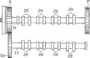
As shown in figure 14, the variable timing device of valve can be located at an end of the exhaust valve side of camshaft 10.A wheel P sends the rotatory force of crankshaft Cr to around the other end of camshaft 10 the variable timing device of valve.The actuation gear G of this device is sent to rotatory force by driven gear Ga the suction valve side of camshaft 11.The rotation of camshaft 11 makes the cam that is located on the camshaft 11 selectively open and close suction valve 102 (not shown).Variable valve timing gear changes the relative rotation phase between impeller 19 and the actuation gear G.The rotation phase that this has changed camshaft 11 has also changed the valve timing of suction valve 102.The superiority of the preferred embodiment of describing also can obtain by this structure.
The impeller 19 of the preferred embodiment of describing is provided with four blades 24.But the number of blade 24 does not limit.Therefore, more or less blade 24 can be set.But in the case, blade 24 must balance.Therefore preferably with the axis symmetric arrangement of blade 24, and with blade 24 equally spaced settings with respect to camshaft 11.
The various embodiments described above provide the structure of the valve timing that is used for changing suction valve 102.But variable valve timing gear can be located at outlet valve 103 sides of camshaft 11a, is used for changing the valve timing of outlet valve 103.Select for use as another, variable valve timing gear can be located at camshaft 11, on the 11a, is used for changing the valve timing of relevant suction valve 102 and outlet valve 103.
Therefore, these examples and embodiment are illustrative, are not determinate, and the present invention is limited to the details that provides, and can improve in the scope of the claim of enclosing.
Claims (17)
1. variable valve timing gear that is used for internal-combustion engine, this motor comprises a suction valve and an outlet valve, a camshaft and a crankshaft, wherein said camshaft operationally links to each other with crankshaft, and wherein said camshaft selectively shifts to an earlier date and delay between with respect to two extreme opposite angles of crankshaft, thereby based on the operating condition of described motor, selectively open and close described valve by variable timing, described device comprises:
One first rotor, it operationally links to each other with crankshaft;
One second rotor, it operationally links to each other with camshaft;
One in blade and the rotor forms whole;
One in the rotor is provided with groove and is used for holding blade, and it is relative with blade that described groove has a limit;
Has outstanding its second limit that leans against of blade on the part;
Overhanging element is biased in the device on second limit; And
First chamber is limited in the groove by blade, in first chamber, hold fluid, described fluid produces pressure and carries out relatively rotating of described first rotor and described second rotor, and wherein said overhanging element is slided on the limit, adjusts advancement amount or the retardation of camshaft with respect to crankshaft.
2. device as claimed in claim 1, comprise that further one second chamber is limited in the groove with respect to close first chamber of blade, wherein said second chamber holds fluid, and based on the different pressure of first chamber with second chamber, described camshaft shifts to an earlier date with respect to crankshaft and postpones.
3. device as claimed in claim 2 it is characterized in that the pressure in described first chamber makes camshaft shift to an earlier date with respect to crankshaft, and the pressure in described second chamber makes camshaft postpone with respect to crankshaft.
4. device as claimed in claim 3 further comprises:
Be used for selectively supplying with the device of fluid to first chamber and second chamber; And
Be used to start the device that described supplier is adjusted the Fluid Volume of supplying with described chamber.
5. device as claimed in claim 4 further comprises:
Described supplier comprises selectively the device of discharging fluid from first chamber and second chamber; And
Described starting arrangement comprises the device that is used for changing at supply of described chamber and discharge fluid, and the supply of the fluid in one of them chamber and discharge are opposite with another chamber execution.
6. device as claimed in claim 5 is characterized in that:
Described starting arrangement control supplier keeps the discharge and the supply of the fluid in two chambeies, thereby keeps current valve timing.
7. device as claimed in claim 2 is characterized in that:
Described overhanging element seals first chamber and second chamber, prevents that fluid from spilling from the chamber.
8. device as claimed in claim 7 is characterized in that:
Described overhanging element is near first chamber and away from second chamber.
9. device as claimed in claim 6 is characterized in that:
Described starting arrangement comprises that the ECU (Electrical Control Unit) of an output services signal and wherein said supplier comprise that one is connected to first chamber and second chamber, and according to the solenoid valve of working signal starting.
10. device as claimed in claim 9 is characterized in that:
Concrete working signal of wherein said ECU (Electrical Control Unit) output is realized and is not realized equating that wherein said solenoid valve leads in the chamber according to the fluid of this concrete working signal permission equivalent.
11. variable valve timing gear that is used for internal-combustion engine, this motor comprises a suction valve and an outlet valve, a camshaft and a crankshaft, wherein said camshaft operationally links to each other with crankshaft, and wherein said camshaft selectively shifts to an earlier date and delay between with respect to two extreme opposite angles of crankshaft, thereby based on the operating condition of described motor, selectively open and close described valve by variable valve timing, described device comprises:
One first rotor, it operationally links to each other with crankshaft;
One second rotor, it operationally links to each other with camshaft;
One in blade and the rotor forms whole;
One in the rotor is provided with groove and is used for holding blade, and it is relative with blade that described groove has a limit;
Has outstanding its second limit that leans against of blade on the part;
Overhanging element is biased in the device on second limit;
First chamber is limited in the groove by blade, holds fluid in first chamber;
One second chamber is limited in the groove with respect to blade near first chamber, and wherein said second chamber holds fluid, and based on the different pressure of first chamber with second chamber, and described camshaft with respect to crankshaft in advance and delay; And
Described overhanging element seals described first chamber and second chamber, prevents that fluid from spilling from the chamber.
12. the device as claim 11 is characterized in that:
Described overhanging element is near first chamber and away from second chamber.
13. the device as claim 12 further comprises:
Be used for selectively supplying with the device of fluid to first chamber and second chamber; And
Be used to start the device that described supplier is adjusted the Fluid Volume of supplying with described chamber.
14. the device as claim 15 further comprises:
Described supplier comprises selectively the device of discharging fluid from first chamber and second chamber; And
Described starting arrangement comprises the device that is used for changing at supply of described chamber and discharge fluid, and the supply of the fluid in one of them chamber and discharge are opposite with another chamber execution.
15. the device as claim 14 is characterized in that:
Described starting arrangement control supplier keeps the discharge and the supply of the fluid in two chambeies, thereby keeps current valve timing.
16. the device as claim 15 is characterized in that:
Described starting arrangement comprises that the ECU (Electrical Control Unit) of an output services signal and wherein said supplier comprise that one is connected to first chamber and second chamber, and according to the solenoid valve of working signal starting.
17. the device as claim 16 is characterized in that:
Concrete working signal of described ECU (Electrical Control Unit) output is realized and is not realized equating that wherein said solenoid valve leads in the chamber according to the fluid of this concrete working signal permission equivalent.
Priority Applications (1)
| Application Number | Priority Date | Filing Date | Title |
|---|---|---|---|
| CN 97113093 CN1178286A (en) | 1996-05-14 | 1997-05-14 | Variable valve timing apparatus for internal combustion engine |
Applications Claiming Priority (3)
| Application Number | Priority Date | Filing Date | Title |
|---|---|---|---|
| JP118884/96 | 1996-05-14 | ||
| JP142778/96 | 1996-06-05 | ||
| CN 97113093 CN1178286A (en) | 1996-05-14 | 1997-05-14 | Variable valve timing apparatus for internal combustion engine |
Publications (1)
| Publication Number | Publication Date |
|---|---|
| CN1178286A true CN1178286A (en) | 1998-04-08 |
Family
ID=5172571
Family Applications (1)
| Application Number | Title | Priority Date | Filing Date |
|---|---|---|---|
| CN 97113093 Pending CN1178286A (en) | 1996-05-14 | 1997-05-14 | Variable valve timing apparatus for internal combustion engine |
Country Status (1)
| Country | Link |
|---|---|
| CN (1) | CN1178286A (en) |
Cited By (4)
| Publication number | Priority date | Publication date | Assignee | Title |
|---|---|---|---|---|
| CN1298983C (en) * | 2000-12-12 | 2007-02-07 | 丰田自动车株式会社 | Controller of internal combustion engine |
| CN100339567C (en) * | 2003-08-28 | 2007-09-26 | 爱信精机株式会社 | Valve opening-closing timing control device |
| CN101109302B (en) * | 2006-07-19 | 2010-06-09 | 爱信精机株式会社 | Valve timing control device |
| CN104121052A (en) * | 2013-04-29 | 2014-10-29 | 舍弗勒技术有限两合公司 | Hydraulic cam shaft regulator with a local recess on a cam shaft flange face thereof |
-
1997
- 1997-05-14 CN CN 97113093 patent/CN1178286A/en active Pending
Cited By (4)
| Publication number | Priority date | Publication date | Assignee | Title |
|---|---|---|---|---|
| CN1298983C (en) * | 2000-12-12 | 2007-02-07 | 丰田自动车株式会社 | Controller of internal combustion engine |
| CN100339567C (en) * | 2003-08-28 | 2007-09-26 | 爱信精机株式会社 | Valve opening-closing timing control device |
| CN101109302B (en) * | 2006-07-19 | 2010-06-09 | 爱信精机株式会社 | Valve timing control device |
| CN104121052A (en) * | 2013-04-29 | 2014-10-29 | 舍弗勒技术有限两合公司 | Hydraulic cam shaft regulator with a local recess on a cam shaft flange face thereof |
Similar Documents
| Publication | Publication Date | Title |
|---|---|---|
| US8695548B2 (en) | Valve timing control apparatus | |
| RU2517992C2 (en) | Turbine blade and method of assembly of turbine rotor with such blade | |
| US7100555B2 (en) | Valve timing controller | |
| US7222598B2 (en) | Valve timing controller | |
| CN1991175A (en) | Variable displacement vane pump | |
| US7827949B2 (en) | Variable valve timing control apparatus of internal combustion engine | |
| US9062573B2 (en) | Valve timing controller | |
| CN1696476A (en) | Control valve for a camshaft timing phaser in an internal combustion engine | |
| JP4048067B2 (en) | Hydraulic balance multi vane hydraulic motor | |
| JP2005299671A (en) | Method of altering quantity of detected information sent to controller | |
| JP2005002992A (en) | Phase shifter | |
| US8955479B2 (en) | Variable valve timing control apparatus of internal combustion engine and method for assembling the same | |
| JP2009185719A (en) | Valve timing regulating device | |
| US20090071424A1 (en) | Valve timing control apparatus | |
| CN1178286A (en) | Variable valve timing apparatus for internal combustion engine | |
| US20190271313A1 (en) | Vane pump | |
| JPH11182216A (en) | Valve timing control device for internal combustion engine | |
| CN109209547B (en) | One-way clutch type variable valve timing apparatus and engine system thereof | |
| JP2013087626A (en) | Valve timing adjusting device | |
| CN1666017A (en) | Rotary valve seal | |
| JP4297434B2 (en) | Valve timing control device for internal combustion engine | |
| WO2017119234A1 (en) | Internal-combustion engine valve timing control device | |
| US10837326B2 (en) | Valve timing control device for internal combustion engine | |
| EP2305970B1 (en) | Valve timing control apparatus | |
| JP4257551B2 (en) | Cam phase variable device |
Legal Events
| Date | Code | Title | Description |
|---|---|---|---|
| C06 | Publication | ||
| PB01 | Publication | ||
| C01 | Deemed withdrawal of patent application (patent law 1993) | ||
| WD01 | Invention patent application deemed withdrawn after publication |