CN1178080C - Low-dispersion optical fiber and optical transmission system using low-dispersion optical fiber - Google Patents
Low-dispersion optical fiber and optical transmission system using low-dispersion optical fiber Download PDFInfo
- Publication number
- CN1178080C CN1178080C CNB018003249A CN01800324A CN1178080C CN 1178080 C CN1178080 C CN 1178080C CN B018003249 A CNB018003249 A CN B018003249A CN 01800324 A CN01800324 A CN 01800324A CN 1178080 C CN1178080 C CN 1178080C
- Authority
- CN
- China
- Prior art keywords
- fibre core
- refractive index
- dispersion
- nanometers
- fiber
- Prior art date
- Legal status (The legal status is an assumption and is not a legal conclusion. Google has not performed a legal analysis and makes no representation as to the accuracy of the status listed.)
- Expired - Fee Related
Links
Images


Classifications
-
- G—PHYSICS
- G02—OPTICS
- G02B—OPTICAL ELEMENTS, SYSTEMS OR APPARATUS
- G02B6/00—Light guides; Structural details of arrangements comprising light guides and other optical elements, e.g. couplings
- G02B6/02—Optical fibres with cladding with or without a coating
- G02B6/02004—Optical fibres with cladding with or without a coating characterised by the core effective area or mode field radius
- G02B6/02009—Large effective area or mode field radius, e.g. to reduce nonlinear effects in single mode fibres
-
- G—PHYSICS
- G02—OPTICS
- G02B—OPTICAL ELEMENTS, SYSTEMS OR APPARATUS
- G02B6/00—Light guides; Structural details of arrangements comprising light guides and other optical elements, e.g. couplings
- G02B6/02—Optical fibres with cladding with or without a coating
- G02B6/028—Optical fibres with cladding with or without a coating with core or cladding having graded refractive index
-
- G—PHYSICS
- G02—OPTICS
- G02B—OPTICAL ELEMENTS, SYSTEMS OR APPARATUS
- G02B6/00—Light guides; Structural details of arrangements comprising light guides and other optical elements, e.g. couplings
- G02B6/02—Optical fibres with cladding with or without a coating
-
- G—PHYSICS
- G02—OPTICS
- G02B—OPTICAL ELEMENTS, SYSTEMS OR APPARATUS
- G02B6/00—Light guides; Structural details of arrangements comprising light guides and other optical elements, e.g. couplings
- G02B6/02—Optical fibres with cladding with or without a coating
- G02B6/02004—Optical fibres with cladding with or without a coating characterised by the core effective area or mode field radius
- G02B6/02009—Large effective area or mode field radius, e.g. to reduce nonlinear effects in single mode fibres
- G02B6/02014—Effective area greater than 60 square microns in the C band, i.e. 1530-1565 nm
-
- G—PHYSICS
- G02—OPTICS
- G02B—OPTICAL ELEMENTS, SYSTEMS OR APPARATUS
- G02B6/00—Light guides; Structural details of arrangements comprising light guides and other optical elements, e.g. couplings
- G02B6/02—Optical fibres with cladding with or without a coating
- G02B6/02214—Optical fibres with cladding with or without a coating tailored to obtain the desired dispersion, e.g. dispersion shifted, dispersion flattened
- G02B6/02219—Characterised by the wavelength dispersion properties in the silica low loss window around 1550 nm, i.e. S, C, L and U bands from 1460-1675 nm
- G02B6/02228—Dispersion flattened fibres, i.e. having a low dispersion variation over an extended wavelength range
- G02B6/02238—Low dispersion slope fibres
- G02B6/02242—Low dispersion slope fibres having a dispersion slope <0.06 ps/km/nm2
-
- G—PHYSICS
- G02—OPTICS
- G02B—OPTICAL ELEMENTS, SYSTEMS OR APPARATUS
- G02B6/00—Light guides; Structural details of arrangements comprising light guides and other optical elements, e.g. couplings
- G02B6/02—Optical fibres with cladding with or without a coating
- G02B6/02214—Optical fibres with cladding with or without a coating tailored to obtain the desired dispersion, e.g. dispersion shifted, dispersion flattened
- G02B6/02219—Characterised by the wavelength dispersion properties in the silica low loss window around 1550 nm, i.e. S, C, L and U bands from 1460-1675 nm
- G02B6/02252—Negative dispersion fibres at 1550 nm
- G02B6/02257—Non-zero dispersion shifted fibres, i.e. having a small negative dispersion at 1550 nm, e.g. ITU-T G.655 dispersion between - 1.0 to - 10 ps/nm.km for avoiding nonlinear effects
-
- G—PHYSICS
- G02—OPTICS
- G02B—OPTICAL ELEMENTS, SYSTEMS OR APPARATUS
- G02B6/00—Light guides; Structural details of arrangements comprising light guides and other optical elements, e.g. couplings
- G02B6/02—Optical fibres with cladding with or without a coating
- G02B6/02214—Optical fibres with cladding with or without a coating tailored to obtain the desired dispersion, e.g. dispersion shifted, dispersion flattened
- G02B6/02219—Characterised by the wavelength dispersion properties in the silica low loss window around 1550 nm, i.e. S, C, L and U bands from 1460-1675 nm
- G02B6/02266—Positive dispersion fibres at 1550 nm
- G02B6/02271—Non-zero dispersion shifted fibres, i.e. having a small positive dispersion at 1550 nm, e.g. ITU-T G.655 dispersion between 1.0 to 10 ps/nm.km for avoiding nonlinear effects
-
- G—PHYSICS
- G02—OPTICS
- G02B—OPTICAL ELEMENTS, SYSTEMS OR APPARATUS
- G02B6/00—Light guides; Structural details of arrangements comprising light guides and other optical elements, e.g. couplings
- G02B6/02—Optical fibres with cladding with or without a coating
- G02B6/028—Optical fibres with cladding with or without a coating with core or cladding having graded refractive index
- G02B6/0286—Combination of graded index in the central core segment and a graded index layer external to the central core segment
-
- G—PHYSICS
- G02—OPTICS
- G02B—OPTICAL ELEMENTS, SYSTEMS OR APPARATUS
- G02B6/00—Light guides; Structural details of arrangements comprising light guides and other optical elements, e.g. couplings
- G02B6/02—Optical fibres with cladding with or without a coating
- G02B6/036—Optical fibres with cladding with or without a coating core or cladding comprising multiple layers
- G02B6/03616—Optical fibres characterised both by the number of different refractive index layers around the central core segment, i.e. around the innermost high index core layer, and their relative refractive index difference
- G02B6/03622—Optical fibres characterised both by the number of different refractive index layers around the central core segment, i.e. around the innermost high index core layer, and their relative refractive index difference having 2 layers only
- G02B6/03627—Optical fibres characterised both by the number of different refractive index layers around the central core segment, i.e. around the innermost high index core layer, and their relative refractive index difference having 2 layers only arranged - +
-
- G—PHYSICS
- G02—OPTICS
- G02B—OPTICAL ELEMENTS, SYSTEMS OR APPARATUS
- G02B6/00—Light guides; Structural details of arrangements comprising light guides and other optical elements, e.g. couplings
- G02B6/02—Optical fibres with cladding with or without a coating
- G02B6/036—Optical fibres with cladding with or without a coating core or cladding comprising multiple layers
- G02B6/03616—Optical fibres characterised both by the number of different refractive index layers around the central core segment, i.e. around the innermost high index core layer, and their relative refractive index difference
- G02B6/03622—Optical fibres characterised both by the number of different refractive index layers around the central core segment, i.e. around the innermost high index core layer, and their relative refractive index difference having 2 layers only
- G02B6/03633—Optical fibres characterised both by the number of different refractive index layers around the central core segment, i.e. around the innermost high index core layer, and their relative refractive index difference having 2 layers only arranged - -
-
- G—PHYSICS
- G02—OPTICS
- G02B—OPTICAL ELEMENTS, SYSTEMS OR APPARATUS
- G02B6/00—Light guides; Structural details of arrangements comprising light guides and other optical elements, e.g. couplings
- G02B6/02—Optical fibres with cladding with or without a coating
- G02B6/036—Optical fibres with cladding with or without a coating core or cladding comprising multiple layers
- G02B6/03616—Optical fibres characterised both by the number of different refractive index layers around the central core segment, i.e. around the innermost high index core layer, and their relative refractive index difference
- G02B6/03638—Optical fibres characterised both by the number of different refractive index layers around the central core segment, i.e. around the innermost high index core layer, and their relative refractive index difference having 3 layers only
- G02B6/03644—Optical fibres characterised both by the number of different refractive index layers around the central core segment, i.e. around the innermost high index core layer, and their relative refractive index difference having 3 layers only arranged - + -
-
- G—PHYSICS
- G02—OPTICS
- G02B—OPTICAL ELEMENTS, SYSTEMS OR APPARATUS
- G02B6/00—Light guides; Structural details of arrangements comprising light guides and other optical elements, e.g. couplings
- G02B6/02—Optical fibres with cladding with or without a coating
- G02B6/036—Optical fibres with cladding with or without a coating core or cladding comprising multiple layers
- G02B6/03616—Optical fibres characterised both by the number of different refractive index layers around the central core segment, i.e. around the innermost high index core layer, and their relative refractive index difference
- G02B6/03661—Optical fibres characterised both by the number of different refractive index layers around the central core segment, i.e. around the innermost high index core layer, and their relative refractive index difference having 4 layers only
- G02B6/03666—Optical fibres characterised both by the number of different refractive index layers around the central core segment, i.e. around the innermost high index core layer, and their relative refractive index difference having 4 layers only arranged - + - +
-
- G—PHYSICS
- G02—OPTICS
- G02B—OPTICAL ELEMENTS, SYSTEMS OR APPARATUS
- G02B6/00—Light guides; Structural details of arrangements comprising light guides and other optical elements, e.g. couplings
- G02B6/02—Optical fibres with cladding with or without a coating
- G02B6/02214—Optical fibres with cladding with or without a coating tailored to obtain the desired dispersion, e.g. dispersion shifted, dispersion flattened
- G02B6/02219—Characterised by the wavelength dispersion properties in the silica low loss window around 1550 nm, i.e. S, C, L and U bands from 1460-1675 nm
- G02B6/02252—Negative dispersion fibres at 1550 nm
- G02B6/02261—Dispersion compensating fibres, i.e. for compensating positive dispersion of other fibres
-
- G—PHYSICS
- G02—OPTICS
- G02B—OPTICAL ELEMENTS, SYSTEMS OR APPARATUS
- G02B6/00—Light guides; Structural details of arrangements comprising light guides and other optical elements, e.g. couplings
- G02B6/02—Optical fibres with cladding with or without a coating
- G02B6/02214—Optical fibres with cladding with or without a coating tailored to obtain the desired dispersion, e.g. dispersion shifted, dispersion flattened
- G02B6/0228—Characterised by the wavelength dispersion slope properties around 1550 nm
Abstract
A lower-dispersion optical fiber achieving both low wavelength dispersion in the usable wavelength region and enlarged effective core cross-section. The outer peripheral face of a center core (1) of the lower dispersion optical fiber is covered with a first side core (2) the outer peripheral face of the first side core (2) is covered with a second side core (3), and the outer peripheral face of the second side core (3) is covered with a clad (5). If the maximum refractive index of the center core (1) is n1, the minimum refractive index of the first side core (2) is n2, the maximum refractive index of the second side core (3) is n3, and the refractive index of the clad (5) is nc, a relation n1 > n3 > nc > n2 is satisfied. The relative refractive-index differences DELTA 1, DELTA 2, and DELTA 3 of the maximum refractive index of the center core (1), and the minimum refractive index of the first side core (2) to tose of the clad (5) are, respectively, in the ranges of 0.4 % <= DELTA 1 <= 0.7 %, -0.30 % <= DELTA 2 <= -0.05 %, and 0.2 % <= DELTA 3.
Description
Technical field
The present invention relates to a kind of low dispersion fiber that uses when being used for for example in 1.5 microns frequency bands, carrying out the wavelength-division multiplex light transmission, also relate to a kind of optical transmission system that adopts this low dispersion fiber.
Background technology
Along with the development of information society, the transmission capacity of information increases sharply, and realizes that in optical fiber communication high bit rate and high power capacity have become very urgent and can't an avoid problem.As realizing more a kind of method of high power capacity of high bit rate, utilize the optical fiber of doped with rare-earth elements, such as the light signal that can amplify the light form, doping Er
3+Er-doped fiber (EDF) be developed.Along with the image intensifer that utilizes those optical fiber is developed, the realization of high power signals light has developed rapidly.
Meanwhile,, utilize the light transmission communication of wave division multiplex mode to grow up, wherein have wavelength optical signals and in simple optical fiber, transmit in order in optical communication, to improve message capacity.The image intensifer that utilizes above-mentioned optical fiber is applied to adopt the optical communication of this wavelength-division multiplex light transmission (Wave division multiplexing optical transmission system), can improves message capacity further, thereby make the realization of long-distance transmissions within sight.
A representative example of fiber type image intensifer is EDFA (Erbium-Doped Fiber Amplifier (EDFA)), and it has the sort of EDF above-mentioned.Utilize this EDFA to carry out wavelength-division multiplex light transmission above-mentioned in 1.5 micron wave length frequency bands (wavelength from 1520 nanometers to 1620 nanometers), this frequency band is the gain frequency band of EDFA, is the transmission band that people are studying.
Fig. 6 (a) and 6 (b) have provided the example of the Refractive Index Profile o curve (refractive index profile) that is proposed as the optical fiber of wavelength-division multiplex light transmission in correlation technique, they are used to 1.5 micron wave length frequency bands above-mentioned, particularly as near the wavelength band (1.55 micron wave length frequency band) 1550 nanometers of transmission band (wavelength band of use).Fig. 6 (a) has provided a dimorphism refractive index distribution curve, and Fig. 6 (b) has provided the refractive index distribution curve of a W shape.
Optical fiber with dimorphism refractive index distribution curve by the big central fibre core 1 of: covering 5, refractive index ratio covering 5 and refractive index less than fibre core 1 but formed greater than first side fibre core 2 of the refractive index of covering 5.Refractive index distribution curve is that the optical fiber of W shape is greater than the central fibre core 1 of the refractive index of covering 5 and refractive index first side fibre core 2 less than covering 5 by: covering 5, refractive index.
In the optical fiber with above-described dimorphism refractive index distribution curve, near those optical fiber that have zero-dispersion wavelength 1.55 micron wave lengths are called dispersion shifted optical fiber.Because dispersion shifted optical fiber has zero-dispersion wavelength near 1.55 micron wave lengths, it is the centre wavelength of 1.55 micron wave length frequency bands, and the waveform distortion of the light signal that causes owing to chromatic dispersion in 1.55 micron wave length frequency bands can be inhibited.Yet at low-frequency range (down side), the generation of four-wave mixing non-linear phenomena is very obvious.Therefore, this dispersion shifted optical fiber because the appearance of four ripple mixed lights can cause the waveform distortion of flashlight, thereby can not carry out high-quality wavelength-division multiplex light transmission.
In order to overcome this shortcoming, the optical fiber that has the dimorphism refractive index distribution curve of zero-dispersion wavelength displacement from 1.55 micron wave length frequency bands has been developed.But people know that this optical fiber is very big at the chromatic dispersion gradient (gradient) of 1.55 micron wave length frequency bands.Owing to this reason, the dispersion differences in the wavelength band that is difficult to use in will the transmission of wavelength-division multiplex optical fiber with this optical fiber (between the wavelength band internal dispersion maximal value of use and the minimum value poor) is dwindled.So when adopting this optical fiber, the use wavelength band that is used for the wavelength-division multiplex light transmission can not be done very widely.
The effect of optical fiber with W shape refractive index distribution curve is identical with a kind of even dispersive optical fiber, because above-mentioned chromatic dispersion difference is very little.But, the effective core area of dimorphism refractive index distribution curve optical fiber (effective core the area) (zone that optical fiber is propagated effectively by it: A
Eff) approximately be 45 square microns, the effective core area of W shape refractive index distribution curve optical fiber is for example about 30 square microns, just 2/3rds of dimorphism refractive index distribution curve optical fiber.When effective core area when being so little, in the wavelength-division multiplex light transmission, there is such problem, the nonlinear effect that the optical signals that had both transmitted exists and degenerating in optical fiber.
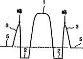
In order to overcome this shortcoming, the someone has proposed such thought, and that increases effective core area by the optical fiber that utilization has a kind of sectional type (segment) fiber core refractive index distribution curve shown in Fig. 6 (c) exactly.In Fig. 6 (c), the central fibre core of 1 expression; 2 first side fibre cores of expression; Second side fibre core of 3 expressions; Covering of 5 expressions.Yet, utilize this optical fiber, because very big at 1.5 micron wave length frequency band internal dispersion slopes, and very big in same wavelength band internal dispersion difference, when this optical fiber was used to division multiplexing optical with transmission, the problem that the flashlight waveform that is caused by chromatic dispersion worsens became very obvious.
Also have,, optical fiber must be put into optical cable for optical fiber is used for wave division multiplexing transmission system.Because require this optical cable to have such characteristic, both owing to the bending of optical fiber and optical fiber are subjected to loss that lateral pressure causes should be very little, so it is good also to require to be used for its flexural property of optical fiber of wavelength-division multiplex light transmission.
Yet, as previously mentioned, also there is not a kind of like this optical fiber, utilize it can obtain to realize necessary effective core area of high-quality wave division multiplexing transmission system and reduction dispersion differences simultaneously, realize that in addition the extraordinary optical fiber of bending loss characteristic is also very difficult.
Also have, in recent years, as image intensifer, raman amplifier is near practical application.Raman amplifier has wideer scalable wavelength band than existing EDFA, for example can amplify at 1450 nanometers light signal of specified wavelength frequency band arbitrarily in 1650 nanometer wavelength range.But, also do not make progress in the research of this wavelength coverage interior focusing fibre.
Summary of the invention
Therefore an object of the present invention is to provide a kind of low dispersion fiber, utilize it in the wavelength band that uses, to improve effective core area, the contractive color scattered error is other simultaneously, further reduce optical fiber put into after the optical cable because loss increase crooked and that lateral pressure causes, and an optical transmission system that utilizes this low dispersion fiber is provided.
The low dispersion fiber of first kind of structure provided by the invention, can realize this purpose and other purpose, it is a kind of like this dispersion shifted optical fiber, by on central fibre core, covering first side fibre core, on first side fibre core, cover second side fibre core, covering of covering forms on second side fibre core, it is characterised in that is write the largest refractive index of central fibre core as n1, the minimum refractive index of first side fibre core is write as n2, the largest refractive index of second side fibre core is write as n3, when being write the refractive index of covering as nc, n1>n3>nc>n2 is arranged; The largest refractive index of central authorities' fibre core is 0.4%≤Δ 1≤0.7% with respect to the refractive index contrast Δ 1 of covering; First side fibre core minimum refractive index with respect to the refractive index contrast Δ 2 of covering is-0.30%≤Δ 2≤-0.05%; The largest refractive index of second side fibre core is 0.2%≤Δ 3 with respect to the refractive index contrast Δ 3 of covering; The ratio (a1/a2) of the diameter a1 of fibre core and the diameter a2 of first side fibre core is 0.4 at least, is not more than 0.7; The diameter a3 of second side fibre core is not more than 1.6 with the ratio (a3/a2) of the diameter a2 of first side fibre core; Wherein, second side fibre core a kind of additive that mixed, it can improve silicon dioxide (SiO
2) refractive index; Be entrained in second additive in the side fibre core and a peak value arranged in optical fiber CONCENTRATION DISTRIBUTION radially.
The low dispersion fiber of second kind of structure provided by the invention is characterised in that except above-described first kind of structure, the position of this peak value is positioned on first side fibre core one side of second side fibre core radial center.
One low dispersion fiber of the third structure provided by the invention is characterised in that except above-described second kind of structure, additive wherein is germanium dioxide (GeO
2).
One low dispersion fiber of the 4th kind of structure provided by the invention is characterised in that, except above-described first kind of structure or second kind of structure or the third structure, between covering and second side fibre core, provide a little low-refraction clad section of the refractive index ratio covering.
The low dispersion fiber of the 5th kind of structure provided by the invention is characterised in that, except above-described first kind of structure or second kind of structure or the third structure, in being included in the wavelength band that 1450 nanometers use in the 1650 nano wave length frequency bands, there is not zero-dispersion wavelength.
The low dispersion fiber of the 6th kind of structure provided by the invention is characterised in that, except above-described the 4th kind of structure, do not have zero-dispersion wavelength in the wavelength band that is included in the use of 1450 nanometers in the 1650 nano wave length frequency bands.
The low dispersion fiber of the 7th kind of structure provided by the invention is characterised in that, except above-described first kind of structure or second kind of structure or the third structure or the 6th kind of structure, be not more than 2ps/nm/km in maximal value that is included in the dispersion values of wavelength band 1450 nanometers in the wavelength band of any 30 nanometer bandwidth of 1650 nanometers and the difference between the minimum value.
The low dispersion fiber of the 8th kind of structure provided by the invention is characterised in that, except above-described the 4th kind of structure, have in the wavelength band of any 30 nanometer bandwidth in 1650 nanometers being included in wavelength band 1450 nanometers, the maximal value of dispersion values and the difference between the minimum value are not more than 2ps/nm/km.
The low dispersion fiber of the 9th kind of structure provided by the invention is characterised in that, except above-described the 5th kind of structure, in bandwidth is 30 nanometers, be included in the wavelength band of wavelength band 1450 nanometers within 1650 nanometer range, the maximal value of dispersion values and the difference between the minimum value are not more than 2ps/nm/km.
The optical transmission system of the provided by the invention ten kind of structure is characterised in that, it has an optical transmission line, comprise any one dispersive optical fiber the above-described low dispersion fiber from first kind to the 9th kind of structure, and a kind of dispersion compensation device, it is born to the chromatic dispersion gradient in 1650 nanometer range in wavelength band 1450 nanometers, and the positive dispersion slope of optical transmission line is reduced by this dispersion compensation device in this wavelength band.
In this manual, concrete refractive index 1 above-mentioned, Δ 2 and Δ 3 usefulness following formula (1)~(3) define.
Δ1={(n1
2-nc
2)/2nc
2}×100 (1)
Δ2={(n2
2-nc
2)/2nc
2}×100 (2)
Δ3={(n3
2-nc
2)/2nc
2}×100 (3)
First purpose of low dispersion fiber of the present invention is in one group of wavelength band, for example in 1450 nanometers in 1650 nanometer wavelength range, increase effective core area, dwindle the dispersion differences in the wavelength band of use simultaneously.The present invention has optimized the index distribution of low dispersion fiber and its core diameter ratio, thereby makes it can realize this first purpose, has dwindled simultaneously when optical fiber is made into optical cable because loss increase crooked and that lateral pressure causes.Like this, utilize low dispersion fiber of the present invention, just might obtain promptly to increase effective core area, reduce the dispersion differences in the wavelength band that uses again simultaneously, and when further reducing optical fiber and be made into optical cable because loss increase crooked and that lateral pressure causes.The instantiation of low dispersion fiber of the present invention is discussed in implementing embodiment of the present invention from now on.
In a kind of structure of low dispersion fiber of the present invention, second side fibre core a kind of additive that mixed, it can improve the refractive index of silicon dioxide; The additive that second side fibre core advanced in doping has a peak value in the radially CONCENTRATION DISTRIBUTION of optical fiber; This peak value is on a side of first side fibre core of second side fibre core radial center.In another kind of structure, between covering and second side fibre core, a low-refraction clad section that the refractive index ratio covering is little is arranged.
In these structures, effective cut-off wavelength can be done very shortly.Therefore, utilize these structures, might make effective core area increase manyly, and be reduced in the interior dispersion differences of wavelength band of use more further, thus can the good low dispersion single-mode optical fiber of obtained performance.
Also have, in the above in a kind of structure of Miao Shuing, wherein be entrained in the additive that improves the refractive index of silicon dioxide in second side fibre core is positioned at second side fibre core radial center at the peak value of optical fiber CONCENTRATION DISTRIBUTION in the radial direction first side fibre core one side, if this additive is made of germanium dioxide, just can utilize existing optic fibre manufacturing technology to make this optical fiber at an easy rate.
If low dispersion fiber of the present invention has a kind of like this structure, make that it does not have zero-dispersion wavelength in the wavelength band that 1450 nanometers are used in 1650 nanometer wavelength range, for example in 1560 nanometers, do not have zero-dispersion wavelength in wavelength band 1530 nanometers, if for example in this wavelength band, carry out the wavelength-division multiplex light transmission, just can suppress the generation that four ripples mix, because therefore the waveform distortion that non-linear phenomena causes also can be inhibited.The wavelength band of use above-mentioned can freely be provided with in 1650 nanometer wavelength range in 1450 nanometers.
If in low dispersion fiber of the present invention, the maximal value of wavelength band internal dispersion value above-mentioned and the difference between the minimum value are 2ps/nm/km or littler, for example in this wavelength band, carry out in the wavelength-division multiplex light transmission, access inhibition because the waveform distortion that chromatic dispersion causes is sure.
Optical transmission system of the present invention utilizes a kind of optical transmission line, it comprises above-described low dispersion fiber, 1450 nanometers are in the wavelength band of 1650 nanometers in comprising this optical transmission line of low dispersion fiber, and positive chromatic dispersion gradient is reduced by the negative dispersion slope of dispersion compensation device.Utilize optical transmission system of the present invention, because the wavelength band internal dispersion slope of mentioning in the above can be done near 0, and the influence of chromatic dispersion can further be suppressed, so can construct a kind of optical transmission system, it can carry out high-quality wavelength-division multiplex transmission.
Description of drawings
The refractive index that Fig. 1 illustrates first embodiment in the low dispersion fiber of the present invention is in the detailed structure view of radially distribution (index distribution on an xsect);
Fig. 2 (a) illustrates the radially-arranged detailed structure view of refractive index of second embodiment of low dispersion fiber among the present invention, and Fig. 2 (b) illustrates that the optical fiber that is used for comparison is at radially index distribution synoptic diagram;
The 3rd embodiment that Fig. 3 illustrates low dispersion fiber among the present invention is in the detailed structure of radially index distribution;
Fig. 4 illustrates the dispersion characteristics of an embodiment of the optical transmission system that utilizes low dispersion fiber among the present invention, and the dispersion characteristics that are applied to the low dispersion fiber of this optical transmission system;
Fig. 5 (a) illustrates index distribution, and Fig. 5 (b) illustrates the dispersion characteristics of the dispersion compensation device of the embodiment that is applied to above-mentioned optical transmission system; With
Fig. 6 (a)~6 (c) illustrates that the optical fiber that is proposed to be used in the transmission of wavelength division multiplexed light in the correlation technique is in radially index distribution (index distribution on the xsect).
Preferred embodiment
In order to illustrate in greater detail the present invention, below a plurality of embodiment of the present invention will be described on the basis of accompanying drawing.In following explanation to embodiment, adopt same reference numerals with the parts that have same names in the prior art example, the description of repetition all has been removed.Fig. 1 illustrates the refractive index distribution curve (refractive index distribution structure) of first embodiment of low dispersion fiber among the present invention.
As shown in the figure, this low dispersion fiber has a central fibre core 1, and it is covered by first side fibre core 2; Covered second side fibre core 3 on first side fibre core 2; Covered a covering 5 on second side fibre core 3.Also have, in this low dispersion fiber, if write the largest refractive index of fibre core 1 as n1, write the minimum refractive index of first side fibre core 2 as n2, write the largest refractive index of second side fibre core 3 as n3, write the refractive index of covering 5 as nc, just had n1>n3>nc>n2.
The feature of the tool characteristic of this first embodiment of the present invention is the refractive index n c that maximal value n3 that the largest refractive index of second side fibre core 3 equals the refractive index of 0.2%, the second side fibre core 3 at least with respect to the refractive index contrast Δ 3 of covering 5 is far longer than covering 5.In this first embodiment, the largest refractive index of central authorities' fibre core 1 equals 0.4% at least with respect to the refractive index contrast Δ 1 of covering 5, be not more than 0.7% (0.4%≤Δ 1≤0.7%), the minimum refractive index of first side fibre core 2 equals-0.3% at least with respect to the refractive index contrast Δ 2 of covering 5, is not more than-0.05% (0.30%≤Δ 2≤-0.05%).
In this first embodiment, the largest refractive index of central authorities' fibre core 1 preferably equals 0.42% at least with respect to the refractive index contrast Δ 1 of covering 5, be not more than 0.62% (0.42%≤Δ 1≤0.62%), the minimum refractive index of first side fibre core 2 equals-0.25% with respect to refractive index contrast Δ 2 minimums of covering 5, is not more than-0.05% (0.25%≤Δ 2≤-0.05%).
In this first embodiment, preferably like this, the ratio (a1/a2) of the diameter a2 of the diameter a1 of fibre core 1 of central authorities and first side fibre core 2 equals 0.4 at least, and the ratio (a3/a2) that is not more than the diameter a2 of the diameter a3 of 0.7, the second side fibre core 3 and first side fibre core 2 is not more than 1.6.It is 1.5 better that the ratio (a3/a2) of the diameter a3 of second side fibre core 3 and the diameter a2 of first side fibre core 2 is no more than.
In the low dispersion fiber of this first embodiment, the structure of optical fiber is not to be restricted especially.Optical fiber with above-described refractive index distribution curve can be by the germanium dioxide (GeO that for example mixes in central fibre core 1 and second side fibre core 3
2), doped with fluorine (F) is worked it out in first side fibre core 2.The additive that second side fibre core 3 advanced in doping is not limited to germanium dioxide, can be other additive that can improve the refractive index of silicon dioxide, for example alundum (Al (AI
2O
3) and so on.
In example shown in Figure 1, the germanium dioxide of the central fibre core 1 that mixes has a peak value in optical fiber CONCENTRATION DISTRIBUTION radially, is positioned at the center of central fibre core 1.The germanium dioxide that doping is advanced in second side fibre core 3 also has a peak value in optical fiber CONCENTRATION DISTRIBUTION radially, and this peak value is on the radial center of second side fibre core 3.The peak value of the CONCENTRATION DISTRIBUTION of the germanium dioxide of optical fiber can also directly make progress at the optical fiber of central fibre core 1, rather than at the center.
In this first embodiment, utilize the ratio of the diameter of above-described refractive index distribution curve and central fibre core 1, first side fibre core 2 and second side fibre core 3, might promptly increase effective core area, reduce the dispersion differences in the wavelength band that uses again.Utilize the low dispersion fiber of this first embodiment, in the wavelength band that uses,, when optical fiber is made into optical cable, can obtain good performance because the crooked loss that causes is very little.
In the low dispersion fiber of this first embodiment, the effective core area minimum equals 45 square microns, absolute value (the unit: ps/nm/km) equal 2 at least of chromatic dispersion on any one position from wavelength 1530 nanometers to wavelength 1560 nanometers, be not more than 12, thereby make optical fiber in the wavelength band that uses, not have zero-dispersion wavelength.Also have, in the low dispersion fiber of this first embodiment, any one locational chromatic dispersion gradient value is not more than 0.05ps/nm in the wavelength band that uses
2/ km is not more than 2ps/nm/km in wavelength band internal dispersion maximal value of using and poor (dispersion differences) between the minimum value.
Illustrate in the above in the process of refractive index distribution curve and core diameter ratio that the inventor has obtained the characteristic of multiple optical fiber by testing and simulating.Found that, when refractive index contrast Δ 1 above-mentioned less than 0.4% the time, though can increase effective core area, reduce chromatic dispersion gradient, the bending loss of optical fiber often increases, and is difficult to keep good performance when optical fiber is formed optical cable.
On the other hand, the inventor finds that it is very big that chromatic dispersion gradient becomes when refractive index contrast Δ 1 surpasses 0.7%; The CHROMATIC DISPERSION IN FIBER OPTICS slope that chromatic dispersion gradient becomes and has the dimorphism refractive index distribution curve greater than above-described; And effective core area becomes identical with the fibre core area approximation of dimorphism refractive index distribution curve optical fiber.Owing to these reasons, as previously mentioned, in first embodiment of the present invention, refractive index contrast Δ 1 is chosen as 0.4% ~ 0.7%.
Though refractive index contrast Δ 1 can be arranged on any one position in the above scope, but when the refractive index distribution curve of central fibre core 1 is that a α power is (in the time of the distribution curve of α-power), refractive index contrast Δ 1 is preferably less when α is very big, when α is very little, preferably bigger.Refractive index distribution curve is that the shape that a α power distribution curve refers to refractive index is curve y=-x
α, the center of curve is at the center of fibre core.As a typical example, when α equaled 4 ~ 6, refractive index contrast Δ 1 was preferably between 0.53% to 0.60%.
When refractive index contrast Δ 2 less than-0.30% the time, though chromatic dispersion gradient is very little, effective core area has diminished also.When refractive index contrast Δ 2 greater than-0.05% the time, though that effective core area becomes is very big, it is approximate equally big with dimorphism refractive index distribution curve CHROMATIC DISPERSION IN FIBER OPTICS slope in the prior art that chromatic dispersion gradient becomes.Owing to these reasons, as previously mentioned, in first embodiment of the present invention, refractive index contrast Δ 2 is chosen as-0.30%≤Δ 2≤-0.05%.
Also have, in having the optical fiber of above-described refractive index distribution curve, because the diameter a1 of central fibre core 1 becomes less with the ratio (a1/a2) of the diameter a2 of first side fibre core 2, in the wavelength band of 1650 nanometers, often be difficult to obtain very low bending loss in 1450 nanometers.And can make effective cut-off wavelength elongated, and make fiber work become very difficult in the single mode mode.When ratio above-mentioned (a1/a2) less than 0.4 the time, 1450 nanometers bending loss in the wavelength band of 1650 nanometers increases highly significant, this optical fiber is not suitable for cable.
On the other hand, when ratio above-mentioned (a1/a2) greater than 0.7 the time, obtain the low dispersion values very difficulty that becomes, this optical fiber becomes and is not suitable in the wavelength-division multiplex light transmission of 1450 nanometers in the 1650 nano wave length frequency band ranges.Owing to these reasons, in first embodiment of the present invention, as previously mentioned, ratio above-mentioned (a1/a2) is set at minimum and equals 0.4, but is not more than 0.7.
When the diameter of second side fibre core 3 is very big, when the diameter a3 of second side fibre core 3 surpassed 1.6 with the ratio (a3/a2) of the diameter a2 of first side fibre core 2, effective cut-off wavelength was elongated, the single mode mode work of the optical fiber very difficulty that becomes.Owing to this reason, in first embodiment of the present invention, this ratio (a3/a2) is selected to and is not more than 1.6.
In this first embodiment, refractive index distribution curve and core diameter ratio are to determine on the basis of the research described in the above.Therefore, increase effective core area, dwindled the dispersion differences in the wavelength band that uses; The appearance that four ripples mix has obtained inhibition; The crooked loss that causes is very little in the wavelength band that uses; When making optical cable, optical fiber can obtain good performance.
In table 1, instantiation as first embodiment of the present invention, provided refractive index contrast Δ 1, Δ 2 and Δ 3 in example 1 ~ 9 in each example, the a1/a2 of core diameter and a2/a3 and core diameter a3 have provided the characteristic of each example simultaneously.The characteristic that is used for the example of comparison provides at table 2.
Table 1
| Δ1 | Δ2 | Δ3 | a1/a2 | a2/a3 | Chromatic dispersion | Chromatic dispersion gradient | Effective core area | Bending loss | Diameter a3 | |
| Unit | % | % | % | ps/nm/km | ps/nm 2/km | μm 2 | dB/m | μm | ||
| Example 1 | 0.50 | -0.05 | 0.40 | 0.45 | 0.80 | 4.1 | 0.044 | 54 | 3.5 | 18.4 |
| Example 2 | 0.58 | -0.15 | 0.35 | 0.42 | 0.75 | -2.5 | 0.035 | 48 | 2.0 | 18.4 |
| Example 3 | 0.47 | -0.10 | 0.42 | 0.475 | 0.80 | 2.6 | 0.026 | 56 | 8.5 | 19.1 |
| Example 4 | 0.57 | -0.15 | 0.45 | 0.464 | 0.78 | 2.2 | 0.045 | 61 | 9.9 | 19.2 |
| Example 5 | 0.55 | -0.10 | 0.37 | 0.445 | 0.75 | 3.2 | 0.032 | 58 | 3.1 | 21.2 |
| Example 6 | 0.54 | -0.12 | 0.41 | 0.457 | 0.81 | 5.8 | 0.054 | 69 | 2.5 | 19.4 |
| Example 7 | 0.53 | -0.15 | 0.35 | 0.533 | 0.75 | 5.2 | 0.046 | 55 | 1.1 | 18.5 |
| Example 8 | 0.56 | -0.20 | 0.27 | 0.67 | 0.68 | 5.2 | 0.048 | 53 | 0.5 | 17.4 |
| Example 9 | 0.58 | -0.20 | 0.31 | 0.63 | 0.71 | 4.0 | 0.045 | 50 | 0.05 | 16.3 |
Table 2
| Δ1 | Δ2 | a1/a2 | Chromatic dispersion | Chromatic dispersion gradient | Effective core area | Bending loss | |
| Unit | % | % | ps/nm/km | ps/nm 2/km | μm 2 | dB/m | |
| Comparative example 1 | 0.55 | -0.45 | 0.55 | -0.8 | 0.009 | 37 | 8.1 |
| Comparative example 2 | 0.8 | 0.2 | 0.36 | 0.5 | 0.0845 | 45 | 1.8 |
In table 1 and table 2, chromatic dispersion, chromatic dispersion gradient, effective core area (A
Eff) and the value of bending loss all be value on wavelength 1550 nanometers.The bending loss value all is the value of fibre-optical bending diameter when being 20 millimeters.Although in table 1, do not provide, in the optical fiber of all examples 1 ~ 9, short wavelength's one side of the wavelength band that effective cut-off wavelength uses in 1650 nanometers in wavelength coverage 1450 nanometers, the work of single mode mode is fine.
Specifically, in example 8 and example 9, bending loss is less than 1dB/m, and when optical fiber was made optical cable, being not only loss increase crooked and that lateral pressure causes can be reduced, and the infringement increase that small bending causes also can be reduced.
In table 2, comparative example 1 is the W shape refractive index distribution curve optical fiber of Fig. 6 (b) shown type, and comparative example 2 is the sort of dimorphism refractive index distribution curve optical fiber shown in Fig. 6 (a).In table 2, refractive index contrast Δ 1 is to obtain according to the mode in above-described first embodiment, and in the situation of comparative example 1, refractive index contrast Δ 2 also is to obtain according to the same way as in above-described first embodiment.In the situation of comparative example 2, the largest refractive index of refractive index contrast Δ 2 first side fibre cores 2 of explanation is with respect to the refractive index contrast of covering 5, be that the expression formula (2) of utilizing the front obtains, wherein the largest refractive index of first side fibre core 2 is n2, and the refractive index of covering 5 is nc.
Characteristic from table 1 and table 2 relatively can be clear that, effective core area is greater than the effective core area in comparative example 1 and the example 2 in the example 9 at example 1, and chromatic dispersion gradient is less than the chromatic dispersion gradient in comparative example 1 and the comparative example 2.Like this, by example 1 is compared with comparative example 1 and comparative example 2 to example 9, can affirm that this first embodiment of the present invention has good characteristic.That is to say, utilize first embodiment of the present invention, can increase effective core area, can be reduced in the interior dispersion differences of wavelength band of use again, also have, in the wavelength band that uses, when the fibre-optical bending diameter is 20 millimeters, because the crooked loss that causes is very little, is lower than 20dB/m, thereby can obtains good performance when optical fiber is made optical cable.
Next step will describe second embodiment of low dispersion fiber among the present invention.The refractive index distribution curve of second embodiment described herein is shown in Fig. 2 (a).In this low dispersion fiber, the refractive index of second side fibre core 3 supposes that the refractive index peak at its maximal value place is positioned at a side of first side fibre core 2 of second side fibre core 3 radial center.Otherwise the refractive index distribution curve shown in Fig. 2 (a) refractive index distribution curve with shown in Figure 1 basically is identical.The refractive index peak of second side fibre core 3 is preferably as much as possible near first side fibre core 2 one sides.
Refractive index distribution curve shown in Fig. 2 (a) is by will be as additive, is used for improving that the position arrangement at the peak of the distribution that the concentration of the germanium dioxide of the refractive index that is entrained in second silicon dioxide in the side fibre core 3 directly makes progress at optical fiber obtains in a side of second first side fibre core 2 of side fibre core 3 radial center.
Because second embodiment of the present invention has such refractive index distribution curve, just obtained the effect that effective cut-off wavelength is shortened, in the whole wavelength band scope of using, sure enough this optical fiber carries out the single mode mode and works.
As with shown in essentially identical Fig. 2 of structure (b) of example 10, as characteristic and structure explanation in table 3 of the example 10 of an instantiation of second embodiment.The also explanation in table 3 of the structure of test sample 1 and characteristic, the CONCENTRATION DISTRIBUTION of germanium dioxide of wherein mixing second side fibre core 3 radially are constants at optical fiber basically.
Table 3
| Δ1 | Δ2 | Δ3 | a1/a2 | a3/a2 | Chromatic dispersion | Chromatic dispersion gradient | Effective core area | Effective cut-off wavelength | |
| Unit | % | % | % | ps/nm/km | ps/nm 2/km | μm 2 | nm | ||
| Example 10 | 0.525 | -0.15 | 0.35 | 0.547 | 1.33 | 3.11 | 0.044 | 55 | 1516 |
| | 0.525 | -0.15 | 0.35 | 0.547 | 1.33 | 3.11 | 0.044 | 56 | 1834 |
Also have, be different from the optical fiber of the parameter of example 10 as parameter, the inventor has constructed example 11 and 12, the concentration of the germanium dioxide of second the side fibre core 3 that wherein mix in the position at the peak of optical fiber distribution radially near second side fibre core 2 one side.These examples 11 and 12 structure and characteristic explanation in table 4.In table 4, the location tables of concentration at the peak of optical fiber distribution radially of the germanium dioxide in second side fibre core 3 is shown: first side fibre core 2 one sides are 0, and covering 5 is 1.
Table 4 gives with example 11 and 12 has the test sample 2 of basic identical parameter and 3 structure and characteristic, but the concentration of germanium dioxide of mixing second side fibre core 3 in the position at the peak of optical fiber distribution radially more near covering 5 one sides.
Table 4
| Δ1 | Δ2 | Δ3 | a1/a2 | a3/a2 | The position of germanium dioxide concentration peak | Chromatic dispersion | Chromatic dispersion gradient | Effective core area | Effective cut-off wavelength | Diameter a3 | |
| Unit | % | % | % | ps/nm/km | ps/nm 2/km | μm 2 | nm | μm | |||
| Example 1 | 0.57 | -0.20 | 0.30 | 0.547 | 1.39 | 0.07 | 3.58 | 0.048 | 49 | 1293 | 15.7 |
| Example 2 | 0.57 | -0.20 | 0.30 | 0.547 | 1.39 | 0.29 | 3.49 | 0.047 | 49 | 1321 | 15.8 |
| | 0.57 | -0.20 | 0.30 | 0.547 | 1.39 | 0.57 | 3.40 | 0.046 | 49 | 1354 | 15.8 |
| | 0.57 | -0.20 | 0.30 | 0.547 | 1.39 | 0.86 | 3.36 | 0.044 | 48 | 1381 | 15.8 |
Can be clear that from these tables along with the difference that is entrained in germanium dioxide CONCENTRATION DISTRIBUTION in second side fibre core 3, effective cut-off wavelength is different significantly.
Here, in the example shown in the table 4, provided bending loss and be the variation of characteristic under about 1 decibel every meter situation, when the refractive index peak of second side fibre core 3 moved towards the direction of first side fibre core 2 of second side fibre core radial center, chromatic dispersion and chromatic dispersion gradient often increased slightly.Yet, except the refractive index peak that moves second side fibre core 3, might adjust chromatic dispersion and chromatic dispersion gradient value with a kind of method.For example, can change the refractive index of central fibre core 1 or the refractive index of first side fibre core 2.
The effect of adjusting dispersion values and chromatic dispersion gradient is preferably by shifting to the position at the refractive index peak of second side fibre core 3 at 1/3rd width places of second side fibre core 3 of first side fibre core 2 one sides.This also is best mode from manufacturability and the angle of making chromatic dispersion.
The inventor finds, when the diameter a1 of refractive index contrast Δ 1, Δ 2 and Δ 3, central fibre core 1 is set at scope specified in the description with reference to figure 1 with the ratio (a3/a2) between the diameter a2 of first side fibre core 2 with the diameter a3 of the ratio (a1/a2) of the diameter a2 of first side fibre core 2 and second side fibre core 3 in, make effective core area much bigger, when being reduced in the wavelength band internal dispersion difference of use simultaneously, occur the elongated situation of effective cut-off wavelength sometimes, concrete condition depends on the value (for example in test sample 1) of setting.
That is to say, generally speaking, in optical fiber, provide second side fibre core 3 to increase effective core area A
EffThe time, cutoff wavelength can be shifted to long wavelength's one side.For example, under the situation just as the test sample in table 31, in the wavelength band that 1450 nanometers are used in 1650 nanometer wavelength range, optical fiber might can not be operated under the single mode mode.
Consider this point, the inventor has carried out various researchs, attempts effective cut-off wavelength is shifted to short wavelength's one side, makes the work of single mode mode become possibility.Found that, when the index distribution of second side fibre core 3 adopts for example the sort of distribution shown in Fig. 2 (a), shown in example 10, example 11 and example 12, might in the wavelength band that uses, shorten effective cut-off wavelength to a greater degree, increase effective core area, reduce dispersion differences.
That is to say that shown in example 10, example 11 and the example 12 shown in Fig. 2 (a) and table 3, table 4, the refractive index peak of second side fibre core 3 is moved toward first side fibre core 2 one sides of second side fibre core 3 radial center.So just cutoff wavelength has been shifted to short wavelength's one side, thereby can have been obtained a kind of like this optical fiber, it can be operated under the single mode mode in the wavelength band that 1450 nanometers are used in 1650 nanometer wavelength range.
The inventor thinks that the reason of this phenomenon is as follows.In the communication mode of optical fiber, LP
0m(m=2,3 ...) and LP
11The Electric Field Distribution that a wide range is upwards arranged in the footpath of optical fiber.Therefore, a side of first side fibre core 2 of the radial center by the refractive index peak of second side fibre core 3 being shifted to second side fibre core 3 might prevent that light is with LP
0mPattern and LP
11Mode propagation keeps the LP that light is propagated simultaneously in optical fiber
01The influence of pattern is very little, thereby makes the work of single mode mode become possibility.
On the basis of this research, described the structure of first embodiment of the present invention, and the above-mentioned effect shown in table 3 and the table 4 is provided.
Begin to describe the 3rd embodiment of low dispersion fiber among the present invention below.The refractive index distribution curve of the 3rd embodiment as shown in Figure 3.Except providing between covering 5 and second the side fibre core 3 the low-refraction clad section that has than low-refraction, this refractive index distribution curve refractive index distribution curve with shown in Figure 1 basically is identical.
The research that the inventor specifies the structure shown in Fig. 2 (a) to carry out according to the front has been carried out same research to the low dispersion fiber with this structure.Structure shown in Figure 3 is appointment on the basis of this research, by this low-refraction clad section 4 is provided, getting peaked refractive index peak with the refractive index of second side fibre core 3, to shift to first side fibre core 2 one sides of second side fibre core 3 radial center the same, can obtain same effect.
The structure of table 5 illustrated example 13 and characteristic, as an instantiation of this embodiment, it has the structure and the characteristic of low-refraction clad section 4 and test sample 4, and is basic identical with the structure of example 13, but does not have the low-refraction clad section.Can be clear that from this table,, might shorten effective cut-off wavelength by between covering 5 and second side fibre core 3, providing low-refraction clad section 4.
Table 5
| Δ1 | Δ2 | Δ3 | Δ4 | a1/a2 | a3/a 2 | a4/a 3 | Chromatic dispersion | Chromatic dispersion gradient | Effective core area | Effective cut-off wavelength | Diameter | |
| Unit | % | % | % | % | ps/nm/km | ps/nm 2/km | μm 2 | nm | μm | |||
| Example 3 | 0.425 | -0.17 | 0.415 | -0.20 | 0.475 | 1.35 | 1.80 | 4.82 | 0.046 | 64 | 1498 | 21.9 |
| Test sample 4 | 0.425 | -0.17 | 0.415 | 0.475 | 1.35 | 5.251 | 0.022 | 67 | 2407 | 24.2 |
An embodiment of optical transmission system among the present invention is described below.This optical transmission system has an optical transmission line, and it comprises at least a low dispersion fiber of one of above-described embodiment, also comprises a kind of dispersion compensation device, and it is born to the chromatic dispersion gradient in the 1650 nano wave length frequency band ranges in 1450 nanometers.This class optical transmission system is characterised in that the positive chromatic dispersion gradient of the optical transmission line that comprises low dispersion fiber reduces by dispersion compensation device.
As an example, a structure by will having the example 7 in the table 1 and a low dispersion fiber of characteristic couple together with the dispersion compensation device with negative chromatic dispersion and negative chromatic dispersion gradient and constitute an optical transmission system.
Dispersion compensation device in this application is to utilize the dispersion wavelength optical fiber with the sort of refractive index distribution curve of Fig. 5 (a) to make.That is to say that dispersion compensation device is to utilize to have first side fibre core 2 and be covered with central fibre core 1, second side fibre core 3 and be covered with the dispersion compensating fiber that first side fibre core 2 and covering 5 cover second side fibre core 3 and make.
In this dispersion compensating fiber, if write the largest refractive index of central fibre core 1 as n1, write the minimum refractive index of second side fibre core 2 as n2, write the largest refractive index of second side fibre core 3 as n3, and write the refractive index of covering 5 as nc, n1>n3>nc>n2 is just arranged.In this dispersion compensating fiber, the value Δ 1 of refractive index contrast, Δ 2 and Δ 3 are different from the value in the low dispersion fiber embodiment among above-described the present invention, and Δ 1 approximately is 2.85%, and Δ 2 approximately is-1%, and Δ 3 approximately is 1.28%.Core diameter approximately is 1/3/3.7 than (a1/a2/a3).
There are a negative chromatic dispersion (for example on wavelength 1550 nanometers approximately-150ps/nm/km or lower) and a negative chromatic dispersion gradient (about-2.18ps/nm in 1450 nanometers dispersion characteristics of this dispersion compensation device in the 1650 nano wave length frequency bands
2/ km), the absolute value of these values is all very big.Therefore, in this optical transmission system, the length of the low dispersion fiber of example 7 is 98 to 2 with the length ratio of dispersion compensation device.
In 1600 nano wave length frequency bands, this optical transmission system has the illustrated dispersion characteristics of curve a of Fig. 4 in 1530 nanometers.Low dispersion fiber is in the dispersion characteristics of 1530 nanometers in the 1600 nano wave length frequency bands in the curve b illustrated example 7 among Fig. 4.
Can be clear that from Fig. 4, the dispersion compensation device that will have the sort of negative dispersion slope shown in Fig. 5 (b) follows low dispersion fiber 7 to couple together when constituting optical transmission system, in the wavelength band that uses (be 1450 nanometers in this case in 1650 nanometer wavelength range a wavelength band), the dispersion differences in the optical transmission system is done as a whole can being reduced widely.An example of dispersion compensation device that is used for this embodiment of optical transmission system of the present invention is such device, as previously mentioned, also has a negative chromatic dispersion gradient that absolute value is very big.
When adopting this dispersion compensation device, as mentioned above, the length of this device can shorten.Therefore, the application of this dispersion compensation device can reduce the influence to nonlinear characteristic and the similar characteristics except dispersion characteristics, and make structure have the superperformance of the low dispersion fiber in the embodiment of front, and the optical transmission system that can carry out the wavelength-division multiplex transmission in high quality become possibility.
The present invention is not limited to above-described embodiment, can adopt the various pattern of the present invention of putting into practice.For example, in optical transmission system of the present invention, comprise the front one of embodiment low dispersion fiber and in the wavelength band that uses, have dispersion differences in the wavelength band that an optical transmission line of the dispersion compensation device of negative chromatic dispersion gradient is used to reduce to use.Therefore, in an embodiment of optical transmission system of the present invention, this optical transmission line can be by following another one optical fiber with the low dispersion fiber of one of top embodiment, and the optical fiber that for example can carry out the work of single mode mode couples together and makes.
How convenient the structure of dispersion compensation device of this embodiment that is applied to optical transmission line is not restricted especially, can just how to be provided with.But, when this dispersion compensation device is when making of above-described dispersion compensating fiber, just can make this device at an easy rate, and the optical transmission line that its attendant of a stage actor draws together low dispersion fiber is coupled together.
Also have, in the embodiment of the low dispersion fiber of Miao Shuing, germanium dioxide is doped into central fibre core 1 and second side fibre core 3 in the above, and fluorine (F) is doped into first side fibre core 2.But, by into first side fibre core 2 that germanium dioxide and F are mixed, and adjusting their doping, low dispersion fiber embodiment can also have Fig. 1, Fig. 2 or the sort of refractive index distribution curve shown in Figure 3 among the present invention.Also have, the composition of low dispersion fiber also can change among the present invention.
In addition, though in each embodiment in the embodiment of front, the low dispersion fiber of structure does not have zero-dispersion wavelength in 1530 nanometers in 1560 nano wave length frequency bands, but low dispersion fiber of the present invention can be formed in the wavelength band of any one use that 1450 nanometers comprise in the wavelength band of 1650 nanometers and do not have zero-dispersion wavelength.When low dispersion fiber of the present invention is constructed in this manner, because in the wavelength band that uses, carry out in the wavelength-division multiplex transmission, the generation that four ripples mix can be inhibited, so might obtain to be suitable for carrying out the low dispersion fiber of wavelength-division multiplex transmission in wideer frequency band.
As mentioned above, low dispersion fiber of the present invention and utilize the optical transmission system of this low dispersion fiber can either increase effective core area, the dispersion differences in the wavelength band that can reduce to use again, thereby be particularly suitable for the wavelength-division multiplex transmission.
Claims (10)
1. low dispersion fiber, it is by cover first side fibre core on fibre core, on first side fibre core, cover second side fibre core, and on second side fibre core, cover a kind of dispersion shifted optical fiber that covering forms, wherein write the largest refractive index of fibre core as n1, write the minimum refractive index of first side fibre core as n2, write the largest refractive index of second side fibre core as n3, write the refractive index of covering as nc, just had n1>n3>nc>n2; The largest refractive index of fibre core is 0.4%≤Δ 1≤0.7% with respect to the refractive index contrast Δ 1 of covering; The minimum refractive index of first side fibre core with respect to the refractive index contrast Δ 2 of covering is-0.30%≤Δ 2≤-0.05%; The largest refractive index of second side fibre core is 0.2%≤Δ 3 with respect to the refractive index contrast Δ 3 of covering; The diameter a1 of fibre core is 0.4 with ratio (a1/a2) minimum between the diameter a2 of first side fibre core, is no more than 0.7; The diameter a3 of second side fibre core is no more than 1.6 with the ratio (a3/a2) between the diameter a2 of first side fibre core; It is characterized in that, second side fibre core a kind of additive that mixed, it can improve the refractive index of silicon dioxide; Be entrained in the CONCENTRATION DISTRIBUTION that second additive in the side fibre core directly make progress at optical fiber a peak is arranged.
2. low dispersion fiber as claimed in claim 1, the position at peak wherein is in first side fibre core one side of second side fibre core radial center.
3. low dispersion fiber as claimed in claim 2, additive wherein is a germanium dioxide.
4. as described any one low dispersion fiber of claim 1 to 3, wherein between covering and second side fibre core, provide the refractive index ratio covering low low-refraction clad section.
As claim 1 to described any one low dispersion fiber of claim 3, in the wavelength band of the use that 1450 nanometers comprise in the wavelength band of 1650 nanometers, do not have zero-dispersion wavelength.
6. low dispersion fiber as claimed in claim 4 does not have zero-dispersion wavelength in the wavelength band of the use that 1450 nanometers comprise in the 1650 nano wave length frequency bands.
7. as described any one the low dispersion fiber of claim 1 to 3 and claim 6, in the wavelength band comprising any bandwidth that has 30 nanometers in wavelength band 1450 nanometers in 1650 nanometers, the maximal value of dispersion values and the difference between the minimum value are not more than 2ps/nm/km.
8. low dispersion fiber as claimed in claim 4, wherein the maximal value of the dispersion values in the wavelength band with 30 nanometer bandwidth that 1450 nanometers comprise to the wavelength band of 1650 nanometers and the difference between the minimum value are not more than 2ps/nm/km.
9. low dispersion fiber as claimed in claim 5, wherein the minimum value of dispersion values and the difference between the maximal value are not more than 2ps/nm/km in the wavelength band with any bandwidth of 30 nanometers that comprises in the wavelength band of 1650 nanometers of 1450 nanometers.
10. optical transmission system, comprise an optical transmission line, comprise as claim 1 to described any one low dispersion fiber of claim 9, with a dispersion compensation device, it is born to the chromatic dispersion gradient in the wavelength band of 1650 nanometers in 1450 nanometers, and wherein the positive chromatic dispersion gradient of optical transmission line is reduced by this dispersion compensation device in this wavelength band.
Applications Claiming Priority (3)
| Application Number | Priority Date | Filing Date | Title |
|---|---|---|---|
| JP49089/00 | 2000-02-25 | ||
| JP49089/2000 | 2000-02-25 | ||
| JP2000049089 | 2000-02-25 |
Publications (2)
| Publication Number | Publication Date |
|---|---|
| CN1363049A CN1363049A (en) | 2002-08-07 |
| CN1178080C true CN1178080C (en) | 2004-12-01 |
Family
ID=18571075
Family Applications (1)
| Application Number | Title | Priority Date | Filing Date |
|---|---|---|---|
| CNB018003249A Expired - Fee Related CN1178080C (en) | 2000-02-25 | 2001-02-23 | Low-dispersion optical fiber and optical transmission system using low-dispersion optical fiber |
Country Status (9)
| Country | Link |
|---|---|
| US (2) | US6684018B2 (en) |
| EP (1) | EP1189082A4 (en) |
| KR (1) | KR20010113806A (en) |
| CN (1) | CN1178080C (en) |
| BR (1) | BR0104593A (en) |
| CA (1) | CA2368327A1 (en) |
| HK (1) | HK1045564A1 (en) |
| RU (1) | RU2216755C2 (en) |
| WO (1) | WO2001063329A1 (en) |
Families Citing this family (20)
| Publication number | Priority date | Publication date | Assignee | Title |
|---|---|---|---|---|
| CN1178080C (en) * | 2000-02-25 | 2004-12-01 | 古河电气工业株式会社 | Low-dispersion optical fiber and optical transmission system using low-dispersion optical fiber |
| KR20030026340A (en) | 2000-08-16 | 2003-03-31 | 코닝 인코포레이티드 | Optical fiber with large effective area, low dispersion and low dispersion slope |
| JP2002341157A (en) * | 2001-03-15 | 2002-11-27 | Fujikura Ltd | Wavelength multiplex transmission line and dispersion compensating optical fiber used for the same |
| US20030059186A1 (en) * | 2001-09-26 | 2003-03-27 | Hebgen Peter G. | L-band dispersion compensating fiber and transmission system including same |
| JP3886771B2 (en) | 2001-10-29 | 2007-02-28 | 株式会社フジクラ | Single mode optical fiber and composite optical line for WDM |
| JP2003156649A (en) * | 2001-11-19 | 2003-05-30 | Furukawa Electric Co Ltd:The | Optical fiber |
| JP2003227959A (en) * | 2002-02-04 | 2003-08-15 | Furukawa Electric Co Ltd:The | Single mode optical fiber for wavelength multiplex transmission |
| EP1474712A1 (en) | 2002-02-15 | 2004-11-10 | Corning Incorporated | Low slope dispersion shifted optical fiber |
| EP1530735A1 (en) * | 2002-07-31 | 2005-05-18 | Corning Incorporated | Non-zero dispersion shifted optical fiber having large effective area, low slope and low zero dispersion |
| US20040076392A1 (en) * | 2002-10-17 | 2004-04-22 | Bickham Scott R. | Low Kappa, dual-moat DC fiber and optical transmission line |
| JP2004177817A (en) * | 2002-11-28 | 2004-06-24 | Sumitomo Electric Ind Ltd | Optical fiber and optical module |
| US7103251B2 (en) * | 2002-12-31 | 2006-09-05 | Corning Incorporated | Dispersion flattened NZDSF fiber |
| KR100506311B1 (en) * | 2003-01-20 | 2005-08-05 | 삼성전자주식회사 | Wide-band dispersion controlled optical fiber |
| US6959137B2 (en) * | 2003-06-11 | 2005-10-25 | Fitel U.S.A. Corporation | Large-effective-area inverse dispersion compensating fiber, and a transmission line incorporating the same |
| US7024083B2 (en) * | 2004-02-20 | 2006-04-04 | Corning Incorporated | Non-zero dispersion shifted optical fiber |
| JP4286863B2 (en) | 2004-10-22 | 2009-07-01 | 株式会社フジクラ | Optical fiber |
| US7106934B1 (en) | 2005-06-30 | 2006-09-12 | Corning Incorporated | Non-zero dispersion shifted optical fiber |
| US8693834B2 (en) * | 2011-08-15 | 2014-04-08 | Corning Incorporated | Few mode optical fibers for mode division multiplexing |
| JP6890638B2 (en) * | 2019-08-05 | 2021-06-18 | 京セラ株式会社 | Fiber optic power supply system and fiber optic cable |
| JP6889225B2 (en) * | 2019-10-21 | 2021-06-18 | 京セラ株式会社 | Fiber optic power supply system |
Family Cites Families (24)
| Publication number | Priority date | Publication date | Assignee | Title |
|---|---|---|---|---|
| DE972828C (en) | 1955-05-13 | 1959-10-01 | Maschf Augsburg Nuernberg Ag | Control device for a gas suspension of vehicles |
| JPH01184159A (en) * | 1988-01-19 | 1989-07-21 | Nitsuko Corp | Printer |
| US5822488A (en) * | 1995-10-04 | 1998-10-13 | Sumitomo Electric Industries, Inc. | Single-mode optical fiber with plural core portions |
| JPH09211249A (en) * | 1995-11-28 | 1997-08-15 | Sumitomo Electric Ind Ltd | Single-mode optical fiber |
| TW342460B (en) * | 1996-01-16 | 1998-10-11 | Sumitomo Electric Industries | A dispersion shift fiber |
| AU714957B2 (en) * | 1996-07-31 | 2000-01-13 | Corning Incorporated | Dispersion compensating single mode waveguide |
| CA2229280A1 (en) * | 1997-02-12 | 1998-08-12 | Sumitomo Electric Industries, Ltd. | Dispersion-shifted fiber |
| DE19712828A1 (en) | 1997-03-26 | 1998-10-15 | Sick Ag | Light curtain and process for its manufacture |
| JPH10339819A (en) | 1997-06-05 | 1998-12-22 | Furukawa Electric Co Ltd:The | Optical fiber for optical amplification |
| JPH1184159A (en) * | 1997-09-10 | 1999-03-26 | Furukawa Electric Co Ltd:The | Dispersion flat fiber |
| KR100353755B1 (en) * | 1997-12-05 | 2002-09-27 | 스미토모덴키고교가부시키가이샤 | Dispersion flat optical fiber |
| EP1044385A1 (en) * | 1997-12-30 | 2000-10-18 | Samsung Electronics Co., Ltd. | Single mode optical fiber |
| US5905838A (en) * | 1998-02-18 | 1999-05-18 | Lucent Technologies Inc. | Dual window WDM optical fiber communication |
| AU1686699A (en) * | 1998-04-30 | 1999-11-23 | Sumitomo Electric Industries, Ltd. | Optical fiber |
| FR2783609B1 (en) * | 1998-09-17 | 2002-08-30 | Cit Alcatel | OPTIMIZED SINGLE-MODE OPTICAL FIBER FOR HIGH SPEEDS |
| EP1054275B1 (en) * | 1998-12-03 | 2008-05-07 | Sumitomo Electric Industries, Ltd. | Dispersion equalization optical fiber and optical transmission line including the same |
| US6606437B1 (en) * | 1999-02-22 | 2003-08-12 | The Furukawa Electric Co., Ltd. | Optical transmission line, negative dispersion optical fiber used for the optical transmission line, and optical transmission system comprising optical transmission line |
| TW451088B (en) * | 1999-04-16 | 2001-08-21 | Sumitomo Electric Industries | Optical fiber and optical transmission line including the same |
| US6301422B1 (en) * | 1999-04-28 | 2001-10-09 | Corning Incorporated | Large effective area fiber having a low total dispersion slope |
| EP1107028A4 (en) * | 1999-05-17 | 2007-08-22 | Furukawa Electric Co Ltd | Optical fiber and optical transmission line comprising the optical fiber |
| DE60042109D1 (en) * | 1999-09-09 | 2009-06-10 | Fujikura Ltd | DISPERSION SHIFTED OPTICAL FIBER |
| CN1178080C (en) * | 2000-02-25 | 2004-12-01 | 古河电气工业株式会社 | Low-dispersion optical fiber and optical transmission system using low-dispersion optical fiber |
| JP4531954B2 (en) * | 2000-09-01 | 2010-08-25 | 古河電気工業株式会社 | Optical fiber and optical transmission line using the optical fiber |
| US6519402B2 (en) * | 2000-11-27 | 2003-02-11 | Fujikura, Ltd. | Dispersion compensating optical fiber, and dispersion compensating optical fiber module |
-
2001
- 2001-02-23 CN CNB018003249A patent/CN1178080C/en not_active Expired - Fee Related
- 2001-02-23 RU RU2001131734/28A patent/RU2216755C2/en not_active IP Right Cessation
- 2001-02-23 KR KR1020017013227A patent/KR20010113806A/en not_active Application Discontinuation
- 2001-02-23 WO PCT/JP2001/001353 patent/WO2001063329A1/en not_active Application Discontinuation
- 2001-02-23 BR BR0104593-8A patent/BR0104593A/en not_active Application Discontinuation
- 2001-02-23 EP EP01906252A patent/EP1189082A4/en not_active Withdrawn
- 2001-02-23 CA CA002368327A patent/CA2368327A1/en not_active Abandoned
- 2001-10-25 US US09/983,616 patent/US6684018B2/en not_active Expired - Lifetime
-
2002
- 2002-09-24 HK HK02106940.6A patent/HK1045564A1/en unknown
-
2003
- 2003-09-16 US US10/662,341 patent/US6766089B2/en not_active Expired - Fee Related
Also Published As
| Publication number | Publication date |
|---|---|
| US6766089B2 (en) | 2004-07-20 |
| RU2216755C2 (en) | 2003-11-20 |
| US20020102085A1 (en) | 2002-08-01 |
| CN1363049A (en) | 2002-08-07 |
| US6684018B2 (en) | 2004-01-27 |
| CA2368327A1 (en) | 2001-08-30 |
| EP1189082A1 (en) | 2002-03-20 |
| US20040062500A1 (en) | 2004-04-01 |
| BR0104593A (en) | 2002-01-08 |
| WO2001063329A1 (en) | 2001-08-30 |
| HK1045564A1 (en) | 2002-11-29 |
| KR20010113806A (en) | 2001-12-28 |
| EP1189082A4 (en) | 2005-01-12 |
Similar Documents
| Publication | Publication Date | Title |
|---|---|---|
| CN1178080C (en) | Low-dispersion optical fiber and optical transmission system using low-dispersion optical fiber | |
| CN1105929C (en) | Large effective area single mode optical waveguide | |
| CN1148589C (en) | Dispersion compensation optical fiber and wavelength multiplex optical transmission line comprising disperson compensation optical fiber | |
| CN1178078C (en) | Optical fibre and optical communication system using it | |
| CN1111751C (en) | Dispersion flat optical fiber | |
| CN1116617C (en) | Dispersion-shifted fiber | |
| CN1300608C (en) | Optical fiber, light transmission line using said optical fiber and light transmission system | |
| CN100340880C (en) | Dispersion compensation optical fiber and optical transmission line comprising the dispersion compensation optical fiber | |
| CN1217208C (en) | Optical fiber and optical transmission line comprising same | |
| CN1375714A (en) | Optical-fiber and wave-division shared transmission line | |
| CN1242278C (en) | Light transmission line and its applied optical fiber and dispersion compensator | |
| CN1439107A (en) | Dispersion slope compensating optical fiber | |
| CN1282885C (en) | Optical fibre and light-transmission line using the said optical fibre | |
| CN1683982A (en) | Optical fiber wavelength converter | |
| CN1213313C (en) | Optical fiber for wavelength division multiplexing optical transmission system using densely spaced optical channels | |
| CN1377469A (en) | Low dispersion slope waveguide fiber | |
| CN1294432C (en) | Phase-shifted monomode optical fibre with largeactive area | |
| CN1264031C (en) | Nonlinear dispersion displacement optical fibre, optical signal treater and wavelength converter | |
| CN1667437A (en) | Dispersion compensating fiber module and optical fiber transmission line | |
| CN1356567A (en) | dispersion compensated optical fibre and its module | |
| CN1301414C (en) | Optical fibre and optical transmission system using same | |
| CN1156714C (en) | Optical fibre, dispersion compensator with said optical fibre, and optical transmission system | |
| CN1261676A (en) | Low dispersion gradient optical fiber | |
| CN1258099C (en) | Negative-dispersion optical fiber and optical transmission line incorporating same | |
| CN1259583C (en) | Negative discrete optical fiber and optical transmission line therewith |
Legal Events
| Date | Code | Title | Description |
|---|---|---|---|
| C06 | Publication | ||
| PB01 | Publication | ||
| C10 | Entry into substantive examination | ||
| SE01 | Entry into force of request for substantive examination | ||
| C14 | Grant of patent or utility model | ||
| GR01 | Patent grant | ||
| REG | Reference to a national code |
Ref country code: HK Ref legal event code: WD Ref document number: 1045564 Country of ref document: HK |
|
| CF01 | Termination of patent right due to non-payment of annual fee |
Granted publication date: 20041201 Termination date: 20150223 |
|
| EXPY | Termination of patent right or utility model |