CN1170683C - Maintenance appts. and maintenance method and ink-jet printer using same - Google Patents
Maintenance appts. and maintenance method and ink-jet printer using same Download PDFInfo
- Publication number
- CN1170683C CN1170683C CNB021180253A CN02118025A CN1170683C CN 1170683 C CN1170683 C CN 1170683C CN B021180253 A CNB021180253 A CN B021180253A CN 02118025 A CN02118025 A CN 02118025A CN 1170683 C CN1170683 C CN 1170683C
- Authority
- CN
- China
- Prior art keywords
- aforementioned
- brush
- printhead
- remover
- wiping
- Prior art date
- Legal status (The legal status is an assumption and is not a legal conclusion. Google has not performed a legal analysis and makes no representation as to the accuracy of the status listed.)
- Expired - Fee Related
Links
- 238000012423 maintenance Methods 0.000 title claims abstract description 11
- 238000000034 method Methods 0.000 title claims description 11
- 238000007639 printing Methods 0.000 claims abstract description 46
- 230000007246 mechanism Effects 0.000 claims description 74
- 230000008520 organization Effects 0.000 claims description 8
- 238000004140 cleaning Methods 0.000 description 20
- 230000001680 brushing effect Effects 0.000 description 11
- 238000010586 diagram Methods 0.000 description 8
- 230000005540 biological transmission Effects 0.000 description 7
- 238000005452 bending Methods 0.000 description 6
- JEIPFZHSYJVQDO-UHFFFAOYSA-N ferric oxide Chemical compound O=[Fe]O[Fe]=O JEIPFZHSYJVQDO-UHFFFAOYSA-N 0.000 description 5
- 239000000758 substrate Substances 0.000 description 5
- 230000006835 compression Effects 0.000 description 3
- 238000007906 compression Methods 0.000 description 3
- 239000007921 spray Substances 0.000 description 3
- 230000015572 biosynthetic process Effects 0.000 description 2
- 238000002955 isolation Methods 0.000 description 2
- 230000005499 meniscus Effects 0.000 description 2
- 239000006096 absorbing agent Substances 0.000 description 1
- 239000003463 adsorbent Substances 0.000 description 1
- 238000010276 construction Methods 0.000 description 1
- 239000000428 dust Substances 0.000 description 1
- 230000008030 elimination Effects 0.000 description 1
- 238000003379 elimination reaction Methods 0.000 description 1
- 238000005516 engineering process Methods 0.000 description 1
- BGOFCVIGEYGEOF-UJPOAAIJSA-N helicin Chemical compound O[C@@H]1[C@@H](O)[C@H](O)[C@@H](CO)O[C@H]1OC1=CC=CC=C1C=O BGOFCVIGEYGEOF-UJPOAAIJSA-N 0.000 description 1
- 238000009434 installation Methods 0.000 description 1
- 239000002184 metal Substances 0.000 description 1
- 230000002265 prevention Effects 0.000 description 1
- 230000001360 synchronised effect Effects 0.000 description 1
Images


Classifications
-
- B—PERFORMING OPERATIONS; TRANSPORTING
- B41—PRINTING; LINING MACHINES; TYPEWRITERS; STAMPS
- B41J—TYPEWRITERS; SELECTIVE PRINTING MECHANISMS, i.e. MECHANISMS PRINTING OTHERWISE THAN FROM A FORME; CORRECTION OF TYPOGRAPHICAL ERRORS
- B41J2/00—Typewriters or selective printing mechanisms characterised by the printing or marking process for which they are designed
- B41J2/005—Typewriters or selective printing mechanisms characterised by the printing or marking process for which they are designed characterised by bringing liquid or particles selectively into contact with a printing material
- B41J2/01—Ink jet
- B41J2/135—Nozzles
- B41J2/165—Prevention or detection of nozzle clogging, e.g. cleaning, capping or moistening for nozzles
- B41J2/16517—Cleaning of print head nozzles
- B41J2/16535—Cleaning of print head nozzles using wiping constructions
- B41J2/16544—Constructions for the positioning of wipers
-
- B—PERFORMING OPERATIONS; TRANSPORTING
- B41—PRINTING; LINING MACHINES; TYPEWRITERS; STAMPS
- B41J—TYPEWRITERS; SELECTIVE PRINTING MECHANISMS, i.e. MECHANISMS PRINTING OTHERWISE THAN FROM A FORME; CORRECTION OF TYPOGRAPHICAL ERRORS
- B41J2/00—Typewriters or selective printing mechanisms characterised by the printing or marking process for which they are designed
- B41J2/005—Typewriters or selective printing mechanisms characterised by the printing or marking process for which they are designed characterised by bringing liquid or particles selectively into contact with a printing material
- B41J2/01—Ink jet
- B41J2/135—Nozzles
- B41J2/165—Prevention or detection of nozzle clogging, e.g. cleaning, capping or moistening for nozzles
- B41J2/16517—Cleaning of print head nozzles
- B41J2/16535—Cleaning of print head nozzles using wiping constructions
- B41J2/16541—Means to remove deposits from wipers or scrapers
Landscapes
- Ink Jet (AREA)
- Ink Jet Recording Methods And Recording Media Thereof (AREA)
Abstract
A maintenance device wipes the nozzle surface of a print head using a wiper having no ink adhering thereto. The wiper (52) is able to move in a direction towards and away from the nozzle surface (15) of the print head (12), which travels bidirectionally widthwise to the printing paper. Foreign matter on the wiper (52) is removed by a remover (56) when the wiper (52) is moved.
Description
Technical field
The present invention relates to the device of maintaining ink-jet printer, particularly relate to and adopt wiping to clean the technology of the nozzle face of ink gun.
Prior art
Usually, ink-jet printer is ejected into the mode that the desired position prints to droplet of ink with the printhead on being installed to reciprocating balladeur train and constitutes from a plurality of nozzles.
Simultaneously, owing to,, be necessary outside print area, printhead to be cleared up in order to carry out suitable maintenance when printing, being arranged adhering to of foreign matters such as printing ink and dust on the nozzle face of printhead.Handle as this cleaning, for example the brush of rubber system is configured in from the position that the nozzle face of printhead is exposed, by printhead is moved brush is contacted with the state of bending with nozzle face, the wiping processing that foreign matter is wiped from the nozzle face of printhead is known.
In addition, in this wiping is handled, when using the nozzle of brush wiping printhead, because foreign matter is attached to brushing, so when with this brush wiping nozzle face once more that has been attached with foreign matter, because foreign matter invades in the nozzle, nozzle can stop up, can destroy the meniscus in the nozzle, produce the problem of so-called leak source.
In order to solve this problem, for example, open as described in the flat 8-39828 communique as the spy, known position at contiguous ink gun is provided with board member, by ink gun is moved, remove the device that under the few state of foreign matter adhesion amount, carries out the cleaning of nozzle attached to the foreign matter that brushes with the board member handle.
Summary of the invention
But, in this device, during foreign matter on brush wiping nozzle face, during the foreign matter that perhaps brushes with the board member wiping, because the position of brush is (the brushing certain with the amount of contact of these members) of fixing, so can not remove the foreign matter of the position of the fore-end that leaves brush fully.Thereby with brush wiping nozzle face the time, foreign matter might move on the nozzle face from brushing once more.
In addition, because brush returns to original state from case of bending when being separated from the nozzle face of printhead, at this moment,, therefore, exist the inside that to pollute printer, the problem of the record-paper of making dirty attached to the scattering foreign matter that brushes.Particularly, when making the printer miniaturization, can significantly cause this problem.
The present invention proposes in order to solve problems of the prior art, its objective is the attending device of the nozzle face that a kind of brush wiping printhead that can not adhere to foreign matter is provided.
In addition, another object of the present invention provides a kind of maintenance unit that can prevent to be attached to the scattering foreign matter that brushes.
The attending device of the present invention of Ti Chuing is equipped with the lower part in order to achieve the above object, makes the reciprocating driving mechanism of the printhead with a plurality of nozzles that is:; Wiping is formed with the brush that dirt is used on the nozzle face of aforementioned nozzle; The remover of plate body, the one end be single arm type be supported on stiff end on the aforementioned printhead sidepiece, its other end is the free end that forms the gap between the sidepiece of aforementioned printhead and aforementioned remover, is formed with the portion of striking off that can contact with aforementioned brush on aforementioned free end portion; The driving mechanism that aforementioned brush is moved to aforementioned nozzle face direction from position of readiness; And control each driving mechanism, in that being stopped under the state of primary importance, aforementioned brush make aforementioned printhead move to the position that cooperates with aforementioned brush, utilize aforementioned brush to carry out the processing of dirt on the aforementioned nozzle face of wiping, and make aforementioned brush move to the position that cooperates with aforementioned remover, utilize aforementioned remover to carry out the aforementioned controlling organization that brushes the processing of dirt of wiping in that aforementioned printhead is stopped under the state of assigned position.
According to the present invention, owing to make brush move to the position that cooperates with remover under the state of assigned position in that printhead is stopped at, the dirt that utilizes the remover wiping to brush, so, can not disperse attached to the foreign matter that brushes to the moving direction of printhead, with compare by the prior art that printhead is moved brush the dirt wiping to be handled, can reduce the pollution in the device.
In addition, preferably, make brush further move to the second place that is positioned at the printhead side, carry out the processing that wiping brushes dirt from primary importance.Whereby, remove the foreign matter of fore-end position reliably away from brush.
And then, preferably, under the state that brush is stopped at the second place, make printhead move to the position that brush cooperates with remover, then, brush is moved to position of readiness, the dirt that wiping brushes.
In addition, preferably, remover is configured in than the regional maintenance area side of the more close typewriting of the nozzle of printhead.
Simultaneously, preferably, remover is to have the flexible plate body of regulation.Under the state that brush clamp is held between remover and the printhead, move by making brush, can be striking off attached to the foreign matter that brushes.
In this case, preferably on the free part of remover, form the portion of striking off that can contact with aforementioned brush.Whereby, be accompanied by moving of brush, the portion of striking off by remover contact the elastic force of utilizing according to the amount of bow generation with brush can be striking off attached to the foreign matter that brushes, when the nozzle face of cleaning printhead, accept the brush that breaks away from nozzle face simultaneously, can prevent attached to the scattering foreign matter that brushes by the portion of striking off.
In addition, the remover portion of striking off preferably is configured in from nozzle face to the printhead side position of retraction ormal weight only.Like this, because the leading section (striking off portion) of remover is positioned at slightly to the position of nozzle face below, thus regional when mobile at printhead in typewriting, prevent that remover from contacting with record-paper.
In addition, also can second remover that wiping brushes dirt be set at the position of the opposition side of the configuration remover of printhead.Only pass through moving of printhead, can remove to a certain extent attached to the foreign matter that brushes by second remover, so, can reduce that brush is moved, utilize first remover to clear up the frequency of processing.
As mentioned above, according to the present invention, owing to make brush move to the position that cooperates with remover in that printhead is stopped under the state of position of regulation, the dirt that utilizes the remover wiping to brush, so can not splash to the moving direction of printhead attached to the foreign matter that brushes, with compare by the prior art that printhead is moved carry out wiping to brush the processing of dirt, can reduce the pollution in the device.
In addition, owing to make brush move to than the second place of the more close printhead side of primary importance and carry out the processing that wiping brushes dirt, so can be more reliably the foreign matter away from the position of the fore-end of brush be removed.Whereby, can prevent the spray nozzle clogging and the leak source of printhead effectively.
According to the present invention, a kind of ink-jet printer also is provided, it is characterized by, it is equipped with: make the reciprocating driving mechanism of the printhead with a plurality of nozzles; Wiping is formed with the brush that dirt is used on the nozzle face of aforementioned nozzle; The remover of plate body, the one end be single arm type be supported on stiff end on the aforementioned printhead sidepiece, its other end is the free end that forms the gap between the sidepiece of aforementioned printhead and aforementioned remover, is formed with the portion of striking off that can contact with aforementioned brush on aforementioned free end portion; The driving mechanism that aforementioned brush is moved to aforementioned nozzle face direction from position of readiness; And control each driving mechanism, in that being stopped under the state of primary importance, aforementioned brush make aforementioned printhead move to the position that cooperates with aforementioned brush, utilize aforementioned brush to carry out the processing of dirt on the aforementioned nozzle face of wiping, and make aforementioned brush move to the position that cooperates with aforementioned remover, utilize aforementioned remover to carry out the aforementioned controlling organization that brushes the processing of dirt of wiping in that aforementioned printhead is stopped under the state of assigned position.
According to the present invention, a kind of maintaining method also is provided, make the reciprocating driving mechanism of the printhead with a plurality of nozzles being equipped with, wiping is formed with the brush that dirt is used on the nozzle face of aforementioned nozzle, the remover of plate body, the one end be single arm type be supported on stiff end on the aforementioned printhead sidepiece, its other end is the free end that forms the gap between the sidepiece of aforementioned printhead and aforementioned remover, on aforementioned free end portion, be formed with the portion of striking off that can contact with aforementioned brush, make aforementioned brush from position of readiness to the maintaining method of the ink-jet printer of the driving mechanism that aforementioned nozzle face direction moves, it is characterized by, it has following operation: make aforementioned printhead move to the position that cooperates with aforementioned brush in that aforementioned brush is stopped under the state of primary importance, utilize the operation of dirt on the aforementioned nozzle face of aforementioned brush wiping, make aforementioned brush move to the position that cooperates with aforementioned remover, utilize the aforementioned operation that brushes dirt of aforementioned remover wiping in that aforementioned printhead is stopped under the state of assigned position.
Description of drawings
Fig. 1 is the perspective view of the printer of expression a kind of form of implementation of the present invention.
Fig. 2 is the perspective view that decomposes the schematic configuration of this printer of ground expression.
Fig. 3 is the perspective view of the attending device of expression a kind of form of implementation of the present invention.
Fig. 4 is the plane of this attending device.
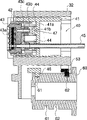
Fig. 5 is the profile of the schematic configuration of expression lid mechanism of this attending device and cam member.
Fig. 6 is about first cam path of this cam member and the camming movement curve map of second cam path.
Fig. 7 is the head mechanism of expression printer shown in Figure 1, the perspective view of the schematic configuration of lid mechanism and brush mechanism.
Fig. 8 is the plane of each mechanism shown in Figure 7.
Fig. 9 (a) and (b) are diagrams that the position of printhead and brush concerned during the cleaning that is illustrated in this form of implementation was handled.
Figure 10 (a)~(d) is the diagram of expression for the position relation of printhead and brush in the printhead cleaning processing of this form of implementation.
Figure 11 (a)~(c) is the diagram of expression for the position relation of printhead and brush in the brush cleaning processing of this form of implementation.
Figure 12 is the block diagram of expression printer control system shown in Figure 1.
The working of an invention form
Describe preferred implementing form with reference to the accompanying drawings in detail according to attending device of the present invention and printer equipped therewith.
Fig. 1 is the perspective view of the printer of expression a kind of form of implementation of the present invention.Fig. 2 is the perspective view that decomposes the schematic configuration of this printer of ground expression.Fig. 3 is the perspective view of the attending device of expression a kind of form of implementation of the present invention.Fig. 4 is the plane of attending device shown in Figure 3.Fig. 5 is the profile of the schematic configuration of the lid mechanism of expression attending device shown in Figure 4 and cam member.Fig. 6 is first cam path of this cam member and the camming movement curve map of second cam path.Fig. 7 is head mechanism, the lid mechanism of expression printer shown in Figure 1 and the perspective view of brushing the schematic configuration of mechanism.Fig. 8 is the plane of each mechanism shown in Figure 7.
As Fig. 1 or shown in Figure 2, the printer 1 of this form of implementation has the main body frame 2 that forms box shape, and printhead driving mechanism 10 is set on the middle body of this main body frame 2.Printhead driving mechanism 10 has the balladeur train axle 11 that extends along the length direction of main body frame 2, and balladeur train 17 is supported on this balladeur train axle 11 movably.
On balladeur train 17, be equipped with and roughly form block printhead 12.The nozzle face 15 that printhead 12 has a plurality of nozzles of alignment arrangements on its side, the place ahead (is shown in Fig. 7, Fig. 8), can optionally sprays middle printing ink via pipe 7 supplies from each nozzle.
Simultaneously, the balladeur train 17 that is mounted with this printhead 12 can move back and forth on balladeur train axle 11 by CD-ROM drive motor 13.
As Fig. 1 or shown in Figure 2, (Fig. 1,2 below part) is provided with ink cartridge 3 can be installed, the box retainer 5 of ink cartridge 4 on the part of the rear of main body frame 2.Here, in ink cartridge 3, fill the printing ink (for example black ink) of first kind of color.On the other hand, do not illustrate among the figure, ink cartridge 4 is divided into printing ink supply room and the discarded chamber of printing ink, fills the printing ink (for example red ink) of second kind of color in the printing ink supply room, fills the absorber that can absorb spent ink in the discarded chamber of printing ink.Simultaneously, when being installed on the ink cartridge retainer 5, middle the printing ink of first kind of color, second kind of color is supplied to printhead 12 from ink cartridge 3,4 to this ink cartridge 3,4 via pipe 7.
On the place ahead of main body frame 2 part (Fig. 1, the upper section of Fig. 2), paper guide 6 and paper feeding mechanism 20 are set.All than the short certain amount of the length of balladeur train axle 11, that is, the width length about equally of formation and record-paper is configured in the spatial portion office that separates certain distance with a sidepiece 2a of main body frame 2 for paper guide 6 and paper feeding mechanism 20.
Simultaneously, the structure of paper feeding mechanism 20 is, by CD-ROM drive motor 23 (shown in Figure 12) make feed roll 21 rotations with mounting on the platen of delivering on the paper guide 6 or by the record-paper of its guiding with printhead 12 subtends 22.
In addition, attending device 30 is arranged on the place ahead part of main body frame 2 to be embedded in the mode that is formed at the space segment between paper feeding mechanism 20 and the main body frame 2.Attending device 30 is equipped with L shaped substrate 31, is configured in the motor 71 on the substrate 31, pump 80, and lid mechanism 40, brush mechanism 50 is the transmission mechanism 70 of the transmission of power of motor 71 to each one 40,50,80.Simultaneously, lid mechanism 40 and brush mechanism 50 are configured between the sidepiece 2a of paper feeding mechanism 20 and main body frame 2, and on the other hand, both all are configured in transmission mechanism 70 and pump 80 between the bottom 2b of paper feeding mechanism 20 and main body frame 2.
And then, on substrate 31, being integrally formed the box-like support sector 32 of a part of opening, lid mechanism 40 and brush mechanism 50 are supported by support member 32.Simultaneously, when being assembled to printhead driving mechanism 10, paper feeding mechanism 20 and attending device 30 on the main body frame 2, the previous section of the platen 22 of paper feeding mechanism 20 becomes print area, and the previous section of the support portion 32 of supporting cover mechanism 40 and brush mechanism 50 becomes the maintenance area.Printhead 12 can move between these zones along balladeur train axle 11, and when being in print area, nozzle face 15 is in the face of platen 22, when the maintenance area, in the face of covering 43 or brush 52.
The transmission mechanism 70 of the transmission of power of motor 71 to each mechanism 40,50,80 is made of the gear row that a plurality of gears form, is rotated in the forward, its transmission of power to pump 80, by to opposite spin, is delivered in lid mechanism 40 and the brush mechanism 50 by motor 71.
On the back segment (near lid mechanism 40 and brush mechanism 50 sides) of the gear row that constitute transmission mechanism 70, be connected with druum cam 60.On the side of druum cam 60, be formed with independently respectively to be used to make and cover 43 cam paths 61 (first cam part) that slide, and the cam path 62 (second cam part) that makes brush 52 slip usefulness.This druum cam 60 also constitutes the part of brush mechanism 50 in a part that constitutes lid mechanism 40.The cam-follower 46 that cooperates with cam path 61 is set on the slide block 41 of lid mechanism 40, the cam-follower 53 that cooperates with cam path 62 is set on the slide block 51 of brush mechanism 50.Whereby, be accompanied by the rotation of druum cam 60, the slide block 51 of the slide block 41 of lid mechanism 40 and brush mechanism 50 is respectively along with cam path 61 and cam path 62 slide.
As shown in Figure 5, an end of the slide block 41 of lid mechanism 40 is openings, and the mid portion of portion forms isolation part 41a within it, further slidably slide block 41 is supported at the space segment inner cap retainer 42 of the front that is separated by it.Lid 43 is fixed on the fore-end that covers retainer 42.The box-shaped rubber with big opening that these lid 43 usefulness can be blocked the nozzle of printhead 12 forms, and the printing ink adsorbent 43a of sandwich construction is installed on its opening portion.
In addition, as shown in Figure 5, between lid 43 and slide block 41, be provided with by covering 43 valve systems 47 that carry out the switching of valve, it can be isolated the space in the lid 43 or be communicated with outside atmosphere with outside atmosphere.On lid 43 rear end part, the 43b of pipe portion that extends along lid retainer 42 glide directions is set, on the 43b of this pipe portion, run through the connected entrance 43c that is formed for making the space covered in 43 to be communicated with atmosphere.On the other hand, on the 41a of the isolation part of slide block 41 valve 41b is set highlightedly, it can contact with lid 43 the 43b of pipe portion and be used to stop up connected entrance 43c.And then, installation compression disc spring 44 between the valve 41b of lid 43 the 43b of pipe portion and slide block 41.In addition, the pipe 45 that is communicated with pump 80 is set on the rear end part of lid 43, compression disc spring 44 is being installed between lid 43 and slide block 41 around the pipe 45.
Simultaneously, carry out the switching of this connected entrance 43c by sliding slider 41, position by slide block 41, can the following any state of selectivity, promptly, be adjacent at lid 43 under the state of nozzle face of printhead 12 valve closing state (closed position), be close to the state of under the state of nozzle face valve being opened (hidden position) at lid 43, and cover 43 states (retreating position) that leave the nozzle face of printhead 43.
Under the situation of this form of implementation, as shown in Figure 6, closed position, the hidden position of lid 43 is in the position away from printhead 12 sides, and the distance of leaving its retreating position is respectively L1, L2 (<L1).When lid 43 was positioned at closed position, lid 43 was clamped between slide block 41 and the printhead just, and connected entrance 43C is closed by valve 41b.On the other hand, when lid 43 was in hidden position, lid 43 was loaded to printhead by compression disc spring 44, produced the gap that distance is L1-L2 between lid 43 and slide block 41, and connected entrance 43c becomes open mode.
Here, the shape of cam path 61 is decided by the relation of the slippage of the anglec of rotation of druum cam 60 and slide block 41.Simultaneously, on cam path 61, include a lid 43 and remain on closed position respectively, hidden position, three circular-arc cam path 61b of retreating position, 61c, 61a.That is, cam path 61 forms helical form on the surface of druum cam 60, but for its a part of cam path 61b, 61c, 61a, then the axle with respect to druum cam 60 forms vertical plane.Even druum cam 60 rotations, until rotation amount still rests on these positions above covering 43 before certain amount.
As shown in Figure 6, cover on 43 cam paths that move 61 making, in the scopes of 135 degree~290 degree, form lid 43 cam path 61a that remain on the retreating position in the anglec of rotation of druum cam 60.Simultaneously, the anglec of rotation at druum cam 60 forms the cam path 61b that lid 43 is remained on closed position in the scope of 350 degree~30 degree, and then, in the scopes of 45 degree~85 degree, form the cam path 61c that lid 43 is remained on hidden position in the anglec of rotation of druum cam 60.The cam path 61a that these are circular-arc, 61b, 61c couples together with spiral helicine cam path.
In addition, on the fore-end of slide block 41, the sticking department 41c of fixing printing head 12 usefulness is set.Whereby, keep printhead 12 and cover 43 certain position relations.
On the other hand, brush mechanism 50 has slide block 51 and brush 52 as shown in Figure 4.Slide block 51 is the casing shape, can the edge and the slide block 41 identical directions of lid mechanism 40 be slidably supported in support sector 32.On the fore-end of slide block 51, imbed the brush of making by rubber slab 52.Simultaneously, slide block 51 can move between following three positions, these positions are, brush 52 moves back to the most inboard position (retreating position) of attending device, dirt with 52 pairs of nozzle face 15 of brush carries out the printhead clear position (first wiping position) that usefulness is handled in wiping, and than the brush clear position (second wiping position) of more close printhead 12 sides of primary importance.As Figure 10, shown in 11, the printhead clear position is brush 52 a front end from the overhang of nozzle face 15 is the position that s1 moves to the printhead side, the brush clear position be an overhang be s2 (>s1) move to the position of printhead side.
Here, the shape of cam path 62 is the same with the slide block 41 of lid mechanism 40, is determined by the anglec of rotation of druum cam 60 and the relation of slide block 51 slippages.That is, as shown in Figure 6, on cam path 62, comprise brush 52 is remained on the printhead clear position respectively brush clear position, three circular-arc cam path 62a of retreating position, 62b, 62c.Each cam path 62a, 62b, 62c form the face vertical with respect to the axle of druum cam 60, even druum cam 60 rotations, before rotation amount surpassed certain amount, brush 52 still rested on these positions.
Under the situation of present embodiment, as shown in Figure 6, make on brush 52 cam paths that move 62, brush 52 is remained on the cam path 62c of retreating position in anglec of rotation formation in the scope of 270 degree~85 degree of druum cam 60.Simultaneously, the anglec of rotation at druum cam 60 forms the cam path 62a that brush 52 is remained on the printhead clear position in the scope of 135 degree~170 degree, and then, in being the scopes of 180 degree~200 degree, the anglec of rotation of druum cam 60 forms the cam path 62b that brush 52 is remained on the brush clear position.These circular-arc cam path 62a, 62b, 62c connects with the helical form cam path.
In addition, the pass between cam path 61 and the cam path 62 is to make that cover 43 advance and retreat synchronous in such a way with the advance and retreat of brushing 52.That is, when brush 52 was positioned at printhead clear position and brush clear position, lid 43 was maintained at retreating position, and on the other hand, when lid 43 was in closed position and hidden position, brush was maintained at retreating position.Lid 43 and brush 52 rotation that is accompanied by same druum cam 60 like this, mutually linkedly or close or away from printhead 12.
Under the situation of this form of implementation, as shown in Figure 6, in the scope of the cam path 61a that form to determine to cover 43 retreating position, just the anglec of rotation at druum cam 60 is in the scope of 135 degree~290 degree, set the printhead clear position of determining brush 52 and the cam path 62a that brushes clear position, 62b.On the other hand, in the scope of the cam path 62c that forms the retreating position of determining brush 52, promptly the anglec of rotation of druum cam 60 is in the scope of 270 degree~85 degree, is provided with and determines to cover 43 closed position, the cam path 61b of hidden position, 61c.
In addition, the detector 72 (being shown in Figure 12) that the initial position that detects druum cam 60 is used is set on substrate 31.In this form of implementation, in Fig. 6, the anglec of rotation that initial position is arranged on druum cam 60 is 60 positions when spending, by being that benchmark makes druum cam 60 rotations with this initial position, covers 43 and brush 52 Position Control.According to aforesaid form of implementation, by the cam path 61,62 of cam member 60, make and cover 43 and 52 slide linkedly respectively with brush, compared with prior art, can make the printer miniaturization and make mechanism simplification itself.
As shown in Figure 7, remover 56 is made basically the lamellar of " L shaped " by having the flexible metal of regulation, one end with the angle single arm type of regulation be supported on the side 12a of close side (maintenance area side) at one's side of printhead 12.On the end sections of the free section of remover 56, what be bending to the inside forms the 56a of the portion of striking off that uses to foreign matters such as removing printing ink on 52 from brushing hook-shapedly.Simultaneously, this strikes off the 56a of portion and can be clamped in brush 52 between the side 12a of it and printhead 12.
In addition, this strike off the 56a of portion be configured in respect to the nozzle 15 of printhead 12 after a while side (ink cartridge retainer side) by the position of below.Thereby, when printhead 12 when print zone moves, remover 56 not be positioned at platen 22 on record-paper contact.
On the other hand, on the position of the opposition side of the configuration cleaner 56 of printhead 12, use rear side with respect to nozzle face 15 to have the stepped of prescribed depth and be formed for from brushing the wiping portion 16 that wiping printing ink is used on 52 (second remover).By this wiping portion 16 is set, only just can remove to a certain extent attached to the foreign matter on the brush 52 by mobile print head 12, thereby, can reduce the cleaning processing frequency that makes the brush 52 that brush 52 moves, carries out with remover 56.
Figure 12 is the block diagram of the printer control system in this form of implementation of expression.As shown in figure 12, the printhead 12 of 55 pairs of printhead driving mechanisms 10 of control part and make printhead 12 move the motor 13 of usefulness, the motor 23 of paper feeding mechanism 20, the motor 71 of attending device 30 is controlled.These motors 13,23,71st, stepper motor, control part 55 give each motor 13,23,71 pulse signal, control each mechanism.Control part 55 is main by the microcomputer that is loaded on the circuit substrate, controls the ROM that the firmware of each mechanism and storage, execution firmware are used, RAM.
The rotation amount of control part 55 by control motor 13 prints 12 positions on the width of paper, simultaneously, and the anglec of rotation of the rotation amount control druum cam 60 by control motor 71.Detector 14 is arranged in the moving range of printhead 12, is used to detect the absolute position of printhead 12, and the Position Control of printhead 12 is as the criterion with the output of this detector 14 and carries out.On the other hand, the anglec of rotation of druum cam 60 is output as benchmark with detector 72 and controls, whereby, and the position of pilot brush 52, the position of lid 43.In addition, control part 55 also carries out lid 43 is being configured under the state that cover closed position simultaneously, attracts printing ink by making motor 71 be rotated in the forward driving pump 80 from printhead 12, and its printing ink that is sent to ink cartridge 4 is discarded control in the chamber.
Fig. 9 (a) and (b) are expression printheads for this form of implementation, the diagram of the position relation of printhead and brush when the brush cleaning is handled.Figure 10 (a)~(d) diagram that to be expression printhead when cleaning is handled for the printhead of this form of implementation, remover concern with the position of brush.Figure 11 (a)~(c) is a printhead when the brush cleaning of this form of implementation is handled, the diagram of the position relation of remover and brush.
In the maintaining method of this form of implementation, comprise the printhead cleaning processing of wiping attached to the foreign matters such as printing ink on the nozzle face 15 of printhead 12, strike off attached to the brush cleaning of the foreign matter on the brush 52 and handle, and in the nozzle of printhead 12, attract the nozzle of the obstruction of printing ink, prevention or elimination nozzle to attract to handle.In addition, for example during not printing processing, that is, when printhead 12 was in holding state, the lid 43 of lid mechanism 40 was in hidden position, and the brush 52 of brush mechanism 50 is handled retreating position.
At first, carrying out the occasion that nozzle attract to be handled, control part 55 moves to closed position to lid 43 from hidden position.That is, control part 55 makes the angle (spending from 60 degree → 10) of druum cam 60 rotation regulations in Fig. 6 with the umber of pulse CD-ROM drive motor 71 that is equivalent to its amount of movement.Then, the direction of rotation of switching motor 71, driving pump 80.At this moment, connected entrance 43c is in the state that is stopped up by sliding certainly 41 valve 41b, and the nozzle face of printhead 12 is airtight fully by lid 43, so by driving pump 80, the air pressure in the lid 43 reduces, from nozzle, attract printing ink, be discharged into through pipe 45 in the discarded chamber of printing ink of ink cartridge 4.
When the printhead 12 that is in holding state being printed head cleaning processing, at first, control part 55 moves to the printhead clear position S1 that surpasses s1 from the nozzle 15 outstanding amounts of printhead 12 to brush 52 from retreating position.That is, drive division 55 makes the angle (in Fig. 6, from 60 degree → 150 degree) of druum cam 60 rotation regulations to be equivalent to the umber of pulse CD-ROM drive motor 71 of its amount of movement.In addition, move to retreating position simultaneously by carrying out This move lid 43.
At this moment, the brush 52 that is in the printhead clear position is as Fig. 9 (a), shown in Figure 10 (a), is in the state with wiping portion 16 subtends of printhead 12.Then, control part 55 drives the umber of pulse of stipulating with the motor 13 of printhead driving mechanism 10, and printhead 12 is moved along the direction that enters print area from the servicing area.That is, make printhead 12 move to the brush cleaning starting position P2 shown in Fig. 9 (b) from the cleaning of printhead shown in Fig. 9 (a) starting position P1.
By moving of this printhead 12, brush 52 is with after the wiping portion 16 of printhead 12 contacts, and then shown in Figure 10 (b), slide on the nozzle face 15 of printhead 12 to have, by being removed on one's body transfer to 52 on brush attached to the printing ink on the nozzle face 15 9 corresponding to the amount of bow of overhang s1.In addition, even before sliding on the nozzle face 15, ink residue is arranged to brush 52, when brush 52 surmounts wiping portion 16, by this printing ink being clipped the printing ink of removing to a certain extent in the wiping portion 16 on the brush 52.
Then, printhead 12 is further to print area one side shifting, and shown in Figure 10 (c), brush 52 leaves the nozzle face 15 of printhead 12, stops at the 56a of the portion of the striking off position contacting P11 place with remover 56.The same with on nozzle face 15 time, brush 52 is in case of bending, contacts with the 56a of the portion of striking off of remover 56.
Then, shown in Figure 10 (d), control part 55 stops under the state of position P11 printhead 12, and brush 52 is moved to retreating position from printhead clear position S1.That is, control part 55 makes the angle (in Fig. 6, from 150 degree → 60 degree) of druum cam 60 rotation regulations to be equivalent to the umber of pulse CD-ROM drive motor 71 of its amount of movement.Then, when brush 52 directions to retreating position are moved, be maintained on the remover 56 from brushing that part of printing ink 9b that 52 front end length is approximately s1, be maintained on the brush 52 than that part of printing ink 9a that length is approximately the more close depths of s1 from brushing 52 front end.At this moment, owing to gently leave remover 56 and return to original state lentamente from case of bending by brushing 52, the printing ink 9a on the brush 52 is not intactly kept respectively with remover 9b with not dispersing.
On the other hand, brushing cleaning when handling, shown in Fig. 9 (b), when brush 52 moved to brush clear position S2, control part 55 stopped at printhead 12 to be held on the position (brush is cleared up starting position P2) between the side 12a of remover 56 and printhead 12.
Then, shown in Figure 11 (a), control part 55 moves to the brush clear position S2 that surpasses from the nozzle face 15 overhang s2 of printhead 12 to brush 52 from retreating position.That is, control part 55 makes the angle (among Fig. 6, from 60 degree → 190 degree) of druum cam 60 rotation regulations to be equivalent to the umber of pulse CD-ROM drive motor 71 of its amount of movement.Whereby, the fore-end of brush 52 surpasses the nozzle face 15 of printhead 12, enters between the side 12a of remover 56 and printhead 12.
Then, shown in Figure 11 (b), control part 55 drives the pulse of stipulating with the motor 13 of printhead driving mechanism 10, makes printhead 12 move to the position of the 56a of the portion of striking off with the brush 52 position contacting P21 of remover 56.Whereby, remover 56 has bending slightly.
Then, shown in Figure 11 (c), control part 55 CD-ROM drive motors 71, the angle (in Fig. 6, from 190 degree → 60 degree) that druum cam 60 rotations are stipulated makes brush 52 move to the direction of retreating position from brush clear position S2.By This move, 52 56a of the portion of striking off from remover 56 leave along with brush, and the 56a of the portion of striking off of remover 56 has and the corresponding elastic force of this amount of bow, will be that the part 9c of s2 strikes off attached to being equivalent to overhang among the printing ink 9c of brush on 52.
Like this, will brush 52 when brush clear position S2 turns back to retreating position, can make the printing ink 9d that remains on the brush 52 than brush 52 is remained in when printhead clear position S1 turns back to retreating position on the brush 52 printing ink 9a still less.That is, handle by carrying out the cleaning of this brush, in the process that the printhead cleaning of carrying out is next time handled, the state of the fore-end that can make brush 52 non-cohesive printing ink in the bigger scope of the part of employed overhang s1 when printing the head cleaning and handle.
Thereby, according to this form of implementation, when the nozzle face 15 of wiping printhead 12, by suitably striking off attached to the foreign matters such as printing ink on the brush 52 with remover 56, always can print the cleaning of head with the part of brush 52 non-cohesive printing ink, can prevent the spray nozzle clogging and the leak source of printhead 12.
Simultaneously, according to this form of implementation, the brush 52 after the nozzle face 15 of the intact printhead 12 of wiping is just intactly born by remover 56, so can prevent to splash attached to the printing ink on the brush 52.
In addition, in this form of implementation, enumerated that the cam part that makes the mobile usefulness of lid is illustrated at the example that the side of druum cam forms the groove shape, but also can form convex, constituted the cam surface that moves that limits brush, lid in the side of druum cam.
Claims (14)
1. an attending device is characterized by, and it is equipped with:
Make the reciprocating driving mechanism of the printhead with a plurality of nozzles;
Wiping is formed with the brush that dirt is used on the nozzle face of aforementioned nozzle;
The remover of plate body, the one end be single arm type be supported on stiff end on the aforementioned printhead sidepiece, its other end is the free end that forms the gap between the sidepiece of aforementioned printhead and aforementioned remover, is formed with the portion of striking off that can contact with aforementioned brush on aforementioned free end portion;
The driving mechanism that aforementioned brush is moved to aforementioned nozzle face direction from position of readiness; And
Control each driving mechanism, in that being stopped under the state of primary importance, aforementioned brush make aforementioned printhead move to the position that cooperates with aforementioned brush, utilize aforementioned brush to carry out the processing of dirt on the aforementioned nozzle face of wiping, and make aforementioned brush move to the position that cooperates with aforementioned remover, utilize aforementioned remover to carry out the aforementioned controlling organization that brushes the processing of dirt of wiping in that aforementioned printhead is stopped under the state of assigned position.
2. attending device as claimed in claim 1 is characterized by, and aforementioned controlling organization moves to the second place of more close printhead side to aforementioned brush from primary importance, carries out the aforementioned processing that brushes dirt of wiping.
3. attending device as claimed in claim 2, it is characterized by, aforementioned controlling organization makes aforementioned printhead move to the position that aforementioned brush cooperates with aforementioned remover under the state that aforementioned brush is stopped at the second place, aforementioned brush is moved to position of readiness, carry out the aforementioned processing that brushes dirt of wiping.
4. as any one described attending device in the claim 1 to 3, it is characterized by, aforementioned printhead can be at print area with in abutting connection with this print area, dispose between the maintenance area of aforementioned brush and move back and forth, and aforementioned remover is arranged on than the more close aforementioned maintenance area of the nozzle of aforementioned printhead one side.
5. as any one described attending device in the claim 1 to 3, it is characterized by, aforementioned remover is for having the flexible plate body of regulation.
6. attending device as claimed in claim 4 is characterized by, and aforementioned remover is for having the flexible plate body of regulation.
7. attending device as claimed in claim 1 is characterized by, and the portion of striking off of aforementioned remover is configured in from nozzle face and only withdraws on the position of ormal weight to printing first side.
8. as any one described attending device in the claim 1 to 3, it is characterized by, on the position of the opposition side of the aforementioned remover of configuration of aforementioned printhead, aforementioned second remover that brushes dirt of wiping is set.
9. an ink-jet printer is characterized by, and it is equipped with:
Make the reciprocating driving mechanism of the printhead with a plurality of nozzles;
Wiping is formed with the brush that dirt is used on the nozzle face of aforementioned nozzle;
The remover of plate body, the one end be single arm type be supported on stiff end on the aforementioned printhead sidepiece, its other end is the free end that forms the gap between the sidepiece of aforementioned printhead and aforementioned remover, is formed with the portion of striking off that can contact with aforementioned brush on aforementioned free end portion;
The driving mechanism that aforementioned brush is moved to aforementioned nozzle face direction from position of readiness; And
Control each driving mechanism, in that being stopped under the state of primary importance, aforementioned brush make aforementioned printhead move to the position that cooperates with aforementioned brush, utilize aforementioned brush to carry out the processing of dirt on the aforementioned nozzle face of wiping, and make aforementioned brush move to the position that cooperates with aforementioned remover, utilize aforementioned remover to carry out the aforementioned controlling organization that brushes the processing of dirt of wiping in that aforementioned printhead is stopped under the state of assigned position.
10. ink-jet printer as claimed in claim 9 is characterized by, and aforementioned controlling organization moves to the second place of more close printhead side to aforementioned brush from primary importance, carries out the aforementioned processing that brushes dirt of wiping.
11. ink-jet printer as claimed in claim 10, it is characterized by, aforementioned controlling organization makes aforementioned printhead move to the position that aforementioned brush cooperates with aforementioned remover under the state that aforementioned brush is stopped at the second place, aforementioned brush is moved to position of readiness, carry out the aforementioned processing that brushes dirt of wiping.
12. maintaining method, make the reciprocating driving mechanism of the printhead with a plurality of nozzles being equipped with, wiping is formed with the brush that dirt is used on the nozzle face of aforementioned nozzle, the remover of plate body, the one end be single arm type be supported on stiff end on the aforementioned printhead sidepiece, its other end is the free end that forms the gap between the sidepiece of aforementioned printhead and aforementioned remover, on aforementioned free end portion, be formed with the portion of striking off that can contact with aforementioned brush, make aforementioned brush from position of readiness to the maintaining method of the ink-jet printer of the driving mechanism that aforementioned nozzle face direction moves, it is characterized by, it has following operation:
Make aforementioned printhead move to the position that cooperates with aforementioned brush, utilize the operation of dirt on the aforementioned nozzle face of aforementioned brush wiping in that aforementioned brush is stopped under the state of primary importance,
Make aforementioned brush move to the position that cooperates with aforementioned remover, utilize the aforementioned operation that brushes dirt of aforementioned remover wiping in that aforementioned printhead is stopped under the state of assigned position.
13. maintaining method as claimed in claim 12 is characterized by, and carries out aforementioned brush is moved to the second place of more close printhead side, the aforementioned operation that brushes dirt of wiping from aforementioned primary importance.
14. maintaining method as claimed in claim 13, it is characterized by, further carry out under the state that aforementioned brush is stopped at the second place, making aforementioned printhead to move to the position that aforementioned brush cooperates with aforementioned remover, aforementioned brush is moved, the aforementioned operation that brushes dirt of wiping to position of readiness.
Applications Claiming Priority (6)
| Application Number | Priority Date | Filing Date | Title |
|---|---|---|---|
| JP2001123407 | 2001-04-20 | ||
| JP123407/01 | 2001-04-20 | ||
| JP123408/2001 | 2001-04-20 | ||
| JP123408/01 | 2001-04-20 | ||
| JP2001123408 | 2001-04-20 | ||
| JP123407/2001 | 2001-04-20 |
Publications (2)
| Publication Number | Publication Date |
|---|---|
| CN1382586A CN1382586A (en) | 2002-12-04 |
| CN1170683C true CN1170683C (en) | 2004-10-13 |
Family
ID=26613954
Family Applications (1)
| Application Number | Title | Priority Date | Filing Date |
|---|---|---|---|
| CNB021180253A Expired - Fee Related CN1170683C (en) | 2001-04-20 | 2002-04-19 | Maintenance appts. and maintenance method and ink-jet printer using same |
Country Status (6)
| Country | Link |
|---|---|
| US (2) | US6739696B2 (en) |
| EP (1) | EP1251007B1 (en) |
| KR (1) | KR100526492B1 (en) |
| CN (1) | CN1170683C (en) |
| AT (1) | ATE358020T1 (en) |
| DE (1) | DE60219098T2 (en) |
Families Citing this family (27)
| Publication number | Priority date | Publication date | Assignee | Title |
|---|---|---|---|---|
| EP1520704A4 (en) * | 2002-07-08 | 2010-02-24 | Seiko Epson Corp | Rotor, drive conversion device, cleaning device, wiping device, and liquid injection device |
| CN101054022B (en) * | 2002-07-08 | 2010-10-20 | 精工爱普生株式会社 | Rotor, drive converting apparatus, cleaning apparatus, wiping apparatus, and liquid ejection apparatus |
| NL1022595C2 (en) * | 2003-02-05 | 2004-08-06 | Oce Tech Bv | Cleaning device for the printhead of a printer. |
| US7140715B2 (en) * | 2003-06-13 | 2006-11-28 | Lexmark International, Inc. | Maintenance station for an imaging apparatus |
| US7621614B2 (en) * | 2003-08-15 | 2009-11-24 | Seiko Epson Corporation | Printing apparatus and printing system with a plurality of movable sensors for a plurality of features detection |
| JP2005193568A (en) * | 2004-01-08 | 2005-07-21 | Sony Corp | Nozzle cap, head cap unit, and liquid ejection head |
| US7448734B2 (en) * | 2004-01-21 | 2008-11-11 | Silverbrook Research Pty Ltd | Inkjet printer cartridge with pagewidth printhead |
| JP2005313606A (en) * | 2004-03-30 | 2005-11-10 | Seiko Epson Corp | Wiper cleaning device for liquid ejection device |
| JP2005319649A (en) * | 2004-05-07 | 2005-11-17 | Seiko Epson Corp | Head maintenance device and ink jet printer equipped with head maintenance device |
| US7390074B2 (en) * | 2004-05-07 | 2008-06-24 | Natsushita Electric Industrial Co., Ltd. | Methods of and apparatuses for wiping a line head in an ink jet recorder |
| US7188927B2 (en) * | 2004-09-16 | 2007-03-13 | Lexmark International, Inc. | Printhead wiper cleaning mechanism for an imaging apparatus |
| US7258416B2 (en) * | 2004-12-06 | 2007-08-21 | Silverbrook Research Pty Ltd | Inkjet printer with pivotal capping member |
| US6984017B1 (en) * | 2004-12-06 | 2006-01-10 | Silverbrook Research Pty Ltd | Inkjet printer incorporating a reel-to-reel flexible capping member |
| US7347526B2 (en) * | 2004-12-06 | 2008-03-25 | Silverbrook Research Pty Ltd | Capping member for inkjet printer |
| US7328968B2 (en) * | 2004-12-06 | 2008-02-12 | Silverbrook Research Pty Ltd | Inkjet printer with simplex printhead and capping/purging mechanism |
| US7393079B2 (en) * | 2004-12-21 | 2008-07-01 | Lexmark International, Inc. | Ink jet printhead garage configured to perform maintenance functions |
| EP1981716B1 (en) * | 2005-09-07 | 2011-11-09 | Retail Inkjet Solutions | System and method for refilling inkjet cartridges |
| JP5130961B2 (en) * | 2008-03-06 | 2013-01-30 | セイコーエプソン株式会社 | Inkjet printer head cleaning method |
| JP2010105306A (en) * | 2008-10-31 | 2010-05-13 | Brother Ind Ltd | Ink ejection device and its control method |
| JP5707354B2 (en) * | 2012-03-12 | 2015-04-30 | 東芝テック株式会社 | Image forming apparatus |
| WO2017142512A1 (en) * | 2016-02-16 | 2017-08-24 | Hewlett-Packard Development Company, L.P. | Page gap nozzle spitting |
| EP3390009B1 (en) | 2016-05-12 | 2022-02-16 | Hewlett-Packard Development Company, L.P. | Airflow component |
| JP6915298B2 (en) * | 2017-02-22 | 2021-08-04 | セイコーエプソン株式会社 | Liquid injection device and maintenance device |
| US11052662B2 (en) | 2019-12-06 | 2021-07-06 | Xerox Corporation | Inkjet printhead wiper cleaning system having cleaning fluid supplied brush |
| CN112046156A (en) * | 2020-09-24 | 2020-12-08 | 南通旭浩数码科技有限公司 | Ink-jet printing system |
| CN113844173A (en) * | 2021-08-10 | 2021-12-28 | 徐文强 | Printing electronic ink-jet printer |
| KR20230048826A (en) | 2021-10-05 | 2023-04-12 | 세메스 주식회사 | Substrate processing apparatus and maintenance method thereof |
Family Cites Families (15)
| Publication number | Priority date | Publication date | Assignee | Title |
|---|---|---|---|---|
| US4745414A (en) * | 1986-04-09 | 1988-05-17 | Canon Kabushiki Kaisha | Recovery device for an ink jet recorder and a recovery method thereof |
| DE69029780T2 (en) * | 1989-08-31 | 1997-07-10 | Canon Kk | Suction-regeneration device for an ink jet recording device |
| JP2872431B2 (en) | 1991-04-22 | 1999-03-17 | キヤノン株式会社 | Ink jet recording device |
| US5701146A (en) * | 1991-10-18 | 1997-12-23 | Canon Kabushiki Kaisha | Ink head recovery method and apparatus |
| DE69322459T2 (en) * | 1992-09-03 | 1999-06-02 | Canon Kk | Color beam recorder |
| JPH0839828A (en) | 1994-07-29 | 1996-02-13 | Canon Inc | Ink jet recording means and recording apparatus |
| EP0696506B1 (en) | 1994-08-12 | 2002-03-13 | Hewlett-Packard Company, A Delaware Corporation | Positioning of service station sled using motor driven CAm |
| US6132027A (en) | 1996-07-30 | 2000-10-17 | Fuji Xerox Co., Ltd. | Ink-jet type image forming apparatus |
| JPH1095127A (en) | 1996-07-30 | 1998-04-14 | Fuji Xerox Co Ltd | Image forming apparatus of ink-jet method |
| JP3536573B2 (en) * | 1997-03-13 | 2004-06-14 | ブラザー工業株式会社 | Inkjet printer recovery device |
| US6158840A (en) * | 1997-03-25 | 2000-12-12 | Seiko Epson Corporation | Ink jet recording apparatus |
| JPH10323988A (en) | 1997-03-25 | 1998-12-08 | Seiko Epson Corp | Ink jet recorder |
| US6151044A (en) | 1997-10-29 | 2000-11-21 | Hewlett-Packard Company | Hide-away wiper cleaner for inkjet printheads |
| JP4187120B2 (en) | 1998-11-06 | 2008-11-26 | 株式会社フレクストロニクス・デザイン・ジャパン | Inkjet printer head maintenance mechanism |
| JP2000141672A (en) | 1998-11-06 | 2000-05-23 | Fine Technol Kk | Method for cleaning head wiper of ink-jet printer |
-
2002
- 2002-04-19 AT AT02008260T patent/ATE358020T1/en not_active IP Right Cessation
- 2002-04-19 EP EP02008260A patent/EP1251007B1/en not_active Expired - Lifetime
- 2002-04-19 KR KR10-2002-0021478A patent/KR100526492B1/en not_active IP Right Cessation
- 2002-04-19 US US10/126,253 patent/US6739696B2/en not_active Expired - Fee Related
- 2002-04-19 CN CNB021180253A patent/CN1170683C/en not_active Expired - Fee Related
- 2002-04-19 DE DE60219098T patent/DE60219098T2/en not_active Expired - Lifetime
- 2002-04-22 US US10/127,264 patent/US6695430B2/en not_active Expired - Fee Related
Also Published As
| Publication number | Publication date |
|---|---|
| DE60219098D1 (en) | 2007-05-10 |
| ATE358020T1 (en) | 2007-04-15 |
| CN1382586A (en) | 2002-12-04 |
| KR100526492B1 (en) | 2005-11-08 |
| US20020175970A1 (en) | 2002-11-28 |
| KR20020082126A (en) | 2002-10-30 |
| US6739696B2 (en) | 2004-05-25 |
| DE60219098T2 (en) | 2007-08-16 |
| US6695430B2 (en) | 2004-02-24 |
| EP1251007B1 (en) | 2007-03-28 |
| US20020167562A1 (en) | 2002-11-14 |
| EP1251007A1 (en) | 2002-10-23 |
Similar Documents
| Publication | Publication Date | Title |
|---|---|---|
| CN1170683C (en) | Maintenance appts. and maintenance method and ink-jet printer using same | |
| US6916080B2 (en) | Cleaning device for cleaning printhead of ink-jet printer | |
| US20080143781A1 (en) | Inkjet printing apparatus and control method for inkjet printing apparatus | |
| CN100336665C (en) | Discharge recovery device and ink-jet recording apparatus | |
| US6631974B2 (en) | Ink jet recording apparatus having wiping mechanism | |
| EP0732212B1 (en) | Customized printhead servicing for different printer conditions | |
| US7740335B2 (en) | Liquid ejection apparatus and maintenance method of liquid ejection head | |
| KR100799005B1 (en) | Liquid ejection apparatus with liquid wiper device | |
| US6886907B1 (en) | Cleaning device for cleaning printhead of ink-jet printer | |
| JPH07205434A (en) | Fixed wiper blade assembly | |
| US20040041875A1 (en) | Ink jet recording apparatus | |
| US10105953B2 (en) | Cleaning device of liquid ejection head and liquid ejection device | |
| JPH08197741A (en) | Automatic positioning of wiper blade in ink jet printer maintenance station | |
| JPH06143592A (en) | Cap start mechanism for capping ink-jet print head | |
| WO1999061249A1 (en) | Ink jet printer equipped with maintenance system | |
| CN1974217A (en) | Inkjet image forming apparatus having a capping unit | |
| US20070159508A1 (en) | Wiper device and liquid ejection apparatus | |
| CN1182968C (en) | Ink-jet recording equipment and method for controlling & cleaning recording head in ink-jet recording equipment | |
| CN107053850A (en) | Ink-jet printer | |
| US7810900B2 (en) | Liquid ejection apparatus | |
| JP2007130806A (en) | Inkjet recorder | |
| JP2007130807A (en) | Inkjet recorder | |
| US11192376B2 (en) | Wiping assembly for liquid ejection head and ink jet printer | |
| US7726772B2 (en) | Liquid ejection apparatus | |
| JP3724449B2 (en) | Maintenance device, maintenance method, and inkjet printer using the same |
Legal Events
| Date | Code | Title | Description |
|---|---|---|---|
| C06 | Publication | ||
| PB01 | Publication | ||
| C10 | Entry into substantive examination | ||
| SE01 | Entry into force of request for substantive examination | ||
| C14 | Grant of patent or utility model | ||
| GR01 | Patent grant | ||
| REG | Reference to a national code |
Ref country code: HK Ref legal event code: WD Ref document number: 1051515 Country of ref document: HK |
|
| CF01 | Termination of patent right due to non-payment of annual fee | ||
| CF01 | Termination of patent right due to non-payment of annual fee |
Granted publication date: 20041013 Termination date: 20160419 |