CN116420120A - Control device - Google Patents
Control device Download PDFInfo
- Publication number
- CN116420120A CN116420120A CN202180075204.XA CN202180075204A CN116420120A CN 116420120 A CN116420120 A CN 116420120A CN 202180075204 A CN202180075204 A CN 202180075204A CN 116420120 A CN116420120 A CN 116420120A
- Authority
- CN
- China
- Prior art keywords
- display
- information
- information category
- divided
- displayed
- Prior art date
- Legal status (The legal status is an assumption and is not a legal conclusion. Google has not performed a legal analysis and makes no representation as to the accuracy of the status listed.)
- Pending
Links
- 238000010586 diagram Methods 0.000 description 7
- 230000006870 function Effects 0.000 description 4
- 238000000034 method Methods 0.000 description 4
- 238000004891 communication Methods 0.000 description 3
- 239000003595 mist Substances 0.000 description 2
- 230000002093 peripheral effect Effects 0.000 description 2
- 239000007787 solid Substances 0.000 description 2
- 230000001133 acceleration Effects 0.000 description 1
- 238000004364 calculation method Methods 0.000 description 1
- 230000000694 effects Effects 0.000 description 1
- 238000005516 engineering process Methods 0.000 description 1
- 238000009434 installation Methods 0.000 description 1
- 238000003754 machining Methods 0.000 description 1
- 238000012986 modification Methods 0.000 description 1
- 230000004048 modification Effects 0.000 description 1
- 230000003287 optical effect Effects 0.000 description 1
Images


Classifications
-
- G—PHYSICS
- G05—CONTROLLING; REGULATING
- G05B—CONTROL OR REGULATING SYSTEMS IN GENERAL; FUNCTIONAL ELEMENTS OF SUCH SYSTEMS; MONITORING OR TESTING ARRANGEMENTS FOR SUCH SYSTEMS OR ELEMENTS
- G05B19/00—Programme-control systems
- G05B19/02—Programme-control systems electric
- G05B19/18—Numerical control [NC], i.e. automatically operating machines, in particular machine tools, e.g. in a manufacturing environment, so as to execute positioning, movement or co-ordinated operations by means of programme data in numerical form
- G05B19/409—Numerical control [NC], i.e. automatically operating machines, in particular machine tools, e.g. in a manufacturing environment, so as to execute positioning, movement or co-ordinated operations by means of programme data in numerical form characterised by using manual data input [MDI] or by using control panel, e.g. controlling functions with the panel; characterised by control panel details or by setting parameters
-
- G—PHYSICS
- G06—COMPUTING; CALCULATING OR COUNTING
- G06F—ELECTRIC DIGITAL DATA PROCESSING
- G06F3/00—Input arrangements for transferring data to be processed into a form capable of being handled by the computer; Output arrangements for transferring data from processing unit to output unit, e.g. interface arrangements
- G06F3/01—Input arrangements or combined input and output arrangements for interaction between user and computer
- G06F3/048—Interaction techniques based on graphical user interfaces [GUI]
- G06F3/0481—Interaction techniques based on graphical user interfaces [GUI] based on specific properties of the displayed interaction object or a metaphor-based environment, e.g. interaction with desktop elements like windows or icons, or assisted by a cursor's changing behaviour or appearance
- G06F3/04817—Interaction techniques based on graphical user interfaces [GUI] based on specific properties of the displayed interaction object or a metaphor-based environment, e.g. interaction with desktop elements like windows or icons, or assisted by a cursor's changing behaviour or appearance using icons
-
- G—PHYSICS
- G06—COMPUTING; CALCULATING OR COUNTING
- G06F—ELECTRIC DIGITAL DATA PROCESSING
- G06F3/00—Input arrangements for transferring data to be processed into a form capable of being handled by the computer; Output arrangements for transferring data from processing unit to output unit, e.g. interface arrangements
- G06F3/01—Input arrangements or combined input and output arrangements for interaction between user and computer
- G06F3/048—Interaction techniques based on graphical user interfaces [GUI]
- G06F3/0481—Interaction techniques based on graphical user interfaces [GUI] based on specific properties of the displayed interaction object or a metaphor-based environment, e.g. interaction with desktop elements like windows or icons, or assisted by a cursor's changing behaviour or appearance
- G06F3/0482—Interaction with lists of selectable items, e.g. menus
-
- G—PHYSICS
- G06—COMPUTING; CALCULATING OR COUNTING
- G06F—ELECTRIC DIGITAL DATA PROCESSING
- G06F3/00—Input arrangements for transferring data to be processed into a form capable of being handled by the computer; Output arrangements for transferring data from processing unit to output unit, e.g. interface arrangements
- G06F3/01—Input arrangements or combined input and output arrangements for interaction between user and computer
- G06F3/048—Interaction techniques based on graphical user interfaces [GUI]
- G06F3/0487—Interaction techniques based on graphical user interfaces [GUI] using specific features provided by the input device, e.g. functions controlled by the rotation of a mouse with dual sensing arrangements, or of the nature of the input device, e.g. tap gestures based on pressure sensed by a digitiser
- G06F3/0488—Interaction techniques based on graphical user interfaces [GUI] using specific features provided by the input device, e.g. functions controlled by the rotation of a mouse with dual sensing arrangements, or of the nature of the input device, e.g. tap gestures based on pressure sensed by a digitiser using a touch-screen or digitiser, e.g. input of commands through traced gestures
- G06F3/04886—Interaction techniques based on graphical user interfaces [GUI] using specific features provided by the input device, e.g. functions controlled by the rotation of a mouse with dual sensing arrangements, or of the nature of the input device, e.g. tap gestures based on pressure sensed by a digitiser using a touch-screen or digitiser, e.g. input of commands through traced gestures by partitioning the display area of the touch-screen or the surface of the digitising tablet into independently controllable areas, e.g. virtual keyboards or menus
-
- G—PHYSICS
- G05—CONTROLLING; REGULATING
- G05B—CONTROL OR REGULATING SYSTEMS IN GENERAL; FUNCTIONAL ELEMENTS OF SUCH SYSTEMS; MONITORING OR TESTING ARRANGEMENTS FOR SUCH SYSTEMS OR ELEMENTS
- G05B2219/00—Program-control systems
- G05B2219/30—Nc systems
- G05B2219/32—Operator till task planning
- G05B2219/32128—Gui graphical user interface
-
- G—PHYSICS
- G05—CONTROLLING; REGULATING
- G05B—CONTROL OR REGULATING SYSTEMS IN GENERAL; FUNCTIONAL ELEMENTS OF SUCH SYSTEMS; MONITORING OR TESTING ARRANGEMENTS FOR SUCH SYSTEMS OR ELEMENTS
- G05B2219/00—Program-control systems
- G05B2219/30—Nc systems
- G05B2219/35—Nc in input of data, input till input file format
- G05B2219/35409—DPC direct programming at the console
-
- G—PHYSICS
- G06—COMPUTING; CALCULATING OR COUNTING
- G06F—ELECTRIC DIGITAL DATA PROCESSING
- G06F2203/00—Indexing scheme relating to G06F3/00 - G06F3/048
- G06F2203/048—Indexing scheme relating to G06F3/048
- G06F2203/04803—Split screen, i.e. subdividing the display area or the window area into separate subareas
Landscapes
- Engineering & Computer Science (AREA)
- General Engineering & Computer Science (AREA)
- Theoretical Computer Science (AREA)
- Human Computer Interaction (AREA)
- Physics & Mathematics (AREA)
- General Physics & Mathematics (AREA)
- Manufacturing & Machinery (AREA)
- Automation & Control Theory (AREA)
- User Interface Of Digital Computer (AREA)
- Programmable Controllers (AREA)
Abstract
The control device displays, for each of a plurality of divided regions in which the display screen is divided into a plurality of regions, a display information type selection screen in which a first display in which the position of the divided region on the display screen can be visually specified and a second display in which a list of information types that can be displayed in the divided regions are associated with each other to display the list. Then, a selection operation for the information category included in the second display is accepted, the information category displayed in the divided area is selected based on the selection operation, and information related to a predetermined information category is displayed in each of the plurality of divided areas based on the selection of the information category.
Description
Technical Field
The present invention relates to a control device.
Background
When an industrial machine such as a machine tool or a robot is operated, for example, when an operation is performed during an installation operation before machining, an operator performs the operation while checking different types of information. The control device for controlling an industrial machine has, for example, the following functions to be able to reference a plurality of different types of information on 1 screen: the display screen of the display device is divided into tile-shaped divided regions, and different types of information are displayed in each divided region (patent document 1, etc.).
However, there is a limit to the size and the number of pixels of a display screen of a display device. Therefore, particularly when it is necessary to display an amount of information that cannot be stored in 1 screen, such as a setting operation, it is necessary to perform an operation while switching information displayed in divided areas divided in the screen. Such switching of the display is performed by operating a vertical movement soft key, a horizontal movement soft key, a mechanical operation panel, or the like.
Prior art literature
Patent literature
Patent document 1: japanese patent laid-open No. 2000-066709
Disclosure of Invention
Problems to be solved by the invention
In this way, when a plurality of information categories are displayed while being switched for a plurality of divided areas, what information category can be displayed in each divided area is defined in advance, and the switching of the display is performed in accordance with the definition. However, if the vertical movement soft key, the horizontal movement soft key, the mechanical operation panel, or the like is operated to perform switching, it is difficult to grasp which information type is displayed in which divided area, and there is a problem that switching to the intended display is troublesome. In addition, in setting a job or the like, a job is often performed while comparing with a plurality of information categories. Therefore, in order to display the target information category in each of the plurality of divided areas, it is necessary to perform trial and error on the switching operation.
In order to cope with such a problem, it is desirable to be able to grasp the entire information type and to operate a means for switching what information type is displayed in each divided area.
Means for solving the problems
The control device of the present invention provides a user interface screen for selecting information types displayed for each divided area in a control device capable of dividing 1 display screen into a plurality of divided areas and displaying different information types for each divided area. On the screen, a list display of the positions of the divided regions on the display screen and the types of information that can be displayed in the divided regions is displayed in correspondence. By selecting the information category displayed in the predetermined divided area in the display, the display of the divided area is switched to the selected information category. The operator can grasp the information types that can be displayed in the divided areas at a glance, and can easily select a desired display mode.
Further, one aspect of the present invention is a control device capable of dividing 1 display screen into a plurality of divided regions, and displaying a display information category selection screen display unit that displays, for each of the plurality of divided regions, a first display that associates a position of the divided region on the display screen with a second display that indicates a list of information categories that can be displayed in the divided region, and performs a list display; a display information category selection unit that receives a selection operation for the information category included in the second display, and selects the information category displayed in the divided area according to the selection operation; and a display control section that displays information related to a predetermined information category in each of the plurality of divided areas based on the selection of the information category in the display information category selection section.
Effects of the invention
According to one aspect of the present invention, the information types that can be displayed in the respective divided areas can be displayed in a list, and the information types displayed in the respective divided areas can be freely selected, so that visibility for the operator is improved, the burden imposed on the work is reduced, and the operation time is reduced.
Drawings
Fig. 1 is a schematic hardware configuration diagram of a control device according to a first embodiment.
Fig. 2 is a schematic block diagram showing the function of the control device according to the first embodiment.
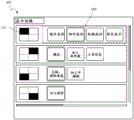
Fig. 3 is a diagram showing an example of a display information category selection screen.
Fig. 4 is a diagram showing another example of the display information category selection screen.
Fig. 5 is a diagram showing an example of a left-right 2-division display screen.
Detailed Description
Embodiments of the present invention will be described below with reference to the drawings.
Fig. 1 is a schematic hardware configuration diagram showing a main part of a control device according to a first embodiment of the present invention. The control device 1 of the present invention can be installed as a control device that controls the industrial machine 3 based on a control program, for example.
The CPU11 included in the control device 1 of the present embodiment is a processor that controls the entire control device 1. The CPU11 reads out a system program stored in the memory via the bus 22, and controls the entire control device 1 in accordance with the system program. The RAM13 temporarily stores temporary calculation data, display data, various data input from the outside, and the like.
The nonvolatile memory 14 is configured by, for example, a memory that is backed up by a battery (not shown), an SSD (Solid State Drive: solid state disk), or the like, and maintains a storage state even when the power supply of the control device 1 is turned off. The nonvolatile memory 14 stores control programs and data read from the external device 72 via the interface 15, control programs and data input from the input device 71 via the interface 18, and control programs and data acquired from other devices such as the mist computer 6 and the cloud server 7 via the network 5. The data stored in the nonvolatile memory 14 may include, for example, the position, speed, acceleration, load, and other data related to each physical quantity detected by a sensor (not shown) attached to the industrial machine 3, of each motor provided in the industrial machine 3. The control program and data stored in the nonvolatile memory 14 may be developed in the RAM13 at the time of execution and/or use. Various system programs such as a well-known analysis program are written in advance in the ROM 12.
The interface 15 is an interface for connecting the CPU11 of the control device 1 and an external device 72 such as an external storage medium. For example, a control program, setting data, and the like used for controlling the industrial machine 3 are read from the external device 72 side. The control program, setting data, and the like edited in the control device 1 can be stored in an external storage medium (not shown) such as a CF card or a USB memory via the external device 72. A Programmable Logic Controller (PLC) 16 executes a ladder diagram program, and outputs signals to and controls the industrial machine 3 and peripheral devices (for example, an actuator such as a tool changer and a robot, and a sensor such as a temperature sensor and a humidity sensor attached to the industrial machine 3) of the industrial machine 3 via an I/O unit 19. Signals of various switches, peripheral devices, and the like, which are provided in an operation panel of the main body of the industrial machine 3, are received, subjected to necessary signal processing, and then transferred to the CPU11.
The interface 20 is an interface for connecting the CPU11 of the control apparatus 1 to the wired or wireless network 5. The network 5 may communicate using, for example, serial communication such as RS-485, ethernet (registered trademark) communication, optical communication, wireless LAN, wi-Fi (registered trademark), bluetooth (registered trademark), or other technologies. The network 5 is connected to a higher-level management device such as another machine, the mist computer 6, the cloud server 7, and the like, and exchanges data with the control device 1.
The display device 70 outputs and displays data read into a memory, data obtained as a result of executing a program or the like, and the like via the interface 17. The display device 70 is preferably capable of acquiring information (e.g., display size, number of pixels, etc.) related to the display capability from the control device 1. The acquired information on the display capability may be acquired sequentially or may be stored in the RAM13 or the nonvolatile memory 14 as in other information. The input device 71, which is constituted by a keyboard, a pointing device, or the like, transmits instructions, data, or the like based on an operation performed by an operator, to the CPU11 via the interface 18.
The shaft control circuit 30 for controlling the shaft provided in the industrial machine 3 receives the movement command amount of the shaft from the CPU11, and outputs the shaft command to the servo amplifier 40. The servo amplifier 40 receives the command and drives the servo motor 50 for moving the drive unit of the industrial machine 3 along the axis. The shaft servo motor 50 has a position/speed detector built therein, and position/speed feedback signals from the position/speed detector are fed back to the shaft control circuit 30, respectively, to perform feedback control of the position/speed. In the hardware configuration of fig. 1, only 1 shaft control circuit 30, servo amplifier 40, and servo motor 50 are shown, but the number of shafts of the industrial machine 3 to be controlled is actually prepared.
Fig. 2 is a diagram schematically showing functions of the control device 1 according to the first embodiment of the present invention. The functions of the control device 1 according to the present embodiment are realized by the CPU11 of the control device 1 shown in fig. 1 executing a system program and controlling the operations of the respective units of the control device 1.
The control device 1 of the present embodiment includes a display control unit 100, a display information type selection screen display unit 110, a display information type selection unit 120, and a division mode specification unit 130. The RAM13 or nonvolatile memory 14 of the control device 1 is provided with: an information category storage unit 200 that stores at least information for identifying information categories that can be displayed by the control device 1 (for example, names of information categories, pointers to display programs for displaying information related to the information categories, and the like); a divided area display information category storage unit 210 that associates and stores information categories that are assigned to the divided areas and that can be displayed for each divided area; and a division pattern storage unit 220 that is an area in which a division pattern indicating how to divide the display screen of the display device 70 is stored in advance.
The display control unit 100 is realized by the CPU11 of the control device 1 shown in fig. 1 executing a system program read from the ROM12, and mainly by the CPU11 performing an arithmetic process using the RAM13 and the nonvolatile memory 14 and a display output process using the interface 17. The display control unit 100 divides the display screen of the display device 70 into a plurality of divided areas, and displays information related to the specified information category in each divided area. When displaying information related to the information category, the display control unit 100 refers to the information category storage unit 200 and calls out a display program corresponding to the information category to be displayed. The display control unit 100 generally treats the display screen of the display device 70 as 1 display area, and displays information related to a predetermined information category determined by an operation of an operator on the display area. When division of the display screen is designated by the division pattern designating unit 130, the display control unit 100 divides the display screen into a plurality of divided areas based on the designated division pattern division. Then, information related to the predetermined information category stored in the divided area display information category storage unit 210 is displayed in each divided area.
The display information type selection screen display 110 is realized by the CPU11 of the control device 1 shown in fig. 1 executing a system program read from the ROM12, and is mainly realized by the CPU11 performing an arithmetic process using the RAM13 and the nonvolatile memory 14 and a display output process via the interface 17. The display information category selection screen display unit 110 displays a display information category selection screen on the display screen of the display device 70.
Fig. 3 shows an example of a display information category selection screen. Fig. 3 shows an example of a division pattern in which a display screen is divided into 4 divided areas, i.e., left and right 2 divided areas and up and down 2 divided areas, and displayed.
The display information category selection screen 300 includes at least a first display 310 capable of visually determining the position of each divided region on the display screen. The first display 310 may also be a display capable of visually determining the size of each divided region on the display screen. In the example of fig. 3, the entire display screen is divided by a dividing line (broken line), and the first display 310 is represented as an icon in which the position of the divided region on the display screen is darkened.
The display information type selection screen 300 includes at least a second display 320 showing a list of information types that can be displayed in each divided area. The second display 320 may be highlighted so that the information type currently displayed in the corresponding divided area can be grasped. The second display 320 may be highlighted so that the information category selected recently can be grasped as in the case of the display in the divided area. In the example of fig. 3, the second display 320 is presented in the form of an icon displaying the name of the information category.
In each divided area, as shown in fig. 3, the display of the icon is highlighted by 2-frame, so that the "relative coordinates" is displayed on the upper left, the "modes" is displayed on the upper right, the "main axis and feed speed" are displayed on the lower left, and the information related to the information category of the "machining program" is displayed on the lower right. The first display 310 and the second display 320 corresponding to the same divided region are displayed so that the correspondence relationship thereof can be grasped. The first display 310 and the second display 320 are displayed based on the correspondence between each divided area stored in the divided area display information category storage unit 210 and the information category assigned to the divided area. For example, in the example of fig. 3, the first display 310 and the second display 320 corresponding to the same divided area are displayed in the same row in a laterally aligned manner. In this example, the information categories of "absolute coordinates", "relative coordinates", "mechanical coordinates", "integrated display" can be displayed in the upper left divided region. In this way, in the display information type selection screen, it is configured that which information type can be displayed in which divided area can be grasped at a glance.
The display information type selection unit 120 is realized by the CPU11 of the control device 1 shown in fig. 1 executing the system program read from the ROM12, and by the CPU11 mainly performing arithmetic processing using the RAM13 and the nonvolatile memory 14 and input/output processing via the interfaces 17 and 18. The display information type selection unit 120 receives a selection operation for the second display 320, and determines a list of information types displayed in each divided area based on the selection operation.
In the display information category selection screen 300 illustrated in fig. 3, each information category included in the second display 320 is configured to be selectable, for example, in the same second display 320 as a radio button. When the operator operates a mouse or the like to select the information category included in the second display 320, the display information category selection unit 120 changes the information category selected by the operator to the highlighted display, and changes the information category that was originally highlighted to the normal display. Then, the display information type selection unit 120 instructs the display control unit 100 to display the divided area corresponding to the second display in which the operator has performed the selection operation as the information type selected in the selection operation. In addition, when the division mode to which the division area corresponding to the second display in which the operator has performed the selection operation belongs is different from the division mode currently displayed, the display information type selection unit 120 instructs the division mode designation unit 130 to change to the division mode to which the selected division area belongs.
The division mode designating unit 130 is realized by the CPU11 included in the control device 1 shown in fig. 1 executing the system program read out from the ROM12, and by the CPU11 mainly performing arithmetic processing using the RAM13 and the nonvolatile memory 14. The division mode designating unit 130 designates a division mode indicating how to divide the display screen of the display device 70 based on an instruction from the display information type selecting unit 120.
Fig. 4 shows an example of a display information category selection screen including a first display and a second display corresponding to a plurality of division modes. As illustrated in fig. 4, when display is performed in the split mode in which the display screen is split into left and right 2 split and up and down 2 split, the display information type selection screen is displayed. At this time, when the information category displayed in the divided region belonging to the division mode of the left-right 2 division different from the division mode currently displayed is selected from the display information category selection screen, the display information category selection section 120 instructs the division mode designation section 130 to change the display of the division mode of the left-right 2 division. The division pattern specification unit 130 receives the instruction and reads out the specified division pattern from the division pattern storage unit 220. Then, the instruction display control unit 100 displays the result in the read division mode. Upon receiving this instruction, the display control unit 100 switches to the display in which the split mode is changed, as illustrated in fig. 5.
The control device 1 having the above-described configuration can display the information types that can be displayed in each divided area in a list, and can freely select the information types displayed in each divided area, so that the visibility of the operator is improved, the burden on the work is reduced, and the operation time is reduced. In particular, by grasping the position of each divided area on the display screen and the information type displayed in each divided area at a glance, when a plurality of information types are displayed while being switched as in the case of setting a job or the like and the plurality of information types having relevance are displayed in an aligned manner according to the situation, the relationship between the position of the divided area in which the job can be performed efficiently and the information type that can be displayed can be organized.
While the embodiment of the present invention has been described above, the present invention is not limited to the example of the embodiment described above, and can be implemented in various modes by applying appropriate modifications.
Description of the reference numerals
1 control device
3 Industrial machine
5 network
6 fog computer
7 cloud server
11CPU
12ROM
13RAM
14 non-volatile memory
15 17, 18, 20 interfaces
16PLC
19I/O unit
22 bus
30-axis control circuit
40 servo amplifier
50 servo motor
70 display device
71 input device
72 external device
100 display control unit
110 display section for displaying information category selection screen
120 display information category selection unit
130 division mode designating unit
200 information category storage unit
210 divided area display information category storage unit
220 division pattern storage unit.
Claims (4)
1. A control device capable of dividing a display screen into a plurality of divided areas, characterized in that,
a display information category selection screen display unit that displays, for each of a plurality of divided areas, a display information category selection screen in which a first display that can visually identify the position of the divided area on the display screen and a second display that represents a list of information categories that can be displayed in the divided area are associated with each other to display the list;
a display information category selection unit that receives a selection operation for the information category included in the second display, and selects the information category displayed in the divided area based on the selection operation; and
and a display control unit that displays information related to a predetermined information category in each of the plurality of divided areas based on the selection of the information category in the display information category selection unit.
2. The control device according to claim 1, wherein,
the control device further includes a division mode specification unit that specifies a division mode of the display screen based on selection of the information category in the display information category selection unit,
the display control unit divides the display screen into a plurality of divided areas based on the division pattern specified by the division pattern specification unit.
3. The control device according to claim 1, wherein,
the first display is an icon display indicating a position of the divided region on the display screen.
4. The control device according to claim 1, wherein,
the second display is highlighted by the display control unit so that the information type displayed in the divided area can be grasped.
Applications Claiming Priority (3)
| Application Number | Priority Date | Filing Date | Title |
|---|---|---|---|
| JP2020193517 | 2020-11-20 | ||
| JP2020-193517 | 2020-11-20 | ||
| PCT/JP2021/042261 WO2022107818A1 (en) | 2020-11-20 | 2021-11-17 | Control device |
Publications (1)
| Publication Number | Publication Date |
|---|---|
| CN116420120A true CN116420120A (en) | 2023-07-11 |
Family
ID=81708989
Family Applications (1)
| Application Number | Title | Priority Date | Filing Date |
|---|---|---|---|
| CN202180075204.XA Pending CN116420120A (en) | 2020-11-20 | 2021-11-17 | Control device |
Country Status (5)
| Country | Link |
|---|---|
| US (1) | US20230409004A1 (en) |
| JP (1) | JPWO2022107818A1 (en) |
| CN (1) | CN116420120A (en) |
| DE (1) | DE112021004864T5 (en) |
| WO (1) | WO2022107818A1 (en) |
Family Cites Families (3)
| Publication number | Priority date | Publication date | Assignee | Title |
|---|---|---|---|---|
| JP4105303B2 (en) | 1998-08-20 | 2008-06-25 | 株式会社森精機製作所 | Display device for NC machine tools |
| JP2010120095A (en) * | 2008-11-17 | 2010-06-03 | Yaskawa Electric Corp | Robot system |
| WO2015194010A1 (en) * | 2014-06-19 | 2015-12-23 | 株式会社牧野フライス製作所 | Control device for machine tool |
-
2021
- 2021-11-17 CN CN202180075204.XA patent/CN116420120A/en active Pending
- 2021-11-17 US US18/035,183 patent/US20230409004A1/en active Pending
- 2021-11-17 JP JP2022563805A patent/JPWO2022107818A1/ja active Pending
- 2021-11-17 WO PCT/JP2021/042261 patent/WO2022107818A1/en active Application Filing
- 2021-11-17 DE DE112021004864.3T patent/DE112021004864T5/en active Pending
Also Published As
| Publication number | Publication date |
|---|---|
| US20230409004A1 (en) | 2023-12-21 |
| DE112021004864T5 (en) | 2023-08-03 |
| JPWO2022107818A1 (en) | 2022-05-27 |
| WO2022107818A1 (en) | 2022-05-27 |
Similar Documents
| Publication | Publication Date | Title |
|---|---|---|
| US8190287B2 (en) | Tool vector display apparatus for a machine tool with rotational axes | |
| CN107422694B (en) | Control panel for a machine tool and management system for a machine tool | |
| WO2012102472A1 (en) | Apparatus and method for inputting cutting shape using interactive program in computer numerical control machine tool | |
| CN111142475A (en) | Information processing apparatus | |
| CN105938411B (en) | Control panel | |
| EP0816959B1 (en) | Compact numerical controller | |
| CN111610754A (en) | Picture creation device and picture creation system | |
| CN112147949B (en) | Parameter management device and management system thereof | |
| JP6638979B2 (en) | Numerical control device with machining process management function and machining process management program | |
| JP2010287034A (en) | Address display system of modbus protocol communication between external equipment and plc | |
| CN116420120A (en) | Control device | |
| WO2022107822A9 (en) | Controller | |
| JP2006285496A (en) | Programmable display unit, display control program and recording medium with the program recorded thereon | |
| CN111324088B (en) | Information processing apparatus | |
| EP0455817A1 (en) | Three-dimensional cursor and off-line programming system using the same | |
| JP4381793B2 (en) | PROGRAMMABLE DISPLAY, DISPLAY CONTROL PROGRAM, RECORDING MEDIUM RECORDING THE PROGRAM, SCREEN CREATION DEVICE, SCREEN CREATION PROGRAM, AND RECORDING MEDIUM RECORDING THE PROGRAM | |
| JP3079973U (en) | Composition of machine monitor screen | |
| EP0578828A1 (en) | Screen display method for cnc | |
| WO2023228327A1 (en) | Control device | |
| JPH0242510A (en) | Display system for working information | |
| JP4372739B2 (en) | PROGRAMMABLE DISPLAY, CONTROL PROGRAM, RECORDING MEDIUM RECORDING THE PROGRAM, SCREEN CREATION DEVICE, SCREEN CREATION PROGRAM, AND RECORDING MEDIUM RECORDING THE PROGRAM | |
| CN107615196B (en) | Numerical control device and display control method | |
| JP2559273B2 (en) | Numerical control device and screen display method of numerical control device | |
| JPH09120308A (en) | Tool path plotting method | |
| JP2005122584A (en) | Nc program editing apparatus |
Legal Events
| Date | Code | Title | Description |
|---|---|---|---|
| PB01 | Publication | ||
| PB01 | Publication | ||
| SE01 | Entry into force of request for substantive examination | ||
| SE01 | Entry into force of request for substantive examination |