CN116210204A - System and method for VLAN switching and routing services - Google Patents
System and method for VLAN switching and routing services Download PDFInfo
- Publication number
- CN116210204A CN116210204A CN202180061266.5A CN202180061266A CN116210204A CN 116210204 A CN116210204 A CN 116210204A CN 202180061266 A CN202180061266 A CN 202180061266A CN 116210204 A CN116210204 A CN 116210204A
- Authority
- CN
- China
- Prior art keywords
- packet
- network
- vsrs
- instance
- address
- Prior art date
- Legal status (The legal status is an assumption and is not a legal conclusion. Google has not performed a legal analysis and makes no representation as to the accuracy of the status listed.)
- Pending
Links
Images


Classifications
-
- H—ELECTRICITY
- H04—ELECTRIC COMMUNICATION TECHNIQUE
- H04L—TRANSMISSION OF DIGITAL INFORMATION, e.g. TELEGRAPHIC COMMUNICATION
- H04L45/00—Routing or path finding of packets in data switching networks
- H04L45/58—Association of routers
- H04L45/586—Association of routers of virtual routers
-
- G—PHYSICS
- G06—COMPUTING; CALCULATING OR COUNTING
- G06F—ELECTRIC DIGITAL DATA PROCESSING
- G06F9/00—Arrangements for program control, e.g. control units
- G06F9/06—Arrangements for program control, e.g. control units using stored programs, i.e. using an internal store of processing equipment to receive or retain programs
- G06F9/44—Arrangements for executing specific programs
- G06F9/455—Emulation; Interpretation; Software simulation, e.g. virtualisation or emulation of application or operating system execution engines
- G06F9/45533—Hypervisors; Virtual machine monitors
- G06F9/45558—Hypervisor-specific management and integration aspects
-
- H—ELECTRICITY
- H04—ELECTRIC COMMUNICATION TECHNIQUE
- H04L—TRANSMISSION OF DIGITAL INFORMATION, e.g. TELEGRAPHIC COMMUNICATION
- H04L12/00—Data switching networks
- H04L12/28—Data switching networks characterised by path configuration, e.g. LAN [Local Area Networks] or WAN [Wide Area Networks]
-
- H—ELECTRICITY
- H04—ELECTRIC COMMUNICATION TECHNIQUE
- H04L—TRANSMISSION OF DIGITAL INFORMATION, e.g. TELEGRAPHIC COMMUNICATION
- H04L12/00—Data switching networks
- H04L12/28—Data switching networks characterised by path configuration, e.g. LAN [Local Area Networks] or WAN [Wide Area Networks]
- H04L12/46—Interconnection of networks
- H04L12/4641—Virtual LANs, VLANs, e.g. virtual private networks [VPN]
-
- H—ELECTRICITY
- H04—ELECTRIC COMMUNICATION TECHNIQUE
- H04L—TRANSMISSION OF DIGITAL INFORMATION, e.g. TELEGRAPHIC COMMUNICATION
- H04L45/00—Routing or path finding of packets in data switching networks
- H04L45/02—Topology update or discovery
-
- H—ELECTRICITY
- H04—ELECTRIC COMMUNICATION TECHNIQUE
- H04L—TRANSMISSION OF DIGITAL INFORMATION, e.g. TELEGRAPHIC COMMUNICATION
- H04L45/00—Routing or path finding of packets in data switching networks
- H04L45/38—Flow based routing
-
- H—ELECTRICITY
- H04—ELECTRIC COMMUNICATION TECHNIQUE
- H04L—TRANSMISSION OF DIGITAL INFORMATION, e.g. TELEGRAPHIC COMMUNICATION
- H04L45/00—Routing or path finding of packets in data switching networks
- H04L45/54—Organization of routing tables
-
- H—ELECTRICITY
- H04—ELECTRIC COMMUNICATION TECHNIQUE
- H04L—TRANSMISSION OF DIGITAL INFORMATION, e.g. TELEGRAPHIC COMMUNICATION
- H04L45/00—Routing or path finding of packets in data switching networks
- H04L45/66—Layer 2 routing, e.g. in Ethernet based MAN's
-
- H—ELECTRICITY
- H04—ELECTRIC COMMUNICATION TECHNIQUE
- H04L—TRANSMISSION OF DIGITAL INFORMATION, e.g. TELEGRAPHIC COMMUNICATION
- H04L45/00—Routing or path finding of packets in data switching networks
- H04L45/74—Address processing for routing
- H04L45/745—Address table lookup; Address filtering
-
- H—ELECTRICITY
- H04—ELECTRIC COMMUNICATION TECHNIQUE
- H04L—TRANSMISSION OF DIGITAL INFORMATION, e.g. TELEGRAPHIC COMMUNICATION
- H04L47/00—Traffic control in data switching networks
- H04L47/10—Flow control; Congestion control
- H04L47/12—Avoiding congestion; Recovering from congestion
- H04L47/125—Avoiding congestion; Recovering from congestion by balancing the load, e.g. traffic engineering
-
- H—ELECTRICITY
- H04—ELECTRIC COMMUNICATION TECHNIQUE
- H04L—TRANSMISSION OF DIGITAL INFORMATION, e.g. TELEGRAPHIC COMMUNICATION
- H04L47/00—Traffic control in data switching networks
- H04L47/10—Flow control; Congestion control
- H04L47/18—End to end
-
- H—ELECTRICITY
- H04—ELECTRIC COMMUNICATION TECHNIQUE
- H04L—TRANSMISSION OF DIGITAL INFORMATION, e.g. TELEGRAPHIC COMMUNICATION
- H04L47/00—Traffic control in data switching networks
- H04L47/70—Admission control; Resource allocation
- H04L47/78—Architectures of resource allocation
- H04L47/783—Distributed allocation of resources, e.g. bandwidth brokers
-
- H—ELECTRICITY
- H04—ELECTRIC COMMUNICATION TECHNIQUE
- H04L—TRANSMISSION OF DIGITAL INFORMATION, e.g. TELEGRAPHIC COMMUNICATION
- H04L49/00—Packet switching elements
- H04L49/70—Virtual switches
-
- H—ELECTRICITY
- H04—ELECTRIC COMMUNICATION TECHNIQUE
- H04L—TRANSMISSION OF DIGITAL INFORMATION, e.g. TELEGRAPHIC COMMUNICATION
- H04L61/00—Network arrangements, protocols or services for addressing or naming
- H04L61/09—Mapping addresses
- H04L61/10—Mapping addresses of different types
- H04L61/103—Mapping addresses of different types across network layers, e.g. resolution of network layer into physical layer addresses or address resolution protocol [ARP]
-
- H—ELECTRICITY
- H04—ELECTRIC COMMUNICATION TECHNIQUE
- H04L—TRANSMISSION OF DIGITAL INFORMATION, e.g. TELEGRAPHIC COMMUNICATION
- H04L61/00—Network arrangements, protocols or services for addressing or naming
- H04L61/45—Network directories; Name-to-address mapping
- H04L61/4552—Lookup mechanisms between a plurality of directories; Synchronisation of directories, e.g. metadirectories
-
- H—ELECTRICITY
- H04—ELECTRIC COMMUNICATION TECHNIQUE
- H04L—TRANSMISSION OF DIGITAL INFORMATION, e.g. TELEGRAPHIC COMMUNICATION
- H04L63/00—Network architectures or network communication protocols for network security
- H04L63/10—Network architectures or network communication protocols for network security for controlling access to devices or network resources
- H04L63/101—Access control lists [ACL]
-
- H—ELECTRICITY
- H04—ELECTRIC COMMUNICATION TECHNIQUE
- H04L—TRANSMISSION OF DIGITAL INFORMATION, e.g. TELEGRAPHIC COMMUNICATION
- H04L63/00—Network architectures or network communication protocols for network security
- H04L63/16—Implementing security features at a particular protocol layer
- H04L63/166—Implementing security features at a particular protocol layer at the transport layer
-
- G—PHYSICS
- G06—COMPUTING; CALCULATING OR COUNTING
- G06F—ELECTRIC DIGITAL DATA PROCESSING
- G06F9/00—Arrangements for program control, e.g. control units
- G06F9/06—Arrangements for program control, e.g. control units using stored programs, i.e. using an internal store of processing equipment to receive or retain programs
- G06F9/44—Arrangements for executing specific programs
- G06F9/455—Emulation; Interpretation; Software simulation, e.g. virtualisation or emulation of application or operating system execution engines
- G06F9/45533—Hypervisors; Virtual machine monitors
- G06F9/45558—Hypervisor-specific management and integration aspects
- G06F2009/45595—Network integration; Enabling network access in virtual machine instances
-
- H—ELECTRICITY
- H04—ELECTRIC COMMUNICATION TECHNIQUE
- H04L—TRANSMISSION OF DIGITAL INFORMATION, e.g. TELEGRAPHIC COMMUNICATION
- H04L2101/00—Indexing scheme associated with group H04L61/00
- H04L2101/60—Types of network addresses
- H04L2101/618—Details of network addresses
- H04L2101/622—Layer-2 addresses, e.g. medium access control [MAC] addresses
-
- H—ELECTRICITY
- H04—ELECTRIC COMMUNICATION TECHNIQUE
- H04L—TRANSMISSION OF DIGITAL INFORMATION, e.g. TELEGRAPHIC COMMUNICATION
- H04L67/00—Network arrangements or protocols for supporting network services or applications
- H04L67/01—Protocols
- H04L67/10—Protocols in which an application is distributed across nodes in the network
Landscapes
- Engineering & Computer Science (AREA)
- Computer Networks & Wireless Communication (AREA)
- Signal Processing (AREA)
- Computer Security & Cryptography (AREA)
- General Engineering & Computer Science (AREA)
- Software Systems (AREA)
- Computer Hardware Design (AREA)
- Computing Systems (AREA)
- Theoretical Computer Science (AREA)
- Physics & Mathematics (AREA)
- General Physics & Mathematics (AREA)
- Data Exchanges In Wide-Area Networks (AREA)
Abstract
Systems and methods for VLAN Switching and Routing Services (VSRS) are disclosed herein. A method may include generating a table for an instance of a VSRS coupling a first virtual layer 2network (VLAN) with a second network. The table may contain information identifying the IP address, MAC address, and virtual interface identifier of the instance in the virtual layer 2 network. The method may include receiving, with a VSRS, a packet from a first instance, the packet designated for delivery to a second instance within the virtual layer 2network, identifying, with the VSRS, the second instance within the virtual layer 2network to deliver the packet based on information received with the packet and information contained within the table, and delivering the packet to the identified second instance.
Description
Cross Reference to Related Applications
The application claims the benefit of:
(1) U.S. provisional application No.63/051,728, filed on 7.14/2020, entitled "VLAN Switching And Routing Service And Layer-2Networking In A Virtualized Cloud Environment", and
(2) U.S. provisional application No.63/132,377, filed 12/30/2020, entitled "Layer-2 Networking In A Virtualized Cloud Environment". The entire contents of the above provisional application are incorporated herein by reference for all purposes.
This application is also related to U.S. application No. __________________ (Attorney Docket No.088325-1203134-276500 US) entitled "VIRTUAL LAYER-2NETWORK" filed on 7.14.2021, and to U.S. application No. __________________ (Attorney Docket No.088325-1256549-276520 US) entitled "INTERFACE-BASED ACLS IN A LAYER-2NETWORK" filed on 7.14.2021, the entire contents of each of which are incorporated herein by reference for all purposes.
Background
Cloud computing provides on-demand availability of computing resources. Cloud computing may be based on a data center accessible to users via the internet. Cloud computing may provide infrastructure as a service (IaaS). A virtual network may be created for use by a user. However, these virtual networks have limitations that limit their functionality and value. Thus, further improvements are desired.
Disclosure of Invention
One aspect of the present disclosure relates to a computer-implemented method. The method includes providing a virtual layer 3 network in a virtualized cloud environment and providing a virtual layer 2network in the virtualized cloud environment, the virtual layer 3 network hosted by an underlying physical network, the virtual layer 2network hosted by the underlying physical network.
In some embodiments, the virtual layer 2 network may be a Virtual Local Area Network (VLAN). In some embodiments, a VLAN includes a plurality of endpoints. In some embodiments, the plurality of endpoints may be a plurality of computing instances. In some embodiments, a VLAN includes a plurality of L2 virtual network interface cards (L2 VNICs) and a plurality of switches.
In some embodiments, each of the plurality of computing instances is communicatively coupled with a pair comprising a unique L2 virtual network interface card (L2 VNIC) and a unique switch. In some embodiments, multiple switches together may form a distributed switch. In some embodiments, each of the plurality of switches routes outbound traffic according to a mapping table received from an L2VNIC paired with the switch. In some embodiments, the mapping table identifies interface-to-MAC address mappings for endpoints within a VLAN.
In some embodiments, the method further includes instantiating, on a Network Virtualization Device (NVD), a pair including the unique L2VNIC and the unique switch. In some embodiments, the method includes receiving, from another endpoint within the VLAN, a packet addressed to one of the plurality of computing instances at a unique L2VNIC of the one of the plurality of computing instances, and learning a mapping of the other endpoint with the unique L2VNIC of the one of the plurality of computing instances. In some embodiments, the mapping of the other endpoint includes an interface-to-MAC address mapping of the other endpoint.
In some embodiments, the method includes decapsulating the received packet with a unique L2VNIC of one of the plurality of computing instances and forwarding the decapsulated packet to the one of the plurality of computing instances. In some embodiments, the method includes learning an IP address to MAC address mapping of the other endpoint with one of the plurality of computing instances.
In some embodiments, the method includes sending an IP packet from a first computing instance in the VLAN, the IP packet including a destination IP address of a second computing instance in the VLAN, receiving the IP packet at a first L2VNIC associated with the first computing instance, encapsulating the IP packet at the first L2VNIC, and forwarding the IP packet to the second computing instance via the first switch. In some embodiments, the first switch and the first L2VNIC are used together for a pair communicatively coupled with the first computing instance. In some embodiments, the method further includes receiving the IP packet at a second VNIC, the second VNIC being associated with a second computing instance, decapsulating the IP packet at the second VNIC, and forwarding the IP packet from the second VNIC to the second computing instance.
In some embodiments, the virtual layer 2 network includes a plurality of Virtual Local Area Networks (VLANs). In some embodiments, each of the plurality of VLANs includes a plurality of endpoints. In some embodiments, the plurality of VLANs includes a first VLAN and a second VLAN. In some embodiments, the first VLAN includes a plurality of first endpoints and the second VLAN includes a plurality of second endpoints. In some embodiments, each of the plurality of VLANs has a unique identifier. In some embodiments, one of the plurality of first endpoints in the first VLAN communicates with one of the plurality of second endpoints in the second VLAN.
One aspect of the present disclosure relates to a system including a physical network. The physical network includes at least one host machine and at least one network virtualization device. The physical network may provide a virtual layer 3 network in the virtualized cloud environment and a virtual layer 2 network in the virtualized cloud environment, the virtual layer 3 network hosted by the underlying physical network, the virtual layer 2 network hosted by the underlying physical network.
One aspect of the disclosure relates to a non-transitory computer-readable storage medium storing a plurality of instructions executable by one or more processors. The plurality of instructions, when executed by the one or more processors, cause the one or more processors to provide a virtual layer 3 network in the virtualized cloud environment and a virtual layer 2 network in the virtualized cloud environment, the virtual layer 3 network hosted by an underlying physical network, the virtual layer 2 network hosted by the underlying physical network.
One aspect of the present disclosure relates to a method comprising generating a table for an instance of a VLAN Switching and Routing Service (VSRS) that couples a first virtual layer 2 network with a second network. In some embodiments, the table contains information identifying an IP address, a MAC address, and a virtual interface identifier of an instance within the first virtual layer 2 network. The method includes receiving, with the VSRS, a packet from the first instance designated for delivery to a second instance in the first virtual layer 2 network, identifying the second instance in the first virtual layer 2 network with the VSRS to deliver the packet based on information received with the packet and information contained in the table, and delivering the packet to the identified second instance.
In some embodiments, the first virtual layer 2 network includes a plurality of instances. In some embodiments, the first virtual layer 2 network includes a plurality of L2 virtual network interface cards (L2 VNICs) and a plurality of switches. In some embodiments, each of the plurality of instances is communicatively coupled with a pair comprising a unique L2 virtual network interface card (L2 VNIC) and a unique switch.
In some embodiments, identifying, with the VSRS, a second instance for delivering the packet within the first virtual layer 2 network based on the information received with the packet and the information contained in the table includes determining, with the VSRS, that the table does not include mapping information for the second instance, suspending, with the VSRS, delivery of the packet, broadcasting, with the VSRS, an ARP request to an L2 VNIC in the first virtual layer 2 network, the ARP request including an IP address of the second instance, and receiving, with the VSRS, an ARP response from the L2 VNIC of the second instance.
In some embodiments, the method further comprises updating the table based on the received ARP response. In some embodiments, the first instance is external to the first virtual layer 2 network and in the second network. In some embodiments, the second network may be an L3 network. In some embodiments, the second network may be a second virtual layer 2 network. In some embodiments, the table is generated based on communications received by the VSRS.
In some embodiments, the method includes instantiating the VSRS as a service on a plurality of hardware nodes. In some embodiments, the method includes distributing the table across hardware nodes. In some embodiments, a table distributed across hardware nodes may be accessed by another VSRS instantiation. In some embodiments, the first instance is internal to the first virtual layer 2 network.
In some embodiments, the method includes receiving, with the VSRS, a packet from a third instance inside the first virtual layer 2 network. In some embodiments, the packet is designated for delivery to a fourth instance external to the first virtual layer 2 network and the packet is forwarded to the fourth instance. In some embodiments, the method includes receiving, with the VSRS, a packet from a third instance inside the first virtual layer 2 network. In some embodiments, the packet is designated for delivery to a service used by a third instance within the first virtual layer 2 network. In some embodiments, the service may be at least one of: DHCP; NTP; and DNS.
In some embodiments, the method includes receiving, with the VSRS, a packet from a third instance inside the first virtual layer 2 network. In some embodiments, the packet is designated for delivery to a fourth instance in the virtual layer 2 network. In some embodiments, the method includes distributing a table of instances of the VSRS with layer 2 and layer 3 network information across a set of service nodes to provide highly reliable and highly scalable instantiation of the VSRS. In some embodiments, the method includes receiving a packet with a VSRS from a third instance within the first virtual layer 2 network, and learning a mapping of the third instance with the VSRS.
One aspect of the present disclosure relates to a system. The system includes a physical network. The physical network includes at least one processor and a network virtualization device. The at least one processor may instantiate an instance of a VLAN Switching and Routing Service (VSRS) that couples the first virtual layer 2 network with the second network and generates a table for the instance of the VSRS. In some embodiments, the table contains information identifying an IP address, a MAC address, and a virtual interface identifier of an instance within the first virtual layer 2 network. The at least one processor may receive packets from the first instance designated for delivery to a second instance within the first virtual layer 2 network with the VSRS, identify the second instance within the first virtual layer 2 network with the VSRS to deliver the packets based on information received with the packets and information contained in the table, and deliver the packets to the identified second instance.
One aspect of the disclosure relates to a non-transitory computer-readable storage medium storing a plurality of instructions executable by one or more processors. The plurality of instructions, when executed by the one or more processors, cause the one or more processors to: instances of VLAN Switching and Routing Services (VSRS) are instantiated, which couple the first virtual layer 2 network with the second network and generate tables for the instances of the VSRS. In some embodiments, the table contains information identifying an IP address, a MAC address, and a virtual interface identifier for an instance within the first virtual layer 2 network. The one or more processors are configured to execute the one or more processors with the plurality of instructions: a packet designated for delivery to a second instance within the first virtual layer 2 network is received from the first instance with the VSRS, the second instance within the first virtual layer 2 network is identified with the VSRS to deliver the packet based on information received with the packet and information contained in the table, and the packet is delivered to the identified second instance.
One aspect of the present disclosure relates to a method. The method comprises the following steps: transmitting the packet from a source computing instance to a destination computing instance in the virtual network via a destination L2 virtual network interface card (destination L2 VNIC) in the first virtual layer 2 network, evaluating an Access Control List (ACL) for the packet having the source virtual network interface card (source VNIC), embedding ACL information related to the packet in the packet, forwarding the encapsulated packet to a Virtual Switching and Routing Service (VSRS) that couples the first virtual layer 2 network (VLAN) with the second network, identifying the destination L2 VNIC within the first virtual layer 2 network with the VSRS to deliver the packet based on information received with the packet and mapping information contained in the mapping table, accessing the ACL information from the packet with the VSRS, and applying the accessed ACL information to the packet.
In some embodiments, the packets comprise IP packets. In some embodiments, the source computing instance is located in a virtual L3 network. In some embodiments, the source computing instance is located in a second virtual layer 2 network.
In some embodiments, the method includes encapsulating the packet with a source VNIC. In some embodiments, the method includes receiving and decapsulating the packet with the VSRS. In some embodiments, identifying, with the VSRS, a destination L2 VNIC within the first virtual layer 2 network to deliver the packet based on the information received with the packet and the mapping information contained in the mapping table includes determining, with the VSRS, that the mapping table does not include the mapping information for the destination computing instance, suspending VSRS forwarding of the packet, broadcasting, with the VSRS, an ARP request to the L2 VNIC in the first virtual layer 2 network, the ARP request including an IP address of the destination computing instance, and receiving, with the VSRS, an ARP response from the L2 VNIC of the destination computing instance. In some embodiments, one of the L2 VNICs is an L2 VNIC of the destination computing instance.
In some embodiments, the method includes updating the table based on the received ARP response. In some embodiments, identifying, with the VSRS, a destination L2 VNIC within the first virtual layer 2 network to deliver the packet based on the information received with the packet and the mapping information contained in the mapping table includes determining that the mapping table includes the mapping information for the destination computing instance, and identifying the destination L2 VNIC based on the mapping information contained in the mapping table. In some embodiments, embedding the ACL information associated with the packet in the packet includes storing the ACL information as metadata in the packet. In some embodiments, accessing ACL information from the packet with the VSRS includes extracting metadata in the packet that contains ACL information.
In some embodiments, applying the accessed ACL information to the packet includes determining that the ACL information is independent of the destination L2 VNIC. In some embodiments, applying the accessed ACL information to the packet further includes forwarding the packet to a destination computing instance via the destination L2 VNIC. In some embodiments, applying the accessed ACL information to the packet includes determining, with the VSRS, that the ACL information is relevant to the destination L2 VNIC. In some embodiments, applying the accessed ACL information to the packet further includes: determining, with the VSRS, that the destination L2 VNIC complies with ACL information; and forwarding the packet with the VSRS to the destination computing instance via the destination L2 VNIC.
In some embodiments, applying the accessed ACL information to the packet further includes: determining, with the VSRS, that the destination L2 VNIC does not comply with the ACL information; the VSRS discards the packet. In some embodiments, applying the accessed ACL information to the packet further includes sending a response to the source computing instance with the VSRS indicating the dropping of the packet.
One aspect of the present disclosure relates to a system including a physical network. The physical network includes at least one first processor, a network virtualization device, and at least one second processor. The at least one processor may send a packet from a source computing instance in a virtual network instantiated on the physical network to a destination computing instance via a destination L2 virtual network interface card (destination L2 VNIC) within a first virtual layer 2 network instantiated on the physical network. The network virtualization device may instantiate a source VNIC. The source VNIC may evaluate an Access Control List (ACL) for the packet, embed ACL information related to the packet in the packet, and forward the packet to a Virtual Switching and Routing Service (VSRS) that couples the first virtual layer 2 network (VLAN) with the second network. The at least one second processor may instantiate a VSRS. The VSRS may identify the destination L2 VNIC to deliver the packet based on information received with the packet and mapping information contained in the mapping table, access ACL information from the packet, and apply the accessed ACL information to the packet.
In some embodiments, applying the accessed ACL information to the packet includes determining that the ACL information is associated with the destination L2 VNIC, determining that the destination L2 VNIC conforms to the ACL information, and forwarding the packet with the VSRS to the destination computing instance via the destination L2 VNIC.
One aspect of the disclosure relates to a non-transitory computer-readable storage medium storing a plurality of instructions executable by one or more processors. The method includes, when executed by one or more processors, causing the one or more processors to send a packet from a source computing instance to a destination computing instance in a virtual network via a destination L2 virtual network interface card (destination L2 VNIC) in a first virtual layer 2 network, evaluating an Access Control List (ACL) for the packet with the source virtual network interface card (source VNIC), embedding ACL information associated with the packet in the packet, forwarding the packet to a Virtual Switching and Routing Service (VSRS) that couples the first virtual layer 2 network (VLAN) to a second network, identifying the destination L2 VNIC within the first virtual layer 2 network with the VSRS based on information received with the packet and mapping information contained in a mapping table to deliver the packet, accessing the ACL information from the packet with the VSRS; and applies the accessed ACL information to the packet.
Drawings
FIG. 1 is a high-level diagram of a distributed environment, illustrating a virtual or overlay cloud network hosted by a cloud service provider infrastructure, according to some embodiments.
Fig. 2 depicts a simplified architectural diagram of physical components in a physical network within a CSPI, in accordance with some embodiments.
FIG. 3 illustrates an example arrangement within a CSPI in which a host machine is connected to multiple Network Virtualization Devices (NVDs), in accordance with certain embodiments.
FIG. 4 depicts connectivity between a host machine and an NVD for providing I/O virtualization to support multi-tenancy (NVD) in accordance with certain embodiments.
Fig. 5 depicts a simplified block diagram of a physical network provided by a CSPI, in accordance with some embodiments.
FIG. 6 is a schematic diagram of one embodiment of a computing network.
Fig. 7 is a logic and hardware schematic of a Virtual Local Area Network (VLAN).
Fig. 8 is a logical schematic of a plurality of connected L2 VLANs.
Fig. 9 is a logical schematic of a plurality of connected L2 VLANs and subnets.
Figure 10 is a schematic diagram of one embodiment of intra-VLAN communication and learning within a VLAN.
Fig. 11 is a schematic diagram of an example of an implementation view of a VLAN.
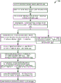
Figure 12 is a flow chart illustrating one embodiment of a process for intra-VLAN communication.
Fig. 13 is a schematic diagram of a process for intra-VLAN communication.
Figure 14 is a flow chart illustrating one embodiment of a process for inter-VLAN communication in a virtual L2 network.
Fig. 15 is a schematic diagram of a process for inter-VLAN communication.
Figure 16 is a flow chart illustrating one embodiment of a process for ingress packet flow.
Fig. 17 is a schematic diagram of a process for portal communication.
Figure 18 is a flow chart illustrating one embodiment of a process for egress packet flow from a VLAN.
Fig. 19 is a schematic diagram of a process for egress packet flow.
FIG. 20 is a flow chart illustrating one embodiment of a process for deferred Access Control List (ACL) classification.
FIG. 21 is a flow chart illustrating one embodiment of a process for early classification of ACLs.
Fig. 22 is a flow chart illustrating one embodiment of a process for sender-based next hop routing.
Fig. 23 is a flow chart illustrating one embodiment of a process for delayed next hop routing.
Fig. 24 is a block diagram illustrating one mode for implementing cloud infrastructure as a service system in accordance with at least one embodiment.
Fig. 25 is a block diagram illustrating another mode for implementing a cloud infrastructure as a service system in accordance with at least one embodiment.
Fig. 26 is a block diagram illustrating another mode for implementing cloud infrastructure as a service system in accordance with at least one embodiment.
Fig. 27 is a block diagram illustrating another mode for implementing a cloud infrastructure as a service system in accordance with at least one embodiment.
FIG. 28 is a block diagram illustrating an example computer system in accordance with at least one embodiment.
Detailed Description
In the following description, for purposes of explanation, specific details are set forth in order to provide a thorough understanding of certain embodiments. It may be evident, however, that the various embodiments may be practiced without these specific details. The drawings and description are not intended to be limiting. The word "exemplary" is used herein to mean "serving as an example, instance, or illustration. Any embodiment or design described herein as "exemplary" is not necessarily to be construed as preferred or advantageous over other embodiments or designs.
Example virtual networking architecture
The term cloud service is generally used to refer to services provided by a Cloud Service Provider (CSP) to users or customers on demand (e.g., via a subscription model) using systems and infrastructure (cloud infrastructure) provided by the CSP. Typically, the servers and systems that make up the P infrastructure of the CS are separate from the client's own in-house deployment servers and systems. Thus, customers can utilize cloud services provided by CSPs without purchasing separate hardware and software resources for the services. Cloud services are designed to provide subscribing customers with simple, extensible access to applications and computing resources without requiring the customers to invest in purchasing infrastructure for providing the services.
There are several cloud service providers that offer various types of cloud services. There are various different types or models of cloud services, including software as a service (SaaS), platform as a service (PaaS), infrastructure as a service (IaaS), and the like.
A customer may subscribe to one or more cloud services provided by the CSP. The customer may be any entity, such as an individual, organization, business, etc. When a customer subscribes to or registers for a service provided by the CSP, a lease or account will be created for the customer. The customer may then access one or more cloud resources of the subscription associated with the account via this account.
As described above, infrastructure as a service (IaaS) is a specific type of cloud computing service. In the IaaS model, CSPs provide infrastructure (referred to as cloud service provider infrastructure or CSPI) that can be used by customers to build their own customizable networks and deploy customer resources. Thus, the customer's resources and network are hosted in a distributed environment by the CSP's provided infrastructure. This is in contrast to traditional computing, where the customer's resources and network are hosted by the customer's provided infrastructure.
The CSPI may include high performance computing resources, including various host machines, memory resources, and network resources, that form an interconnection of a physical network, also referred to as a baseboard network or an underlay network. Resources in the CSPI may be spread over one or more data centers, which may be geographically spread over one or more geographic regions. Virtualization software may be executed by these physical resources to provide a virtualized distributed environment. Virtualization creates an overlay network (also referred to as a software-based network, a software-defined network, or a virtual network) on a physical network. The CSPI physical network provides an underlying foundation for creating one or more overlay or virtual networks over the physical network. The physical network (or substrate network or underlay network) includes physical network devices such as physical switches, routers, computers, and host machines. An overlay network is a logical (or virtual) network that runs on top of a physical substrate network. A given physical network may support one or more overlay networks. Overlay networks typically use encapsulation techniques to distinguish traffic belonging to different overlay networks. Virtual or overlay networks are also known as Virtual Cloud Networks (VCNs). Virtual networks are layers of network abstraction that are implemented using software virtualization technology (e.g., hypervisors, virtualized functions implemented by Network Virtualization Devices (NVDs) (e.g., intelligent network cards), top-of-rack (TOR) switches, intelligent TORs that implement one or more functions performed by NVDs, and other mechanisms) to create a network that can run over a physical network. Virtual networks may take many forms, including peer-to-peer networks, IP networks, and the like. The virtual network is typically either a layer 3IP network or a layer 2VLAN. This method of virtual or overlay networking is often referred to as a virtual or overlay 3 network. Examples of protocols developed for virtual networks include IP-in-IP (or Generic Routing Encapsulation (GRE)), virtual extensible local area networks (VXLAN-IETF RFC 7348), virtual Private Networks (VPNs) (e.g., MPLS layer 3 virtual private network (RFC 4364)), NSX of VMware, GENEVE, and the like.
For IaaS, the infrastructure provided by CSP (CSPI) may be configured to provide virtualized computing resources over a public network (e.g., the internet). In the IaaS model, cloud computing service providers may host infrastructure components (e.g., servers, storage devices, network nodes (e.g., hardware), deployment software, platform virtualization (e.g., hypervisor layer), etc.). In some cases, the IaaS provider may also offer various services to accompany those infrastructure components (e.g., billing, monitoring, logging, security, load balancing, clustering, etc.). Thus, as these services may be policy driven, iaaS users may be able to implement policies to drive load balancing to maintain application availability and performance. CSPI provides a collection of infrastructure and complementary cloud services that enable customers to build and run a wide range of applications and services in a highly available hosted distributed environment. CSPI provides high performance computing resources and capabilities as well as storage capacity in flexible virtual networks that are securely accessible from a variety of networking locations, such as from a customer's in-house deployment network. When a customer subscribes to or registers for an IaaS service provided by the CSP, the lease created for that customer is a secure and sequestered partition within the CSPI in which the customer can create, organize and manage their cloud resources.
Customers may build their own virtual network using the computing, memory, and networking resources provided by the CSPI. One or more customer resources or workloads, such as computing instances, may be deployed on these virtual networks. For example, a customer may use resources provided by the CSPI to build one or more customizable and private virtual networks, referred to as Virtual Cloud Networks (VCNs). A customer may deploy one or more customer resources, such as computing instances, on a customer VCN. The computing instances may take the form of virtual machines, bare metal instances, and the like. Thus, CSPI provides a collection of infrastructure and complementary cloud services that enable customers to build and run a wide range of applications and services in a highly available virtual hosted environment. Clients do not manage or control the underlying physical resources provided by the CSPI, but may control the operating system, storage devices, and deployed applications; and may have limited control over selected networking components (e.g., firewalls).
CSP may provide a console that enables clients and network administrators to use CSPI resources to configure, access, and manage resources deployed in the cloud. In some embodiments, the console provides a web-based user interface that may be used to access and manage the CSPI. In some implementations, the console is a web-based application provided by the CSP.
The CSPI may support single-lease or multi-lease architectures. In a single tenancy architecture, software (e.g., applications, databases) or hardware components (e.g., host machines or servers) serve a single customer or tenant. In a multi-tenancy architecture, software or hardware components serve multiple customers or tenants. Thus, in a multi-tenancy architecture, the CSPI resources are shared among multiple customers or tenants. In the multi-tenancy case, precautions are taken and safeguards are implemented in the CSPI to ensure that each tenant's data is isolated and remains invisible to other tenants.
In a physical network, a network endpoint (endpoint) refers to a computing device or system that connects to and communicates back and forth with the physical network to which it is connected. Network endpoints in a physical network may be connected to a Local Area Network (LAN), wide Area Network (WAN), or other type of physical network. Examples of traditional endpoints in a physical network include modems, hubs, bridges, switches, routers and other network devices, physical computers (or host machines), and the like. Each physical device in the physical network has a fixed network address that can be used to communicate with the device. This fixed network address may be a layer 2 address (e.g., MAC address), a fixed layer 3 address (e.g., IP address), etc. In a virtualized environment or virtual network, endpoints may include various virtual endpoints, such as virtual machines hosted by components of a physical network (e.g., by physical host machines). These endpoints in the virtual network are addressed by overlay addresses, such as overlay 2 addresses (e.g., overlay MAC addresses) and overlay 3 addresses (e.g., overlay IP addresses). Network coverage enables flexibility by allowing a network administrator to move around an overlay address associated with a network endpoint using software management (e.g., via software implementing a control plane for a virtual network). Thus, unlike a physical network, in a virtual network, an overlay address (e.g., an overlay IP address) may be moved from one endpoint to another endpoint using network management software. Because the virtual network builds on top of the physical network, communication between components in the virtual network involves the virtual network and the underlying physical network. To facilitate such communications, components of the CSPI are configured to learn and store mappings that map overlay addresses in the virtual network to actual physical addresses in the baseboard network, and vice versa. These mappings are then used to facilitate communications. Customer traffic is encapsulated to facilitate routing in the virtual network.
Thus, a physical address (e.g., a physical IP address) is associated with a component in the physical network, and an overlay address (e.g., an overlay IP address) is associated with an entity in the virtual or overlay network. The physical IP address is an IP address associated with a physical device (e.g., a network device) in the substrate or physical network. For example, each NVD has an associated physical IP address. The overlay IP address is an overlay address associated with an entity in the overlay network, such as with a computing instance in a Virtual Cloud Network (VCN) of a customer. Two different customers or tenants each having their own private VCN can potentially use the same overlay IP address in their VCN without being aware of each other. Both the physical IP address and the overlay IP address are types of real IP addresses. These are separate from the virtual IP address. The virtual IP address is typically a single IP address that represents or maps to multiple real IP addresses. The virtual IP address provides a one-to-many mapping between the virtual IP address and a plurality of real IP addresses. For example, the load balancer may use VIP to map or represent multiple servers, each with its own real IP address.
The cloud infrastructure or CSPI is physically hosted in one or more data centers in one or more regions of the world. The CSPI may include components in a physical or substrate network and virtualized components located in a virtual network built upon the physical network components (e.g., virtual networks, computing instances, virtual machines, etc.). In certain embodiments, the CSPI is organized and hosted in the domain, region, and availability domains. A region is typically a localized geographic area containing one or more data centers. Regions are generally independent of each other and can be far apart, e.g., across countries or even continents. For example, a first region may be in australia, another in japan, another in india, etc. The CSPI resources are divided between regions such that each region has its own independent subset of CSPI resources. Each region may provide a set of core infrastructure services and resources, such as computing resources (e.g., bare machine servers, virtual machines, containers, and related infrastructure, etc.); storage resources (e.g., block volume storage, file storage, object storage, archive storage); network resources (e.g., virtual Cloud Network (VCN), load balancing resources, connections to an in-premise network), database resources; edge networking resources (e.g., DNS); and access to management and monitoring resources, etc. Each region typically has multiple paths connecting it to other regions in the field.
In general, an application is deployed in an area where it is most frequently used (i.e., on the infrastructure associated with the area) because resources in the vicinity are used faster than resources in the distance. Applications may also be deployed in different areas for various reasons, such as redundancy to mitigate risk of regional-wide events (such as large weather systems or earthquakes) to meet different requirements of legal jurisdictions, tax domains, and other business or social standards, and so forth.
Data centers within a region may be further organized and subdivided into Availability Domains (ADs). The availability domain may correspond to one or more data centers located within the region. A region may be comprised of one or more availability domains. In such a distributed environment, the CSPI resources are either region-specific, such as a Virtual Cloud Network (VCN), or availability domain-specific, such as computing instances.
ADs within a region are isolated from each other, have fault tolerance capability, and are configured such that they are highly unlikely to fail simultaneously. This is achieved by the ADs not sharing critical infrastructure resources (such as networking, physical cables, cable paths, cable entry points, etc.) so that a failure at one AD within a region is less likely to affect the availability of other ADs within the same region. ADs within the same region may be connected to each other through low latency, high bandwidth networks, which makes it possible to provide high availability connections for other networks (e.g., the internet, customer's on-premise networks, etc.) and build replication systems in multiple ADs to achieve high availability and disaster recovery. Cloud services use multiple ADs to ensure high availability and prevent resource failures. As the infrastructure provided by IaaS providers grows, more regions and ADs and additional capacity can be added. Traffic between availability domains is typically encrypted.
In some embodiments, regions are grouped into domains. A domain is a logical collection of regions. The domains are isolated from each other and do not share any data. Regions in the same domain may communicate with each other, but regions in different domains may not. The customer's lease or account with the CSP exists in a single area and may be spread across one or more regions belonging to that area. Typically, when a customer subscribes to an IaaS service, a lease or account is created for the customer in a region designated by the customer in the domain (referred to as the "home" region). The customer may extend the customer's lease to one or more other areas within the domain. The customer cannot access areas that are not in the area of the customer's rental agency.
The IaaS provider may provide multiple domains, each domain catering to a particular set of customers or users. For example, business fields may be provided for business clients. As another example, a domain may be provided for a particular country for clients within that country. As yet another example, government fields may be provided for governments and the like. For example, a government domain may cater to a particular government and may have a higher level of security than a business domain. For example, oracle cloud infrastructure (Oracle Cloud Infrastructure, OCI) currently provides a field for commercial regions, and two fields (e.g., fedwamp-authorized and IL 5-authorized) for government cloud regions.
In some embodiments, an AD may be subdivided into one or more fault domains. A fault domain is a grouping of infrastructure resources within an AD to provide counteraffinity. The failure domain allows for the distribution of computing instances such that they are not located on the same physical hardware within a single AD. This is called counteraffinity. A failure domain refers to a collection of hardware components (computers, switches, etc.) that share a single point of failure. The computing pool is logically divided into fault domains. Thus, a hardware failure or computing hardware maintenance event affecting one failure domain does not affect instances in other failure domains. The number of fault domains for each AD may vary depending on the embodiment. For example, in some embodiments, each AD contains three fault domains. The failure domain acts as a logical data center within the AD.
When a customer subscribes to the IaaS service, resources from the CSPI are provisioned to the customer and associated with the customer's lease. Clients can use these provisioned resources to build private networks and deploy resources on these networks. Customer networks hosted in the cloud by CSPI are referred to as Virtual Cloud Networks (VCNs). A customer may set up one or more Virtual Cloud Networks (VCNs) using CSPI resources allocated for the customer. VCNs are virtual or software defined private networks. Customer resources deployed in a customer's VCN may include computing instances (e.g., virtual machines, bare metal instances) and other resources. These computing instances may represent various customer workloads, such as applications, load balancers, databases, and the like. Computing instances deployed on a VCN may communicate with publicly accessible endpoints ("public endpoints"), with other instances in the same VCN or other VCNs (e.g., other VCNs of the customer or VCNs not belonging to the customer), with customer's in-house deployment data centers or networks, and with service endpoints and other types of endpoints through a public network such as the internet.
CSP may use CSPI to provide various services. In some cases, the clients of the CSPI themselves may act like service providers and provide services using CSPI resources. The service provider may expose a service endpoint featuring identifying information (e.g., IP address, DNS name, and port). The customer's resources (e.g., computing instances) may use a particular service by accessing service endpoints exposed by the service for that particular service. These service endpoints are typically endpoints that a user can publicly access via a public communications network, such as the internet, using a public IP address associated with the endpoint. Publicly accessible network endpoints are sometimes referred to as public endpoints.
In some embodiments, a service provider may expose a service via an endpoint for the service (sometimes referred to as a service endpoint). The customer of the service may then use this service endpoint to access the service. In some embodiments, a service endpoint that provides a service may be accessed by multiple clients that intend to consume the service. In other embodiments, a dedicated service endpoint may be provided for a customer such that only the customer may use the dedicated service endpoint to access a service.
In some embodiments, when the VCN is created, it is associated with a private overlay classless inter-domain routing (CIDR) address space, which is a series of private overlay IP addresses (e.g., 10.0/16) assigned to the VCN. The VCN includes associated subnets, routing tables, and gateways. The VCNs reside within a single region, but may span one or more or all of the availability domains of the region. The gateway is a virtual interface configured for the VCN and enables communication of traffic between the VCN and one or more endpoints external to the VCN. One or more different types of gateways may be configured for the VCN to enable communications to and from different types of endpoints.
The VCN may be subdivided into one or more subnetworks, such as one or more subnetworks. Thus, a subnet is a configured unit or subdivision that can be created within a VCN. The VCN may have one or more subnets. Each subnet within a VCN is associated with a contiguous range of overlay IP addresses (e.g., 10.0.0.0/24 and 10.0.1.0/24) that do not overlap with other subnets in the VCN and represent a subset of the address space within the address space of the VCN.
Each computing instance is associated with a Virtual Network Interface Card (VNIC), which enables the computing instance to participate in a subnet of the VCN. VNICs are logical representations of physical Network Interface Cards (NICs). Generally, a VNIC is an interface between an entity (e.g., a computing instance, a service) and a virtual network. The VNICs exist in a subnet with one or more associated IP addresses and associated security rules or policies. The VNICs correspond to layer 2 ports on the switch. The VNICs are attached to the computing instance and to a subnet within the VCN. The VNICs associated with the computing instance enable the computing instance to be part of a subnet of the VCN and to communicate (e.g., send and receive packets) with endpoints that are on the same subnet as the computing instance, with endpoints in a different subnet in the VCN, or with endpoints that are external to the VCN. Thus, the VNICs associated with the computing instance determine how the computing instance connects with endpoints internal and external to the VCN. When a computing instance is created and added to a subnet within the VCN, a VNIC for the computing instance is created and associated with the computing instance. For a subnet that includes a set of computing instances, the subnet contains VNICs corresponding to the set of computing instances, each VNIC attached to a computing instance within the set of computing instances.
Each computing instance is assigned a private overlay IP address via the VNIC associated with the computing instance. This private overlay network IP address is assigned to the VNIC associated with the computing instance when the computing instance is created and is used to route traffic to and from the computing instance. All VNICs in a given subnetwork use the same routing table, security list, and DHCP options. As described above, each subnet within a VCN is associated with a contiguous range of overlay IP addresses (e.g., 10.0.0.0/24 and 10.0.1.0/24) that do not overlap with other subnets in the VCN and represent a subset of the address space within the address space of the VCN. For a VNIC on a particular subnet of a VCN, the private overlay IP address assigned to that VNIC is an address from a contiguous range of overlay IP addresses allocated for the subnet.
In some embodiments, in addition to private overlay IP addresses, the computing instance may optionally be assigned additional overlay IP addresses, such as, for example, one or more public IP addresses if in a public subnet. The plurality of addresses are assigned either on the same VNIC or on a plurality of VNICs associated with the computing instance. However, each instance has a master VNIC that is created during instance startup and is associated with an overlay private IP address assigned to the instance—this master VNIC cannot be deleted. Additional VNICs, referred to as secondary VNICs, may be added to existing instances in the same availability domain as the primary VNIC. All VNICs are in the same availability domain as this example. The auxiliary VNICs may be located in a subnet in the same VCN as the main VNIC or in a different subnet in the same VCN or a different VCN.
If the computing instance is in a public subnet, it may optionally be assigned a public IP address. When creating a subnet, the subnet may be designated as either a public subnet or a private subnet. A private subnet means that resources (e.g., compute instances) and associated VNICs in the subnet cannot have a public overlay IP address. A public subnet means that resources in a subnet and associated VNICs may have a public IP address. A customer may specify that a subnet exists in a single availability domain or multiple availability domains in a cross-regional or domain.
As described above, the VCN may be subdivided into one or more subnets. In some embodiments, a Virtual Router (VR) configured for a VCN (referred to as a VCN VR or simply VR) enables communication between subnets of the VCN. For a subnet within a VCN, VR means a logical gateway for that subnet that enables that subnet (i.e., the computing instance on that subnet) to communicate with endpoints on other subnets within the VCN as well as other endpoints outside the VCN. The VCN VR is a logical entity configured to route traffic between VNICs in the VCN and virtual gateways ("gateways") associated with the VCN. The gateway is further described below with respect to fig. 1. VCN VR is a layer 3/IP layer concept. In one embodiment, there is one VCN VR for the VCN, where the VCN VR has a potentially unlimited number of ports addressed by the IP address, one port for each subnet of the VCN. In this way, the VCN VR has a different IP address for each subnet in the VCN to which the VCN VR is attached. The VR is also connected to various gateways configured for the VCN. In some embodiments, a particular overlay IP address in the overlay IP address range for a subnet is reserved for a port of a VCN VR for that subnet. Consider, for example, that a VCN has two subnets, with associated address ranges of 10.0/16 and 10.1/16, respectively. For the first subnet in the VCN with an address range of 10.0/16, addresses within this range are reserved for ports of the VCN VR for that subnet. In some cases, the first IP address within range may be reserved for VCN VR. For example, for a subnet covering an IP address range of 10.0/16, an IP address of 10.0.0.1 may be reserved for ports of the VCN VR for that subnet. For a second subnet in the same VCN with an address range of 10.1/16, the VCN VR may have a port for the second subnet with an IP address of 10.1.0.1. The VCN VR has a different IP address for each subnet in the VCN.
In some other embodiments, each subnet within the VCN may have its own associated VR that is addressable by the subnet using a reserved or default IP address associated with the VR. For example, the reserved or default IP address may be the first IP address in the range of IP addresses associated with the subnet. The VNICs in the subnet may use this default or reserved IP address to communicate (e.g., send and receive packets) with the VR associated with the subnet. In such an embodiment, the VR is the entry/exit point of the subnet. The VR associated with a subnet within the VCN may communicate with other VR associated with other subnets within the VCN. The VR may also communicate with a gateway associated with the VCN. The VR functions of the subnetwork are run on or performed by one or more NVDs that perform VNIC functions for VNICs in the subnetwork.
The VCN may be configured with routing tables, security rules, and DHCP options. The routing table is a virtual routing table for the VCN and includes rules for routing traffic from a subnet within the VCN to a destination outside the VCN through a gateway or specially configured instance. The routing tables of the VCNs may be customized to control how packets are forwarded/routed to and from the VCNs. DHCP options refer to configuration information that is automatically provided to an instance at instance start-up.
The security rules configured for the VCN represent overlay firewall rules for the VCN. Security rules may include ingress and egress rules and specify the type of traffic (e.g., protocol and port based) that is allowed to enter and exit the VCN instance. The client may choose whether a given rule is stateful or stateless. For example, a client may allow incoming SSH traffic from anywhere to a collection of instances by setting state entry rules with source CIDR 0.0.0.0/0 and destination TCP ports 22. The security rules may be implemented using a network security group or security list. A network security group consists of a set of security rules that apply only to the resources in the group. In another aspect, the security list includes rules applicable to all resources in any subnet that uses the security list. The VCN may be provided with a default security list with default security rules. The DHCP options configured for the VCN provide configuration information that is automatically provided to the instances in the VCN at instance start-up.
In some embodiments, configuration information for the VCN is determined and stored by the VCN control plane. For example, configuration information for a VCN may include information about: address ranges associated with the VCN, subnets and associated information within the VCN, one or more VRs associated with the VCN, computing instances in the VCN and associated VNICs, NVDs (e.g., VNICs, VRs, gateways) that perform various virtualized network functions associated with the VCN, status information for the VCN, and other VCN related information. In certain embodiments, the VCN distribution service publishes configuration information stored by the VCN control plane or portion thereof to the NVD. The distributed information may be used to update information (e.g., forwarding tables, routing tables, etc.) stored and used by the NVD to forward packets to or from computing instances in the VCN.
In some embodiments, the creation of VCNs and subnets is handled by the VCN Control Plane (CP) and the launching of compute instances is handled by the compute control plane. The compute control plane is responsible for allocating physical resources for the compute instance and then invoking the VCN control plane to create and attach the VNICs to the compute instance. The VCN CP also sends the VCN data map to a VCN data plane configured to perform packet forwarding and routing functions. In some embodiments, the VCN CP provides a distribution service responsible for providing updates to the VCN data plane. Examples of VCN control planes are also depicted in fig. 24, 25, 26, and 27 (see references 24116, 2516, 2616, and 2716) and described below.
A customer may create one or more VCNs using resources hosted by the CSPI. Computing instances deployed on a client VCN may communicate with different endpoints. These endpoints may include endpoints hosted by the CSPI and endpoints external to the CSPI.
Various different architectures for implementing cloud-based services using CSPI are depicted in fig. 1, 2, 3, 4, 5, 24, 25, 26, and 28 and described below. Fig. 1 is a high-level diagram of a distributed environment 100, illustrating an overlay or customer VCN hosted by a CSPI, in accordance with certain embodiments. The distributed environment depicted in fig. 1 includes a plurality of components in an overlay network. The distributed environment 100 depicted in FIG. 1 is only an example and is not intended to unduly limit the scope of the claimed embodiments. Many variations, alternatives, and modifications are possible. For example, in some embodiments, the distributed environment depicted in fig. 1 may have more or fewer systems or components than those shown in fig. 1, may combine two or more systems, or may have different system configurations or arrangements.
As shown in the example depicted in fig. 1, distributed environment 100 includes CSPI 101 that provides services and resources that customers can subscribe to and use to build their Virtual Cloud Network (VCN). In some embodiments, CSPI 101 provides IaaS services to subscribing clients. Data centers within CSPI 101 may be organized into one or more regions. An example zone "zone US"102 is shown in fig. 1. The customer has configured a customer VCN 104 for the region 102. A customer may deploy various computing instances on the VCN 104, where the computing instances may include virtual machine or bare machine instances. Examples of instances include applications, databases, load balancers, and the like.
In the embodiment depicted in fig. 1, customer VCN 104 includes two subnets, namely, "subnet-1" and "subnet-2," each having its own CIDR IP address range. In FIG. 1, the overlay IP address range for subnet-1 is 10.0/16 and the address range for subnet-2 is 10.1/16.VCN virtual router 105 represents a logical gateway for the VCN that enables communication between the subnetworks of VCN 104 and with other endpoints external to the VCN. The VCN VR 105 is configured to route traffic between the VNICs in the VCN 104 and gateways associated with the VCN 104. The VCN VR 105 provides a port for each subnet of the VCN 104. For example, VR 105 may provide a port for subnet-1 with IP address 10.0.0.1 and a port for subnet-2 with IP address 10.1.0.1.
Multiple computing instances may be deployed on each subnet, where the computing instances may be virtual machine instances and/or bare machine instances. Computing instances in a subnet may be hosted by one or more host machines within CSPI 101. The computing instance participates in the subnet via the VNIC associated with the computing instance. For example, as shown in fig. 1, computing instance C1 becomes part of subnet-1 via the VNIC associated with the computing instance. Likewise, computing instance C2 becomes part of subnet-1 via the VNIC associated with C2. In a similar manner, multiple computing instances (which may be virtual machine instances or bare machine instances) may be part of subnet-1. Each computing instance is assigned a private overlay IP address and a media access control address (MAC address) via its associated VNIC. For example, in fig. 1, the overlay IP address of computing instance C1 is 10.0.0.2, the mac address is M1, and the private overlay IP address of computing instance C2 is 10.0.0.3, the mac address is M2. Each compute instance in subnet-1 (including compute instance C1 and C2) has a default route to VCN VR 105 using IP address 10.0.0.1, which is the IP address for the port of VCN VR 105 for subnet-1.
Multiple computing instances may be deployed on subnet-2, including virtual machine instances and/or bare machine instances. For example, as shown in fig. 1, computing instances D1 and D2 become part of subnet-2 via VNICs associated with the respective computing instances. In the embodiment shown in fig. 1, the overlay IP address of computing instance D1 is 10.1.0.2, the mac address is MM1, and the private overlay IP address of computing instance D2 is 10.1.0.3, the mac address is MM2. Each compute instance in subnet-2 (including compute instances D1 and D2) has a default route to VCN VR 105 using IP address 10.1.0.1, which is the IP address for the port of VCN VR 105 for subnet-2.
The VCN a 104 may also include one or more load balancers. For example, a load balancer may be provided for a subnet and may be configured to load balance traffic across multiple compute instances on the subnet. A load balancer may also be provided to load balance traffic across subnets in the VCN.
A particular computing instance deployed on VCN 104 may communicate with a variety of different endpoints. These endpoints may include endpoints hosted by CSPI 200 and endpoints external to CSPI 200. Endpoints hosted by CSPI 101 may include: endpoints on the same subnet as a particular computing instance (e.g., communications between two computing instances in subnet-1); endpoints located on different subnets but within the same VCN (e.g., communications between a compute instance in subnet-1 and a compute instance in subnet-2); endpoints in different VCNs in the same region (e.g., communication between a compute instance in subnet-1 and an endpoint in a VCN in the same region 106 or 110, communication between a compute instance in subnet-1 and an endpoint in a service mesh point 110 in the same region); or endpoints in VCNs in different regions (e.g., communications between computing instances in subnet-1 and endpoints in VCNs in different regions 108). Computing instances in a subnet hosted by CSPI 101 may also communicate with endpoints that are not hosted by CSPI 101 (i.e., external to CSPI 101). These external endpoints include endpoints in customer's on-premise network 116, endpoints in other remote cloud-hosted networks 118, public endpoints 114 accessible via a public network (such as the internet), and other endpoints.
Communication between computing instances on the same subnet is facilitated using VNICs associated with the source computing instance and the destination computing instance. For example, compute instance C1 in subnet-1 may want to send a packet to compute instance C2 in subnet-1. For a packet that originates from a source computing instance and whose destination is another computing instance in the same subnet, the packet is first processed by the VNIC associated with the source computing instance. The processing performed by the VNICs associated with the source computing instance may include determining destination information for the packet from a packet header, identifying any policies (e.g., security lists) configured for the VNICs associated with the source computing instance, determining a next hop for the packet, performing any packet encapsulation/decapsulation functions as needed, and then forwarding/routing the packet to the next hop for the purpose of facilitating communication of the packet to its intended destination. When the destination computing instance and the source computing instance are located in the same subnet, the VNIC associated with the source computing instance is configured to identify the VNIC associated with the destination computing instance and forward the packet to the VNIC for processing. The VNIC associated with the destination computing instance is then executed and the packet is forwarded to the destination computing instance.
For packets to be transmitted from computing instances in a subnet to endpoints in different subnets in the same VCN, communication is facilitated by VNICs associated with source and destination computing instances and VCN VR. For example, if computing instance C1 in subnet-1 in FIG. 1 wants to send a packet to computing instance D1 in subnet-2, then the packet is first processed by the VNIC associated with computing instance C1. The VNIC associated with computing instance C1 is configured to route packets to VCN VR 105 using a default route or port 10.0.0.1 of the VCN VR. The VCN VR 105 is configured to route packets to subnet-2 using port 10.1.0.1. The VNIC associated with D1 then receives and processes the packet and the VNIC forwards the packet to computing instance D1.
For packets to be communicated from a computing instance in VCN 104 to an endpoint external to VCN 104, communication is facilitated by a VNIC associated with the source computing instance, VCN VR 105, and a gateway associated with VCN 104. One or more types of gateways may be associated with VCN 104. A gateway is an interface between a VCN and another endpoint that is external to the VCN. The gateway is a layer 3/IP layer concept and enables the VCN to communicate with endpoints external to the VCN. Thus, the gateway facilitates traffic flow between the VCN and other VCNs or networks. Various different types of gateways may be configured for the VCN to facilitate different types of communications with different types of endpoints. Depending on the gateway, the communication may be through a public network (e.g., the internet) or through a private network. Various communication protocols may be used for these communications.
For example, computing instance C1 may want to communicate with endpoints external to VCN 104. The packet may be first processed by the VNIC associated with the source computing instance C1. The VNIC processing determines that the destination of the packet is outside of subnet-1 of C1. The VNIC associated with C1 may forward the packet to the VCN VR 105 for VCN 104. The VCN VR 105 then processes the packet and, as part of the processing, determines a particular gateway associated with the VCN 104 as the next hop for the packet based on the destination of the packet. The VCN VR 105 may then forward the packet to the particular identified gateway. For example, if the destination is an endpoint within a customer's in-premise network, the packet may be forwarded by the VCN VR 105 to a Dynamic Routing Gateway (DRG) gateway 122 configured for the VCN 104. The packet may then be forwarded from the gateway to the next hop to facilitate delivery of the packet to its final intended destination.
Various different types of gateways may be configured for the VCN. An example of a gateway that may be configured for a VCN is depicted in fig. 1 and described below. Examples of gateways associated with VCNs are also depicted in fig. 24, 25, 26, and 27 (e.g., gateways referenced by reference numerals 2434, 2436, 2438, 2534, 2536, 2538, 2634, 2636, 2638, 2734, 2736, and 2738) and described below. As shown in the embodiment depicted in fig. 1, dynamic Routing Gateway (DRG) 122 may be added to or associated with customer VCN 104 and provide a path for private network traffic communications between customer VCN 104 and another endpoint, which may be customer's on-premise network 116, VCN 108 in a different region of CSPI 101, or other remote cloud network 118 not hosted by CSPI 101. The customer in-house deployment network 116 may be a customer network or customer data center built using the customer's resources. Access to the customer in-house deployment network 116 is typically very limited. For customers having both customer in-premise network 116 and one or more VCNs 104 deployed or hosted by CSPI 101 in the cloud, customers may want their in-premise network 116 and their cloud-based VCNs 104 to be able to communicate with each other. This enables customers to build an extended hybrid environment, including customers' VCNs 104 hosted by CSPI 101 and their on-premise network 116.DRG 122 enables such communication. To enable such communications, a communication channel 124 is provided in which one endpoint of the channel is located in customer on-premise network 116 and the other endpoint is located in CSPI 101 and connected to customer VCN 104. The communication channel 124 may be over a public communication network (such as the internet) or a private communication network. Various different communication protocols may be used, such as IPsec VPN technology on a public communication network (such as the internet), fastConnect technology using a private network instead of Oracle of a public network, etc. The devices or equipment in the customer-premises deployment network 116 that form one endpoint of the communication channel 124 are referred to as Customer Premise Equipment (CPE), such as CPE 126 depicted in fig. 1. On the CSPI 101 side, the endpoint may be a host machine executing DRG 122.
In some embodiments, a remote peer-to-peer connection (RPC) may be added to the DRG, which allows a customer to peer one VCN with another VCN in a different locale. Using such RPCs, customer VCN 104 may connect with VCN 108 in another region using DRG 122. DRG 122 may also be used to communicate with other remote cloud networks 118 (such as microsoft azure cloud, amazon AWS cloud, etc.) that are not hosted by CSPI 101.
As shown in fig. 1, the customer VCN 104 may be configured with an Internet Gateway (IGW) 120 that enables computing instances on the VCN 104 to communicate with a public endpoint 114 that is accessible over a public network, such as the internet. IGW 120 is a gateway that connects the VCN to a public network such as the internet. IGW 120 enables public subnets within a VCN, such as VCN 104, where resources in the public subnets have public overlay IP addresses, to directly access public endpoints 112 on public network 114, such as the internet. Using IGW 120, a connection may be initiated from a subnet within VCN 104 or from the internet.
Network Address Translation (NAT) gateway 128 may be configured for the customer's VCN 104 and enable cloud resources in the customer's VCN that do not have a private public overlay IP address to access the internet and do so without exposing those resources to direct incoming internet connections (e.g., L4-L7 connections). This enables private subnets within the VCN (such as private subnet-1 in VCN 104) to privately access public endpoints on the internet. In NAT gateways, connections to the public internet can only be initiated from the private subnetwork, and not from the internet.
In some embodiments, a Serving Gateway (SGW) 126 may be configured for the customer VCN 104 and provide a path for private network traffic between the VCN 104 and service endpoints supported in the services network 110. In some embodiments, the services network 110 may be provided by a CSP and may provide various services. An example of such a service network is the Oracle service network, which provides various services available to customers. For example, a computing instance (e.g., database system) in a private subnet of the client VCN 104 may backup data to a service endpoint (e.g., object store) without requiring a public IP address or access to the internet. In some embodiments, the VCN may have only one SGW and the connection may be initiated only from a subnet within the VCN and not from the serving network 110. If the VCN is peer to peer with another, resources in the other VCN typically cannot access the SGW. Resources in an in-premise network connected to a VCN with FastConnect or VPNConnect may also use a service gateway configured for the VCN.
In some embodiments, SGW 126 uses the concept of a service-generic-free inter-domain routing (CIDR) tag, which is a string that represents all regional public IP address ranges for a service or group of services of interest. Customers use the service CIDR tag when they configure the SGW and associated routing rules to control traffic to the service. If the public IP address of the service changes in the future, the client can optionally use it in configuring security rules without having to adjust them.
A local peer-to-peer gateway (LPG) 132 is a gateway that may be added to a customer VCN 104 and enable the VCN 104 to peer with another VCN in the same region. Peer-to-peer refers to the VCN communicating using a private IP address, traffic need not be routed through a public network (such as the internet) or through the customer's on-premise network 116. In the preferred embodiment, the VCN has a separate LPG for each peer it establishes. Local peer-to-peer or VCN peer-to-peer is a common practice for establishing network connectivity between different applications or infrastructure management functions.
A service provider, such as the provider of a service in the services network 110, may provide access to the service using different access models. According to the public access model, services may be exposed as public endpoints publicly accessible by computing instances in the client VCN via a public network (such as the internet), and/or may be privately accessible via SGW 126. The service may be accessed as a private IP endpoint in a private subnet in the client's VCN according to a particular private access model. This is known as Private Endpoint (PE) access and enables a service provider to expose its services as instances in a customer's private network. The private endpoint resources represent services within the customer's VCN. Each PE appears as a VNIC (referred to as a PE-VNIC, having one or more private IPs) in a subnet selected by the customer in the customer's VCN. Thus, the PE provides a way to use the VNIC to present services in a private customer VCN subnet. Since the endpoints are exposed as VNICs, all features associated with the VNICs (such as routing rules, security lists, etc.) may now be used for the PE VNICs.
Service providers may register their services to enable access through the PE. The provider may associate policies with the service that limit the visibility of the service to customer leases. A provider may register multiple services under a single virtual IP address (VIP), especially for multi-tenant services. There may be multiple such private endpoints (in multiple VCNs) representing the same service.
The computing instance in the private subnet may then access the service using the private IP address or service DNS name of the PE VNIC. The computing instance in the client VCN may access the service by sending traffic to the private IP address of the PE in the client VCN. The Private Access Gateway (PAGW) 130 is a gateway resource that may be attached to a service provider VCN (e.g., a VCN in the service network 110) that acts as an ingress/egress point for all traffic from/to the customer subnet private endpoint. The PAGW 130 enables the provider to extend the number of PE connections without utilizing its internal IP address resources. The provider need only configure one PAGW for any number of services registered in a single VCN. The provider may represent the service as a private endpoint in multiple VCNs of one or more customers. From the customer's perspective, the PE VNICs are not attached to the customer's instance, but rather appear to be attached to the service with which the customer wishes to interact. Traffic destined for the private endpoint is routed to the service via the PAGW 130. These are called customer-to-service private connections (C2S connections).
The PE concept can also be used to extend private access for services to customer's internal networks and data centers by allowing traffic to flow through the FastConnect/IPsec links and private endpoints in the customer's VCN. Private access to services can also be extended to the customer's peer VCN by allowing traffic to flow between LPG 132 and PEs in the customer's VCN.
The customer may control routing in the VCN at the subnet level, so the customer may specify which subnets in the customer's VCN (such as VCN 104) use each gateway. The routing table of the VCN is used to decide whether to allow traffic to leave the VCN through a particular gateway. For example, in a particular example, a routing table for a common subnet within customer VCN 104 may send non-local traffic through IGW 120. Routing tables for private subnets within the same customer VCN 104 may send traffic destined for CSP services through SGW 126. All remaining traffic may be sent via NAT gateway 128. The routing table only controls traffic out of the VCN.
The security list associated with the VCN is used to control traffic entering the VCN via the gateway via the inbound connection. All resources in the subnetwork use the same routing table and security list. The security list may be used to control the particular type of traffic that is allowed to enter and exit instances in the sub-network of the VCN. Security list rules may include ingress (inbound) and egress (outbound) rules. For example, an ingress rule may specify an allowed source address range, while an egress rule may specify an allowed destination address range. The security rules may specify a particular protocol (e.g., TCP, ICMP), a particular port (e.g., 22 for SSH, 3389 for Windows RDP), etc. In some implementations, the operating system of the instance can enforce its own firewall rules that conform to the security list rules. Rules may be stateful (e.g., track connections and automatically allow responses without explicit security list rules for response traffic) or stateless.
Accesses from a customer's VCN (i.e., through resources or computing instances deployed on the VCN 104) may be categorized as public, private, or private. Public access refers to an access model that uses public IP addresses or NATs to access public endpoints. Private access enables customer workloads in the VCN 104 (e.g., resources in a private subnet) with private IP addresses to access services without traversing a public network such as the internet. In some embodiments, CSPI 101 enables a customer VCN workload with a private IP address to access (the public service endpoint of) a service using a service gateway. Thus, the service gateway provides a private access model by establishing a virtual link between the customer's VCN and the public endpoint of a service residing outside the customer's private network.
In addition, the CSPI may provide private public access using techniques such as FastConnect public peering, where an on-customer deployment instance may access one or more services in a customer's VCN using a FastConnect connection without traversing a public network such as the internet. The CSPI may also provide private access using FastConnect private peering, where an on-premise instance with a private IP address may access the customer's VCN workload using FastConnect connection. FastConnect is a network connectivity alternative to connecting customers' in-house networks to the CSPI and its services using the public internet. FastConnect provides a simple, flexible, and economical way to create private and private connections with higher bandwidth options and a more reliable and consistent network experience than Internet-based connections.
FIG. 1 and the accompanying description above describe various virtualized components in an example virtual network. As described above, the virtual network is built on the underlying physical or substrate network. Fig. 2 depicts a simplified architectural diagram of physical components in a physical network within CSPI 200 that provides an underlying layer for a virtual network, in accordance with some embodiments. As shown, CSPI 200 provides a distributed environment including components and resources (e.g., computing, memory, and network resources) provided by a Cloud Service Provider (CSP). These components and resources are used to provide cloud services (e.g., iaaS services) to subscribing clients (i.e., clients that have subscribed to one or more services provided by CSPs). Clients are provisioned with a subset of the resources (e.g., computing, memory, and network resources) of CSPI 200 based on the services subscribed to by the clients. The customer may then build its own cloud-based (i.e., CSPI-hosted) customizable and private virtual network using the physical computing, memory, and networking resources provided by CSPI 200. As indicated previously, these customer networks are referred to as Virtual Cloud Networks (VCNs). Clients may deploy one or more client resources, such as computing instances, on these client VCNs. The computing instance may be in the form of a virtual machine, a bare metal instance, or the like. CSPI 200 provides a collection of infrastructure and complementary cloud services that enable customers to build and run a wide range of applications and services in a highly available hosted environment.
In the example embodiment depicted in fig. 2, the physical components of CSPI 200 include one or more physical host machines or physical servers (e.g., 202, 206, 208), network Virtualization Devices (NVDs) (e.g., 210, 212), top of rack (TOR) switches (e.g., 214, 216), and physical networks (e.g., 218), as well as switches in physical network 218. The physical host machine or server may host and execute various computing instances that participate in one or more subnets of the VCN. The computing instances may include virtual machine instances and bare machine instances. For example, the various computing instances depicted in fig. 1 may be hosted by the physical host machine depicted in fig. 2. The virtual machine computing instances in the VCN may be executed by one host machine or a plurality of different host machines. The physical host machine may also host a virtual host machine, a container-based host or function, or the like. The VNICs and VCN VRs depicted in fig. 1 may be performed by the NVD depicted in fig. 2. The gateway depicted in fig. 1 may be performed by the host machine and/or NVD depicted in fig. 2.
The host machine or server may execute a hypervisor (also referred to as a virtual machine monitor or VMM) that creates and enables virtualized environments on the host machine. Virtualized or virtualized environments facilitate cloud-based computing. One or more computing instances may be created, executed, and managed on a host machine by a hypervisor on the host machine. The hypervisor on the host machine enables the physical computing resources (e.g., computing, memory, and network resources) of the host machine to be shared among the various computing instances executed by the host machine.
For example, as depicted in FIG. 2, host machines 202 and 208 execute hypervisors 260 and 266, respectively. These hypervisors may be implemented using software, firmware, or hardware, or a combination thereof. Typically, a hypervisor is a process or software layer that sits on top of the Operating System (OS) of the host machine, which in turn executes on the hardware processor of the host machine. The hypervisor provides a virtualized environment by enabling the physical computing resources of the host machine (e.g., processing resources such as processors/cores, memory resources, network resources) to be shared among the various virtual machine computing instances executed by the host machine. For example, in fig. 2, hypervisor 260 may be located above the OS of host machine 202 and enable computing resources (e.g., processing, memory, and network resources) of host machine 202 to be shared among computing instances (e.g., virtual machines) executed by host machine 202. The virtual machine may have its own operating system (referred to as a guest operating system), which may be the same as or different from the OS of the host machine. The operating system of a virtual machine executed by a host machine may be the same as or different from the operating system of another virtual machine executed by the same host machine. Thus, the hypervisor enables multiple operating systems to be executed simultaneously while sharing the same computing resources of the host machine. The host machines depicted in fig. 2 may have the same or different types of hypervisors.
The computing instance may be a virtual machine instance or a bare machine instance. In FIG. 2, computing instance 268 on host machine 202 and computing instance 274 on host machine 208 are examples of virtual machine instances. The host machine 206 is an example of a bare metal instance provided to a customer.
In some cases, an entire host machine may be provisioned to a single customer, and one or more computing instances (or virtual or bare machine instances) hosted by the host machine all belong to the same customer. In other cases, the host machine may be shared among multiple guests (i.e., multiple tenants). In such a multi-tenancy scenario, the host machine may host virtual machine computing instances belonging to different guests. These computing instances may be members of different VCNs for different customers. In some embodiments, bare metal computing instances are hosted by bare metal servers without hypervisors. When supplying a bare metal computing instance, a single customer or tenant maintains control of the physical CPU, memory, and network interfaces of the host machine hosting the bare metal instance, and the host machine is not shared with other customers or tenants.
As previously described, each computing instance that is part of a VCN is associated with a VNIC that enables the computing instance to be a member of a subnet of the VCN. The VNICs associated with the computing instances facilitate communication of packets or frames to and from the computing instances. The VNIC is associated with a computing instance when the computing instance is created. In some embodiments, for a computing instance executed by a host machine, a VNIC associated with the computing instance is executed by an NVD connected to the host machine. For example, in fig. 2, host machine 202 executes virtual machine computing instance 268 associated with VNIC 276, and VNIC 276 is executed by NVD 210 connected to host machine 202. As another example, bare metal instances 272 hosted by host machine 206 are associated with VNICs 280 that are executed by NVDs 212 connected to host machine 206. As yet another example, the VNICs 284 are associated with computing instances 274 that are executed by the host machine 208, and the VNICs 284 are executed by NVDs 212 connected to the host machine 208.
For a computing instance hosted by a host machine, an NVD connected to the host machine also executes a VCN VR corresponding to the VCN of which the computing instance is a member. For example, in the embodiment depicted in fig. 2, NVD 210 executes VCN VR 277 corresponding to the VCN of which computing instance 268 is a member. NVD 212 may also execute one or more VCN VRs 283 corresponding to VCNs corresponding to computing instances hosted by host machines 206 and 208.
The host machine may include one or more Network Interface Cards (NICs) that enable the host machine to connect to other devices. A NIC on a host machine may provide one or more ports (or interfaces) that enable the host machine to communicatively connect to another device. For example, the host machine may connect to the NVD using one or more ports (or interfaces) provided on the host machine and on the NVD. The host machine may also be connected to other devices (such as another host machine).
For example, in fig. 2, host machine 202 is connected to NVD 210 using link 220, link 220 extending between port 234 provided by NIC 232 of host machine 202 and port 236 of NVD 210. The host machine 206 is connected to the NVD 212 using a link 224, the link 224 extending between a port 246 provided by the NIC 244 of the host machine 206 and a port 248 of the NVD 212. Host machine 208 is connected to NVD 212 using link 226, link 226 extending between port 252 provided by NIC 250 of host machine 208 and port 254 of NVD 212.
The NVD in turn is connected via communication links to top of rack (TOR) switches that are connected to a physical network 218 (also referred to as a switch fabric). In certain embodiments, the links between the host machine and the NVD and between the NVD and the TOR switch are Ethernet links. For example, in fig. 2, NVDs 210 and 212 are connected to TOR switches 214 and 216 using links 228 and 230, respectively. In some embodiments, links 220, 224, 226, 228, and 230 are ethernet links. The collection of host machines and NVDs connected to TOR is sometimes referred to as a rack (rack).
The physical network 218 provides a communication architecture that enables TOR switches to communicate with each other. The physical network 218 may be a multi-layer network. In some embodiments, the physical network 218 is a multi-layer Clos network of switches, where TOR switches 214 and 216 represent leaf level nodes of the multi-layer and multi-node physical switching network 218. Different Clos network configurations are possible, including but not limited to layer 2 networks, layer 3 networks, layer 4 networks, layer 5 networks, and general "n" layer networks. An example of a Clos network is depicted in fig. 5 and described below.
There may be a variety of different connection configurations between the host machine and the NVD, such as a one-to-one configuration, a many-to-one configuration, a one-to-many configuration, and the like. In one-to-one configuration implementations, each host machine is connected to its own separate NVD. For example, in fig. 2, host machine 202 is connected to NVD 210 via NIC 232 of host machine 202. In a many-to-one configuration, multiple host machines are connected to one NVD. For example, in fig. 2, host machines 206 and 208 are connected to the same NVD 212 via NICs 244 and 250, respectively.
In a one-to-many configuration, one host machine is connected to multiple NVDs. FIG. 3 shows an example within CSPI 300 where a host machine is connected to multiple NVDs. As shown in fig. 3, host machine 302 includes a Network Interface Card (NIC) 304 that includes a plurality of ports 306 and 308. Host machine 300 is connected to first NVD 310 via port 306 and link 320, and to second NVD 312 via port 308 and link 322. Ports 306 and 308 may be ethernet ports and links 320 and 322 between host machine 302 and NVDs 310 and 312 may be ethernet links. The NVD 310 is in turn connected to a first TOR switch 314 and the NVD 312 is connected to a second TOR switch 316. The links between NVDs 310 and 312 and TOR switches 314 and 316 may be ethernet links. TOR switches 314 and 316 represent layer 0 switching devices in a multi-layer physical network 318.
The arrangement depicted in fig. 3 provides two separate physical network paths from the physical switch network 318 to the host machine 302: the first path passes through TOR switch 314 to NVD 310 to host machine 302 and the second path passes through TOR switch 316 to NVD 312 to host machine 302. The separate path provides enhanced availability (referred to as high availability) of the host machine 302. If one of the paths (e.g., a link in one of the paths is broken) or one of the devices (e.g., a particular NVD is not running) is in question, then the other path may be used for communication with host machine 302.
In the configuration depicted in fig. 3, the host machine connects to two different NVDs using two different ports provided by the NIC of the host machine. In other embodiments, the host machine may include multiple NICs that enable the host machine to connect to multiple NVDs.
Referring back to fig. 2, an nvd is a physical device or component that performs one or more network and/or storage virtualization functions. An NVD may be any device having one or more processing units (e.g., CPU, network Processing Unit (NPU), FPGA, packet processing pipeline, etc.), memory (including cache), and ports. Various virtualization functions may be performed by software/firmware executed by one or more processing units of the NVD.
NVD may be implemented in a variety of different forms. For example, in certain embodiments, the NVD is implemented as an interface card called a smart NIC or a smart NIC with an on-board embedded processor. A smart NIC is a device independent of the NIC on the host machine. In fig. 2, NVDs 210 and 212 may be implemented as smart nics connected to host machine 202 and host machines 206 and 208, respectively.
However, the smart nic is only one example of an NVD implementation. Various other implementations are possible. For example, in some other implementations, the NVD or one or more functions performed by the NVD may be incorporated into or performed by one or more host machines, one or more TOR switches, and other components of CSPI 200. For example, the NVD may be implemented in a host machine, where the functions performed by the NVD are performed by the host machine. As another example, the NVD may be part of a TOR switch, or the TOR switch may be configured to perform functions performed by the NVD, which enables the TOR switch to perform various complex packet conversions for the public cloud. TOR performing the function of NVD is sometimes referred to as intelligent TOR. In other embodiments where a Virtual Machine (VM) instance is provided to the client instead of a Bare Metal (BM) instance, the functions performed by the NVD may be implemented within the hypervisor of the host machine. In some other implementations, some of the functionality of the NVD may be offloaded to a centralized service running on a set of host machines.
In some embodiments, such as when implemented as a smart nic as shown in fig. 2, the NVD may include a plurality of physical ports that enable it to connect to one or more host machines and one or more TOR switches. Ports on NVD may be classified as host-oriented ports (also referred to as "south ports") or network-oriented or TOR-oriented ports (also referred to as "north ports"). The host-facing port of the NVD is a port for connecting the NVD to a host machine. Examples of host-facing ports in fig. 2 include port 236 on NVD 210 and ports 248 and 254 on NVD 212. The network-facing port of the NVD is a port for connecting the NVD to the TOR switch. Examples of network-facing ports in fig. 2 include port 256 on NVD 210 and port 258 on NVD 212. As shown in fig. 2, NVD 210 connects to TOR switch 214 using link 228 extending from port 256 of NVD 210 to TOR switch 214. Similarly, NVD 212 connects to TOR switch 216 using link 230 extending from port 258 of NVD 212 to TOR switch 216.
The NVD receives packets and frames (e.g., packets and frames generated by computing instances hosted by the host machine) from the host machine via the host-oriented ports, and after performing the necessary packet processing, the packets and frames may be forwarded to the TOR switch via the network-oriented ports of the NVD. The NVD may receive packets and frames from the TOR switch via the network-oriented ports of the NVD, and after performing the necessary packet processing, may forward the packets and frames to the host machine via the host-oriented ports of the NVD.
In some embodiments, there may be multiple ports and associated links between the NVD and the TOR switch. These ports and links may be aggregated to form a link aggregation group (referred to as LAG) of multiple ports or links. Link aggregation allows multiple physical links between two endpoints (e.g., between NVD and TOR switches) to be considered a single logical link. All physical links in a given LAG may operate in full duplex mode at the same speed. LAG helps to increase the bandwidth and reliability of the connection between two endpoints. If one of the physical links in the LAG fails, traffic will be dynamically and transparently reassigned to one of the other physical links in the LAG. The aggregated physical link delivers a higher bandwidth than each individual link. The multiple ports associated with the LAG are considered to be a single logical port. Traffic may be load balanced among the multiple physical links of the LAG. One or more LAGs may be configured between the two endpoints. The two endpoints may be located between the NVD and TOR switches, between the host machine and the NVD, and so on.
The NVD implements or performs network virtualization functions. These functions are performed by software/firmware executed by the NVD. Examples of network virtualization functions include, but are not limited to: packet encapsulation and decapsulation functions; a function for creating a VCN network; functions for implementing network policies, such as VCN security list (firewall) functionality; a function to facilitate routing and forwarding of packets to and from a compute instance in the VCN; etc. In some embodiments, upon receiving a packet, the NVD is configured to execute a packet processing pipeline to process the packet and determine how to forward or route the packet. As part of this packet processing pipeline, the NVD may perform one or more virtual functions associated with the overlay network, such as executing a VNIC associated with a computing instance in the VCN, executing a Virtual Router (VR) associated with the VCN, encapsulation and decapsulation of packets to facilitate forwarding or routing in the virtual network, execution of certain gateways (e.g., local peer gateways), implementation of security lists, network security groups, network Address Translation (NAT) functionality (e.g., translating public IP to private IP on a host-by-host basis), throttling functions, and other functions.
In some embodiments, the packet processing data path in the NVD may include a plurality of packet pipelines, each pipeline being comprised of a series of packet transform stages. In some embodiments, after receiving a packet, the packet is parsed and classified into a single pipeline. The packets are then processed in a linear fashion, stage by stage, until the packets are either discarded or sent out over the NVD interface. These stages provide basic functional packet processing building blocks (e.g., validate headers, force throttling, insert new layer 2 headers, force L4 firewalls, VCN encapsulation/decapsulation, etc.) so that new pipelines can be built by combining existing stages and new functionality can be added by creating new stages and inserting them into existing pipelines.
The NVD may perform control plane and data plane functions corresponding to the control plane and data plane of the VCN. Examples of VCN control planes are also depicted in fig. 24, 25, 26, and 27 (see reference numerals 2416, 2516, 2616, and 2716) and described below. Examples of VCN data planes are depicted in fig. 24, 25, 26, and 27 (see reference numerals 2418, 2518, 2618, and 2718) and described below. The control plane functions include functions for configuring the network (e.g., setting up routing and routing tables, configuring VNICs, etc.) that control how data is forwarded. In some embodiments, a VCN control plane is provided that centrally computes all overlay-to-baseboard mappings and publishes them to NVDs and virtual network edge devices (such as various gateways, such as DRG, SGW, IGW, etc.). Firewall rules may also be published using the same mechanism. In certain embodiments, the NVD only obtains a mapping related to the NVD. The data plane functions include functions to actually route/forward packets based on a configuration using control plane settings. The VCN data plane is implemented by encapsulating the customer's network packets before they traverse the baseboard network. Encapsulation/decapsulation functionality is implemented on the NVD. In certain embodiments, the NVD is configured to intercept all network packets in and out of the host machine and perform network virtualization functions.
As indicated above, the NVD performs various virtualization functions, including VNICs and VCN VR. The NVD may execute a VNIC associated with a computing instance hosted by one or more host machines connected to the VNIC. For example, as depicted in fig. 2, NVD 210 performs the functionality of VNIC 276 associated with computing instance 268 hosted by host machine 202 connected to NVD 210. As another example, NVD 212 executes VNICs 280 associated with bare metal computing instances 272 hosted by host machine 206 and executes VNICs 284 associated with computing instances 274 hosted by host machine 208. The host machine may host computing instances belonging to different VCNs (belonging to different customers), and an NVD connected to the host machine may execute a VNIC corresponding to the computing instance (i.e., perform VNIC-related functionality).
The NVD also executes a VCN virtual router corresponding to the VCN of the computing instance. For example, in the embodiment depicted in fig. 2, NVD 210 executes VCN VR 277 corresponding to the VCN to which computing instance 268 belongs. NVD 212 executes one or more VCN VRs 283 corresponding to one or more VCNs to which computing instances hosted by host machines 206 and 208 belong. In some embodiments, the VCN VR corresponding to the VCN is executed by all NVDs connected to a host machine hosting at least one computing instance belonging to the VCN. If a host machine hosts computing instances belonging to different VCNs, then an NVD connected to the host machine may execute VCN VR corresponding to those different VCNs.
In addition to the VNICs and VCN VRs, the NVD may execute various software (e.g., daemons) and include one or more hardware components that facilitate various network virtualization functions performed by the NVD. For simplicity, these various components are grouped together as a "packet processing component" shown in fig. 2. For example, NVD 210 includes a packet processing component 286 and NVD 212 includes a packet processing component 288. For example, a packet processing component for an NVD may include a packet processor configured to interact with ports and hardware interfaces of the NVD to monitor all packets received by and transmitted using the NVD and store network information. The network information may include, for example, network flow information and per-flow information (e.g., per-flow statistics) identifying different network flows handled by the NVD. In some embodiments, network flow information may be stored on a per VNIC basis. The packet processor may perform packet-by-packet manipulation and implement stateful NAT and L4 Firewalls (FWs). As another example, the packet processing component may include a replication agent configured to replicate information stored by the NVD to one or more different replication target repositories. As yet another example, the packet processing component may include a logging agent configured to perform a logging function of the NVD. The packet processing component may also include software for monitoring the performance and health of the NVD and possibly also the status and health of other components connected to the NVD.
FIG. 1 illustrates components of an example virtual or overlay network, including a VCN, a subnet within the VCN, a computing instance deployed on the subnet, a VNIC associated with the computing instance, a VR for the VCN, and a set of gateways configured for the VCN. The overlay component depicted in fig. 1 may be executed or hosted by one or more of the physical components depicted in fig. 2. For example, computing instances in a VCN may be executed or hosted by one or more host machines depicted in fig. 2. For a computing instance hosted by a host machine, a VNIC associated with the computing instance is typically executed by an NVD connected to the host machine (i.e., VNIC functionality is provided by an NVD connected to the host machine). The VCN VR functions for a VCN are performed by all NVDs connected to a host machine that hosts or executes computing instances that are part of the VCN. The gateway associated with the VCN may be implemented by one or more different types of NVDs. For example, some gateways may be implemented by a smart nic, while other gateways may be implemented by one or more host machines or other implementations of NVDs.
As described above, the computing instances in the client VCN may communicate with various different endpoints, where the endpoints may be within the same subnet as the source computing instance, in different subnets but within the same VCN as the source computing instance, or with endpoints external to the VCN of the source computing instance. These communications are facilitated using a VNIC associated with the computing instance, a VCN VR, and a gateway associated with the VCN.
For communication between two computing instances on the same subnet in a VCN, the VNICs associated with the source and destination computing instances are used to facilitate the communication. The source and destination computing instances may be hosted by the same host machine or by different host machines. Packets originating from a source computing instance may be forwarded from a host machine hosting the source computing instance to an NVD connected to the host machine. On the NVD, packets are processed using a packet processing pipeline, which may include execution of VNICs associated with the source computing instance. Because the destination endpoints for the packets are located within the same subnet, execution of the VNICs associated with the source computing instance causes the packets to be forwarded to the NVD executing the VNICs associated with the destination computing instance, which then processes the packets and forwards them to the destination computing instance. VNICs associated with source and destination computing instances may execute on the same NVD (e.g., when the source and destination computing instances are hosted by the same host machine) or on different NVDs (e.g., when the source and destination computing instances are hosted by different host machines connected to the different NVDs). The VNIC may use the routing/forwarding table stored by the NVD to determine the next hop for the packet.
For packets to be transferred from a computing instance in a subnet to an endpoint in a different subnet in the same VCN, packets originating from a source computing instance are transferred from a host machine hosting the source computing instance to an NVD connected to the host machine. On the NVD, packets are processed using a packet processing pipeline, which may include execution of one or more VNICs and VR associated with the VCN. For example, as part of a packet processing pipeline, the NVD executes or invokes functionality (also referred to as executing VNICs) of a VNIC associated with the source computing instance. The functionality performed by the VNIC may include looking at the VLAN identifier on the packet. The VCN VR functionality is next invoked and executed by the NVD because the destination of the packet is outside the subnet. The VCN VR then routes the packet to an NVD that executes the VNIC associated with the destination computing instance. The VNIC associated with the destination computing instance then processes the packet and forwards the packet to the destination computing instance. VNICs associated with source and destination computing instances may execute on the same NVD (e.g., when the source and destination computing instances are hosted by the same host machine) or on different NVDs (e.g., when the source and destination computing instances are hosted by different host machines connected to the different NVDs).
If the destination for the packet is outside of the VCN of the source computing instance, the packet originating from the source computing instance is transmitted from the host machine hosting the source computing instance to an NVD connected to the host machine. The NVD executes the VNIC associated with the source computing instance. Since the destination endpoint of the packet is outside the VCN, the packet is then processed by the VCN VR for that VCN. The NVD invokes VCN VR functionality, which causes the packet to be forwarded to the NVD executing the appropriate gateway associated with the VCN. For example, if the destination is an endpoint within a customer's in-premise network, the packet may be forwarded by the VCN VR to the NVD executing a DRG gateway configured for the VCN. The VCN VR may be executed on the same NVD as the NVD executing the VNIC associated with the source computing instance, or by a different NVD. The gateway may be implemented by an NVD, which may be a smart NIC, a host machine, or other NVD implementation. The packet is then processed by the gateway and forwarded to the next hop, which facilitates delivery of the packet to its intended destination endpoint. For example, in the embodiment depicted in fig. 2, packets originating from computing instance 268 may be transmitted from host machine 202 to NVD 210 over link 220 (using NIC 232). On NVD 210, VNIC 276 is invoked because it is the VNIC associated with source computing instance 268. VNIC 276 is configured to examine the information encapsulated in the packet and determine the next hop for forwarding the packet in order to facilitate delivery of the packet to its intended destination endpoint, and then forward the packet to the determined next hop.
Computing instances deployed on a VCN may communicate with a variety of different endpoints. These endpoints may include endpoints hosted by CSPI 200 and endpoints external to CSPI 200. Endpoints hosted by CSPI 200 may include instances in the same VCN or other VCNs, which may be customer VCNs or VCNs that do not belong to customers. Communication between endpoints hosted by CSPI 200 may be performed through physical network 218. The computing instance may also communicate with endpoints that are not hosted by CSPI 200 or external to CSPI 200. Examples of such endpoints include endpoints within a customer's in-house network or data centers, or public endpoints accessible through a public network such as the internet. Communication with endpoints external to CSPI 200 may be performed over a public network (e.g., the internet) (not shown in fig. 2) or a private network (not shown in fig. 2) using various communication protocols.
The architecture of CSPI 200 depicted in fig. 2 is merely an example and is not intended to be limiting. In alternative embodiments, variations, alternatives, and modifications are possible. For example, in some embodiments, CSPI 200 may have more or fewer systems or components than those shown in fig. 2, may combine two or more systems, or may have different system configurations or arrangements. The systems, subsystems, and other components depicted in fig. 2 may be implemented in software (e.g., code, instructions, programs) executed by one or more processing units (e.g., processors, cores) of the respective system, using hardware, or a combination thereof. The software may be stored on a non-transitory storage medium (e.g., on a memory device).
FIG. 4 depicts a connection between a host machine and an NVD for providing I/O virtualization to support multi-tenancy in accordance with certain embodiments. As depicted in fig. 4, host machine 402 executes hypervisor 404 that provides a virtualized environment. The host machine 402 executes two virtual machine instances, VM1 406 belonging to guest/tenant # 1 and VM2408 belonging to guest/tenant # 2. Host machine 402 includes a physical NIC 410 connected to NVD 412 via link 414. Each computing instance is attached to a VNIC executed by NVD 412. In the embodiment in FIG. 4, VM1 406 is attached to VNIC-VM1 420 and VM2408 is attached to VNIC-VM2 422.
As shown in fig. 4, NIC 410 includes two logical NICs, logical NIC a 416 and logical NIC B418. Each virtual machine is attached to its own logical NIC and is configured to work with its own logical NIC. For example, VM1 406 is attached to logical NIC A416 and VM2408 is attached to logical NIC B418. Although the host machine 402 includes only one physical NIC 410 shared by multiple tenants, each tenant's virtual machine believes that they have their own host machine and network card because of the logical NIC.
In some embodiments, each logical NIC is assigned its own VLAN ID. Thus, a specific VLAN ID is assigned to logical NIC a 416 for tenant # 1, and a separate VLAN ID is assigned to logical NIC B418 for tenant # 2. When a packet is transferred from VM1 406, a label assigned to tenant # 1 is appended to the packet by the hypervisor, which is then transferred from host machine 402 to NVD 412 over link 414. In a similar manner, when a packet is transmitted from VM2408, a label assigned to tenant # 2 is appended to the packet by the hypervisor, and the packet is then transmitted from host machine 402 to NVD 412 over link 414. Thus, packets 424 transmitted from host machine 402 to NVD 412 have associated labels 426 identifying the particular tenant and associated VM. On the NVD, for a packet 424 received from host machine 402, a tag 426 associated with the packet is used to determine whether the packet is processed by VNIC-VM1 420 or VNIC-VM2 422. The packets are then processed by the corresponding VNICs. The configuration depicted in fig. 4 enables each tenant's computing instance to trust that they own host machine and NIC. The arrangement depicted in FIG. 4 provides I/O virtualization to support multi-tenancy.
Fig. 5 depicts a simplified block diagram of a physical network 500 according to some embodiments. The embodiment depicted in fig. 5 is structured as a Clos network. Clos networks are a specific type of network topology designed to provide connection redundancy while maintaining high split bandwidth and maximum resource utilization. Clos networks are a type of non-blocking, multi-stage or multi-layer switching network, where the number of stages or layers may be two, three, four, five, etc. The embodiment depicted in fig. 5 is a 3-layer network, including layer 1, layer 2, and layer 3.TOR switches 504 represent layer 0 switches in a Clos network. One or more NVDs are connected to the TOR switch. Layer 0 switches are also known as edge devices of a physical network. The layer 0 switch is connected to a layer 1 switch, also known as a leaf switch. In the embodiment depicted in fig. 5, a set of "n" layer 0TOR switches is connected to a set of "n" layer 1 switches and forms a group (pod). Each layer 0 switch in a cluster is interconnected to all layer 1 switches in the cluster, but there is no connectivity of switches between clusters. In some embodiments, two clusters are referred to as blocks. Each block is served by or connected to a set of "n" layer 2 switches (sometimes referred to as backbone switches). There may be several blocks in the physical network topology. The layer 2 switches are in turn connected to "n" layer 3 switches (sometimes referred to as super trunk switches). Communication of packets over the physical network 500 is typically performed using one or more layer 3 communication protocols. Typically, all layers of the physical network (except the TOR layer) are n-way redundant, thus allowing for high availability. Policies may be specified for the clusters and blocks to control the visibility of switches to each other in the physical network, enabling extension (scale) of the physical network.
The Clos network is characterized by a fixed maximum number of hops from one layer 0 switch to another layer 0 switch (or from an NVD connected to a layer 0 switch to another NVD connected to a layer 0 switch). For example, in a 3-layer Clos network, a maximum of seven hops are required for packets to reach from one NVD to another, with the source and target NVDs connected to the leaf layers of the Clos network. Also, in a 4-layer Clos network, a maximum of nine hops are required for packets to reach from one NVD to another, with the source and target NVDs connected to the leaf layers of the Clos network. Thus, the Clos network architecture maintains consistent latency throughout the network, which is important for communication between and within the data center. The Clos topology is horizontally scalable and cost-effective. The bandwidth/throughput capacity of the network can be easily increased by adding more switches (e.g., more leaf switches and backbone switches) at each layer and by increasing the number of links between switches at adjacent layers.
In some embodiments, each resource within the CSPI is assigned a unique identifier called a Cloud Identifier (CID). This identifier is included as part of the information of the resource and may be used to manage the resource, e.g., via a console or through an API. An example syntax for CID is:

Wherein, the liquid crystal display device comprises a liquid crystal display device,
ocid1: a text string indicating a version of the CID;
resource type: types of resources (e.g., instance, volume, VCN, subnet, user, group, etc.);
realm: the domain in which the resource is located. Exemplary values are "c1" for the business domain, "c2" for the government cloud domain, or "c3" for the federal government cloud domain, etc. Each domain may have its own domain name;
region: the region where the resource is located. If the region is not suitable for the resource, then this portion may be empty;
future use: reserved for future use.
unique ID: a unique portion of the ID. The format may vary depending on the type of resource or service.
L2 virtual network
The number of enterprise customers transitioning their on-premise applications to a cloud environment provided by a Cloud Service Provider (CSP) continues to increase rapidly. However, many of these customers soon realize that the roads that transition to the cloud environment can be very rough, requiring the customers to reconfigure and redesign their existing applications to make them operational in the cloud environment. This is because applications written for an in-premise environment often depend on the functionality of the physical network for monitoring, availability, and extension. Thus, these in-premise applications require reconstruction and redesign before they can operate in a cloud environment.
There are several reasons why an in-premise application cannot easily transition to a cloud environment. One of the main reasons is that current cloud virtual networks operate at layer 3 of the OSI model, e.g. at the IP layer, and do not provide layer 2 capabilities required by the application. The layer 3 based routing or forwarding includes determining where to send the packet (e.g., to which client instance) based on information contained in the layer 3 header of the packet (e.g., based on the destination IP address contained in the layer 3 header of the packet). To facilitate this, the location of the IP address in the virtualized cloud network is determined by a centralized control and orchestration system or controller. These may include, for example, IP addresses associated with customer entities or resources in the virtualized cloud environment.
Many customers run applications in their in-house deployment environments that have stringent requirements for layer 2 networking functionality, and current cloud products and IaaS service providers currently do not address these issues. For example, traffic of current cloud products is routed using layer 3 protocols using layer 3 headers and does not support layer 2 features required by applications. These layer 2 features may include, for example, address Resolution Protocol (ARP) processing, media Access Control (MAC) address learning and layer 2 broadcast capabilities, layer 2 (MAC-based) forwarding, layer 2 networking fabric, and others. By providing virtualized layer 2 networking functionality in a virtualized cloud network, as described in this disclosure, a customer can now seamlessly migrate its legacy applications to the cloud environment without any substantial reconfiguration or redesign. For example, the virtualized layer 2 networking capability described herein enables such applications (e.g., VMware vSphere, vCenter, vSAN, and NSX-T components) to communicate at layer 2 as in an in-premise environment. These applications can run the same version and configuration in the public cloud, enabling customers to use their legacy in-deployment applications, including prior knowledge, tools, and procedures associated with legacy applications. Customers can also access native cloud services (e.g., data centers (SDDCs) using VMware software definitions) from their applications.
As another example, there are several legacy in-premise applications (e.g., enterprise clustering software applications, network virtual appliances) that require layer 2 broadcast support for failover. Example applications include Fortinet FortiGate, IBM QRadar, palo Alto firewall, cisco ASA, juniper SRX and Oracle RAC (true application cluster). By providing virtualized layer 2 networks in virtualized public clouds as described in this disclosure, these applications can now run unchanged in the virtualized public cloud environment. As described herein, virtualized layer 2 networking functionality commensurate with an in-house deployment is provided. The virtualized layer 2 networking functionality described in this disclosure supports legacy layer 2 networks. This includes support for customer-defined VLANs and unicast, broadcast and multicast layer 2 traffic functions. Layer 2 based packet routing and forwarding includes using the layer 2 protocol and using information contained in the layer 2 header of the packet, e.g., routing or forwarding the packet based on the destination MAC address contained in the layer 2 header. Protocols used by enterprise applications (e.g., clustering software applications), such as ARP, gratuitous Address Resolution Protocol (GARP), and Reverse Address Resolution Protocol (RARP), may now also work in cloud environments.
There are several reasons that a traditional virtualized cloud infrastructure supports virtualized layer 3 networking and not layer 2 networking. Layer 2 networks generally cannot be extended like layer 3 networks. The layer 2 network control protocol does not have the level of complexity desired for extension. For example, the layer 3 network does not have to worry about the packet looping problem that the layer 2 network must address. IP packets (i.e., layer 3 packets) have the concept of time-to-live (TTL) while layer 2 packets do not. The IP addresses contained in the layer 3 packet have a topology concept such as subnet, CIDR range, etc., while the layer 2 address (e.g., MAC address) does not. Layer 3IP networks have built-in tools that facilitate troubleshooting, such as ping, traceroute for locating path information, etc. Such tools are not available for layer 2. The layer 3 network supports multipath, which is not available in the layer 2 network. Due to the lack of complex control protocols (e.g., border Gateway Protocol (BGP) and Open Shortest Path First (OSPF)) that are dedicated to exchanging information between entities in a network, layer 2 networks must rely on broadcast and multicast to learn the network sequentially, which can have an adverse impact on network performance. As the network changes, the learning process for layer 2 must be repeated, while layer 3 is not required. For these reasons and others, cloud IaaS service providers are more desirous of providing infrastructure that operates at layer 3 than layer 2.
However, despite the several drawbacks, many in-house deployment applications still require layer 2 functionality. For example, assume a virtualized cloud configuration, where a customer (customer 1) has two instances in a virtual network "V", instance A with IP1 and instance B with IP2, where the instances may be compute instances (e.g., bare metal, virtual machine, or container) or service instances (such as load balancer, nfs mount points, or other service instances). Virtual network V is a unique address space that is isolated from other virtual networks and the underlying physical network. For example, such isolation may be accomplished using various techniques including packet encapsulation or NAT. For this reason, the IP address of an instance in the virtual network for a client is different from the address in the physical network hosting it. A centralized SDN (software defined network) control plane is provided that knows the physical IP and virtual interfaces of all virtual IP addresses. When a packet is sent from instance a to the destination of IP2 in virtual network V, the virtual network SDN stack needs to know where IP2 is located. It must know this in advance so that it can send packets to IP in the physical network hosting virtual IP address IP2 for V. The location of the virtual IP address may be modified in the cloud, thereby changing the relationship between the physical IP and the virtual IP address. Whenever a virtual IP address is to be moved (e.g., an IP address associated with a virtual machine is moved to another virtual machine or a virtual machine is migrated to a new physical host), an API call must be made to the SDN control plane to let the controller know that the IP is moving so that it can update all participants in the SDN stack, including the packet processor (data plane). However, some application classes do not make such API calls. Examples include various in-premise applications, applications provided by various virtualized software vendors (such as VMware, etc.). Facilitating the value of virtual layer 2 networks in virtualized cloud environments enables support of applications that are not programmed to make such API calls or applications that rely on other layer 2 networking features, such as support of non-IP layer 3 and MAC learning.
The virtual layer 2 network creates a broadcast domain, wherein learning is performed by members of the broadcast domain. In the virtual layer 2 domain, there can be any IP on any MAC on any host within this layer 2 domain, and the system will learn to use standard layer 2 networking protocols, and the system will virtualize these networking primitives without requiring explicit notification by the central controller of the MAC and IP locations in the virtual layer 2 network. This enables applications requiring low latency failover to run, applications requiring support of broadcast or multicast protocols to multiple nodes, and legacy applications that do not know how to make API calls to SDN control planes or API endpoints to determine the location of IP and MAC addresses. Thus, there is a need to provide layer 2 networking capabilities in virtualized cloud environments in order to be able to support functionality that is not available at the IP layer 3 level.
Another technical advantage of providing virtual layer 2 in a virtualized cloud environment is that it enables support of a variety of different layer 3 protocols (such as IPV4, IPV 6), including non-IP protocols. For example, various non-IP protocols may be supported, such as IPX, appleTalk, etc. Because existing cloud IaaS providers do not provide layer 2 functionality in their virtualized cloud networks, they cannot support these non-IP protocols. By providing the layer 2 networking functionality described in this disclosure, support may be provided for protocols at layer 3 as well as for applications that require and rely on the availability of layer 2 level functionality.
Using the techniques described in this disclosure, both layer 3 and layer 2 functionality are provided in the virtualized cloud infrastructure. As previously mentioned, layer 3 based networking provides some efficiencies, particularly suited for extensions, which layer 2 networking does not provide. Providing layer 2 functionality outside of layer 3 functionality allows for leveraging such efficiencies provided by layer 3 (e.g., providing a more scalable solution) while providing layer 2 functionality in a more scalable manner. For example, virtualized layer 3 avoids using broadcast for learning purposes. By providing layer 3 to increase efficiency while providing virtualized layer 2 to enable applications that require it and those that cannot run without layer 2 functionality, and supporting non-IP protocols, etc., full flexibility in virtualized cloud environments is provided to customers.
The client itself has a hybrid environment in which a layer 2 environment exists with a layer 3 environment, and the virtualized cloud environment can now support both environments. The client may have a layer 3 network such as a subnet and/or a layer 2 network such as a VLAN and the two environments may communicate with each other in a virtualized cloud environment.
Virtualized cloud environments also need to support multi-tenancy. Multi-tenancy makes provisioning both layer 3 and layer 2 functionality in the same virtualized cloud environment technically difficult and complex. For example, a layer 2 broadcast domain must be managed across many different clients in the cloud provider's infrastructure. Embodiments described in the present disclosure overcome these technical problems.
For virtualization providers (e.g., VMware), a virtualized layer 2 network that emulates a physical layer 2 network allows the workload to run unchanged. The applications provided by such virtualization providers may then run on the virtualized layer 2 network provided by the cloud infrastructure. For example, such an application may include a collection of instances that need to run on a layer 2 network. When customers want to promote and transfer such applications from their on-premise environment to the virtualized cloud environment, they cannot just acquire the application and run it in the cloud because those applications rely on the underlying layer 2 network (e.g., layer 2 network features are used to perform migration of virtual machines, or move locations where MAC and IP addresses are located), which is not provided by the currently virtualized cloud provider. For these reasons, such applications cannot run natively in virtualized cloud environments. Using the techniques described herein, a cloud provider provides a virtualized layer 2 network in addition to a virtualized layer 3 network. Such an application stack can now run unchanged in the cloud environment and nested virtualization can run in the cloud environment. The client can now run and manage its own layer 2 application in the cloud. The application provider does not have to make any changes to its software to facilitate this. Such legacy applications or workloads (e.g., legacy load balancers, legacy applications, KVM, openstack, clustering software) can now run unchanged in the virtualized cloud environment.
By providing the virtualized layer 2 functionality described herein, the virtualized cloud environment can now support a variety of layer 3 protocols, including non-IP protocols. Ethernet, for example, may support a variety of different ethertypes (a field in the layer 2 header that tells the type of layer 3 packet being sent; tells what protocol is expected at layer 3), including various non-IP protocols. EtherType is a two octet field in an ethernet frame. It is used to indicate which protocol is encapsulated in the payload of the frame and used at the receiving end by the data link layer to determine how to process the payload. EtherType also serves as the basis for 802.1QVLAN tagging, encapsulating packets from VLANs for traffic multiplexing with other VLANs through ethernet trunks. Examples of EtherType include IPV4, IPV6, address Resolution Protocol (ARP), appleTalk, IPX, and the like. A cloud network supporting layer 2 protocols may support any protocol at layer 3. In a similar manner, when the cloud infrastructure provides support for layer 3 protocols, it may support various protocols at layer 4, such as TCP, UDP, ICMP, etc. When virtualization is provided at layer 3, the network may not be affected by the layer 4 protocol. Similarly, when providing virtualization at layer 2, the network may not be affected by the layer 3 protocol. This technique can be extended to support any layer 2 network type, including FDDI, infiniband, etc.
Thus, many applications written for physical networks (especially applications working with clusters of computer nodes sharing a broadcast domain) use layer 2 features that are not supported by L3 virtual networks. The following six examples highlight the complications that may result from not providing layer 2 networking capability:
(1) MAC and IP are assigned without a pre-API call. Network appliances and hypervisors (such as VMware) are not built for cloud virtual networks. They assume they can use MAC as long as it is unique and either obtain dynamic addresses from DHCP servers or use any IP assigned to the cluster. There is often no mechanism by which they can be configured to inform the control plane about the assignment of these layer 2 and layer 3 addresses. If the locations of the MAC and IP are not known, the layer 3 virtual network does not know where to send the traffic.
(2) Low latency reassignment of MACs and IPs for high availability and live migration. Many in-house deployment applications use ARP to reassign the IP and MAC to achieve high availability-when an instance in a cluster or HA pair stops responding, the new active instance will send Gratuitous ARP (GARP) to reassign the service IP to its MAC or send Reverse ARP (RARP) to reassign the service MAC to its interface. This is also important when live migration of instances on a hypervisor: the new host must send the RARP after the guest migration in order to send guest traffic to the new host. Assignment is accomplished not only without API calls, but also requires very low latency (sub-millisecond). This cannot be done by HTTPS calls to REST endpoints.
(3) Interface multiplexing is performed by MAC addresses. When a hypervisor hosts multiple virtual machines on a single host, all of these virtual machines are on the same network, and the guest interfaces are distinguished by their MACs. This requires multiple MACs to be supported on the same virtual interface.
(4) VLAN support. A single physical virtual machine host would need to be located on multiple broadcast domains as indicated using VLAN tags. For example, VMware ESX uses VLANs for traffic splitting (e.g., a guest virtual machine may communicate on one VLAN, store on another VLAN, and host a virtual machine on yet another VLAN).
(5) Use of broadcast and multicast traffic. ARP requires L2 broadcasting, and there are examples where in-house deployment applications use broadcast and multicast traffic for both trunking and HA applications.
(6) non-IP traffic is supported. Since the L3 network requires IPv4 or IPv6 headers for communication, it does not work with any L3 protocol other than IP. L2 virtualization means that the network within a VLAN may be independent of the L3 protocol-the L3 header may be IPv4, IPv6, IPX or anything else-even completely absent.
As disclosed herein, a layer 2 (L2) network may be created within a cloud network. This virtual L2 network comprises one or several virtualized L2 VLANs (herein abbreviated VLANs). Each VLAN may include multiple compute instances, each of which may be associated with at least one L2 virtual interface (e.g., L2 VNIC) and a local switch. In some embodiments, each pair of L2 VNICs and switches is hosted on an NVD. The NVD may host a plurality of such pairs, where each pair is associated with a different computing instance. The collection of local switches represents a single switch of the simulation of a VLAN. The L2 VNIC represents a collection of ports on a single switch that is emulated. The VLAN may connect to other VLANs, layer 3 (L3) networks, in-house deployment networks, and/or other networks via VLAN Switching and Routing Services (VSRS) (also referred to herein as Real Virtual Routers (RVRs) or L2 VSRS).
Referring now to FIG. 6, a schematic diagram of one embodiment of a computing network is shown. VCN602 resides in CSPI 601. The VCN602 includes a plurality of gateways that connect the VCN602 to other networks. These gateways include DRGs 604 that can connect the VCN602 to, for example, an on-premise network (such as an on-premise data center 606). The gateway may also include gateway 600, which may include, for example, an LPG for connecting VCN602 to another VCN, and/or an IGW and/or NAT gateway for connecting VCN602 to the internet. The gateways of VCN602 may also include a service gateway 610 that may connect VCN602 with a service network 612. The service network 612 may include one or several databases and/or stores, including, for example, an autonomic database 614 and/or an object store 616. The service network may comprise a concept network comprising an aggregation of IP ranges, which may be public IP ranges, for example. In some embodiments, these IP ranges may cover some or all of the public services provided by the CSPI 601 provider. These services may be accessed through an internet gateway or NAT gateway, for example. In some embodiments, the service network provides a way for services in the service network to access services in the service network from the local area through a dedicated gateway (service gateway) for that purpose. In some embodiments, the backend of these services may be implemented in, for example, their own private network. In some embodiments, the service network 612 may include further additional databases.
The VCN 602 may include multiple virtual networks. Each of these networks may include one or several computing instances that may communicate within their respective networks, between networks, or outside of VCN 602. One of the virtual networks of VCN 602 is L3 subnet 620. L3 subnetwork 620 is a subdivision of the cells of the configuration created within VCN 602. Subnet 620 may include a virtual layer 3 network in a virtualized cloud environment of VCN 602, which VCN 602 is hosted on an underlying physical network of CPSI 601. Although fig. 6 depicts a single subnet 620, the VCN 602 may have one or more subnets. Each subnet within the VCN 602 can be associated with a contiguous range of overlay IP addresses (e.g., 10.0.0.0/24 and 10.0.1.0/24) that do not overlap with other subnets in the VCN and that represent a subset of the address space within the VCN's address space. In some embodiments, this IP address space may be isolated from the address space associated with CPSI 601.
The subnet 620 includes one or more compute instances, and specifically includes a first compute instance 622-a and a second compute instance 622-B. Computing instances 622-a, 622-B may communicate with each other within subnet 620, or they may communicate with other instances, devices, and/or networks outside of subnet 620. Communications external to subnet 620 are enabled by Virtual Router (VR) 624. VR 624 enables communication between subnet 620 and other networks of VCN 602. For subnet 620, VR 624 represents a logical gateway that enables subnet 620 (i.e., compute instances 622-A, 622-B) to communicate with endpoints on other networks within VCN 602 as well as with other endpoints outside of VCN 602.
Each of VLANs 630, 640 may include one or several compute instances, and in particular, VLAN a 630 may include, for example, a first compute instance 632-a and a second compute instance 632-B. In some embodiments, VLAN a 630 may include additional computing instances. VLAN B640 may include, for example, a first computing instance 642-a and a second computing instance 642-B. Each of the computing instances 632-A, 632-B, 642-A, 642-B may have an IP address and a MAC address. These addresses may be assigned or generated in any desired manner. In some embodiments, these addresses may be within the CIDR of the VLAN of the compute instance, and in some embodiments, these addresses may be any addresses. In embodiments where the computing instance of the VLAN communicates with endpoints outside of the VLAN, one or both of these addresses are from VLAN CIDR, while when all communications are within the VLAN, these addresses are not limited to addresses within VLAN CIDR. Unlike networks whose addresses are assigned by the control plane, the IP and/or MAC addresses of the compute instances in a VLAN may be assigned by the user/customer of that VLAN, and these IP and/or MAC addresses may then be discovered and/or learned by the compute instances in the VLAN according to the process for learning discussed below.
Each VLAN may include a VLAN Switching and Routing Service (VSRS), and in particular, VLAN a 630 includes VSRS a 634 and VLAN B640 includes VSRS B644. Each VSRS 634, 644 participates in layer 2 switching and local learning within the VLAN and also performs all necessary layer 3 network functions including ARP, NDP and routing. The VSRS performs ARP (which is a layer 2 protocol) because the VSRS must map IP to MAC.
In these cloud-based VLANs, each virtual interface or virtual gateway may be associated with one or more Media Access Control (MAC) addresses, which may be virtual MAC addresses. Within a VLAN, one or several computing instances 632-A, 632-B, 642-A, 642-B (which may be bare metal, VM, or container, for example, and/or one or several service instances) may communicate directly with each other via a virtual switch. Communication outside of the VLAN is enabled via VSRSs 634, 644, such as communication with other VLANs or with an L3 network. VSRSs 634, 644 are distributed services that provide layer 3 functionality, such as IP routing, for VLAN networks. In some embodiments, VSRSs 634, 644 are horizontally scalable, highly available routing services that may be located at the intersection of an IP network and an L2 network and participate in IP routing and L2 learning within the cloud-based L2 domain.
In some embodiments, VSRSs 634, 644 may also host one or several higher level services necessary for networking, including but not limited to: a DHCP relay; DHCP (escrow); DHCPv6; neighbor discovery protocols (such as IPv6 neighbor discovery protocol); a DNS; hosting DNSv6; SLAAC for IPv 6; NTP; a metadata service; block store (blockstore) mount points. In some embodiments, the VSRS may support one or several Network Address Translation (NAT) functions to translate between network address spaces. In some embodiments, the VSRS may incorporate anti-spoofing, anti-MAC spoofing, ARP cache poisoning protection for IPv4, IPv6 Route Advertisement (RA) protection, DHCP protection, packet filtering using Access Control Lists (ACLs); and/or reverse path forwarding checking. Functions that VSRS may implement include, for example, ARP, GARP, packet filter (ACL), DHCP relay, and/or IP routing protocols. For example, VSRSs 634, 644 may learn MAC addresses, invalidate expired MAC addresses, handle movement of MAC addresses, audit (vet) MAC address information, handle flooding of MAC information, handling of storm control, loop prevention, layer 2 multicasting via protocols in the cloud such as IGMP for example, statistics gathering including logs, statistics using SNMP, monitoring, and/or gathering and using statistics for broadcasting, total traffic, bits, spanning tree packets, etc.
Within the virtual network, VSRSs 634, 644 may appear as different instantiations. In some embodiments, each of these instantiations of a VSRS may be associated with a VLAN 630, 640, and in some embodiments, each VLAN 630, 640 may have an instantiation of a VSRS 634, 644. In some embodiments, each instantiation of VSRS 634, 644 may have a corresponding one or several unique tables of VLANs 630, 640 associated with each instantiation of VSRS 634, 644. Each instantiation of VSRS 634, 644 may generate and/or plan a unique table associated with that instantiation of VSRS 634, 644. Thus, while a single service may provide VSRS 634, 644 functionality for one or several cloud networks, each instantiation of VSRS 634, 644 within a cloud network may have unique layer 2 and layer 3 forwarding tables, while multiple such customer networks may have overlapping layer 2 and layer 3 forwarding tables.
In some embodiments, VSRSs 634, 644 may support conflicting VLAN and IP space across multiple tenants. This may include having multiple tenants on the same VSRS 634, 644. In some embodiments, some or all of these tenants may choose to use some or all of the following: the same IP address space, the same MAC space, and the same VLAN space. This may provide great flexibility for the user to select an address. In some embodiments, such multi-tenancy is supported via providing a different virtual network for each tenant, which is a private network within the cloud network. Each virtual network is assigned a unique identifier. Similarly, in some embodiments, each host may have a unique identifier, and/or each virtual interface or virtual gateway may have a unique identifier. In some embodiments, these unique identifiers, and in particular, the unique identifiers of the virtual network of the tenant, may be encoded in each communication. By providing each virtual network with a unique identifier and including it in communication, a single instantiation of VSRS 634, 644 can serve multiple tenants with overlapping addresses and/or namespaces.
For example, each of VLANs 630, 640 includes multiple compute instances 632-A, 632-B, 642-A, 642- B. VSRSs 634, 644 enable communication between compute instances in one VLAN 630, 640 and compute instances in the other VLAN 630, 640 or in subnet 620. In some embodiments, VSRSs 634, 644 enable communication between a compute instance in one VLAN 630, 640 and another VCN, another network external to the VCN (including the internet, an in-house deployment data center, etc.). In such an embodiment, for example, a compute instance, such as compute instance 632-a, may send a communication to an endpoint outside of the VLAN (in this instance, an endpoint outside of L2 VLAN a 630). The computing instance (632-a) may send a communication to VSRS a 634, which VSRS a 634 may direct the communication to a router 624, 644 or gateway 604, 608, 610 communicatively coupled to the desired endpoint. The router 624, 644 or gateway 604, 608, 610, which is communicatively coupled with the desired endpoint, may receive communications from the computing instance (632-a) and may direct the communications to the desired endpoint.
Referring now to fig. 7, a logical and hardware schematic of VLAN 700 is shown. As seen, VLAN 700 includes a plurality of endpoints, specifically, a plurality of compute instances and VSRS. Multiple Computing Instances (CIs) are instantiated on one or several host machines. In some embodiments, this may be a one-to-one relationship such that each CI is instantiated on a unique host machine, and/or in some embodiments, this may be a many-to-one relationship such that multiple CIs are instantiated on a single common host machine. In various embodiments, the CIs may be layer 2 CIs by being configured to communicate with each other using an L2 protocol. FIG. 7 depicts a scenario in which some CIs are instantiated on unique host machines, and in which some CIs share a common host machine. As seen in fig. 7, example 1 (CI 1) 704-a is instantiated on host machine 1 702-a, example 2 (CI 2) 704-B is instantiated on host machine 2-B, and example 3 (CI 3) 704-A C and example 4 (CI 4) 704-D are instantiated on a common host machine 702-C.
Each of the CIs 704-A, 704-B, 704-C, 704-D is communicatively coupled with the other CIs 704-A, 704-B, 704-C, 704-D in the VLAN 700 and with the VSRS 714. Specifically, each of the CIs 704-A, 704-B, 704-C, 704-D is connected to the other CIs 704-A, 704-B, 704-C, 704-D in VLAN 700 and to VSRS 714 via the L2 VNICs and switches. Each CI 704-A, 704-B, 704-C, 704-D is associated with a unique L2VNIC and switch. The switch may be a local L2 virtual switch and is uniquely associated with and deployed for the L2 VNIC. Specifically, CI1 704-A is associated with L2VNIC 1 708-A and switch 1 710-A, CI2 704-B is associated with L2VNIC 2 708-B and switch 710-B, CI3 704-C is associated with L2VNIC 3 708-C and switch 3 710-C, and CI4 704-D is associated with L2VNIC 4 708-D and switch 4 710-D.
In some embodiments, each L2 VNIC 708 and its associated switch 710 may be instantiated on NVD 706. Such instantiation may be a one-to-one relationship such that a single L2 VNIC 708 and its associated switch 710 are instantiated on a unique NVD 706, or a many-to-one relationship such that multiple L2 VNICs 708 and their associated switches 710 are instantiated on a single common NVD 706. Specifically, L2 VNIC 1 708-A and switch 1-710-A are instantiated on NVD 1 706-A, L2 VNIC 2 708-B and switch 2-710-B are instantiated on NVD 2, and L2 VNIC 3 708-C and switch 3 710-C, and L2 VNIC 4 708-D and switch 710-D are instantiated on a common NVD (i.e., NVD 706-C).
In some embodiments, VSRS 714 may support conflicting VLANs and IP space across multiple tenants. This may include having multiple tenants on the same VSRS 714. In some embodiments, some or all of these tenants may choose to use some or all of the following: the same IP address space, the same MAC space, and the same VLAN space. This may provide great flexibility for the user to select an address. In some embodiments, such multi-tenancy is supported by providing a different virtual network for each tenant, which is a private network within the cloud network. Each virtual network (e.g., each VLAN or VCN) is assigned a unique identifier, such as a VCN identifier, which may be a VLAN identifier. This unique identifier may be selected by, for example, the control plane, and in particular by the control plane of the CSPI. In some embodiments, this unique identifier may include one or several bits, which may be included and/or used in the packet encapsulation.
Similarly, in some embodiments, each host may have a unique identifier, and/or each virtual interface or virtual gateway may have a unique identifier. In some embodiments, these unique identifiers, and in particular, the unique identifiers of the virtual network of the tenant, may be encoded in each communication. By providing each virtual network with a unique identifier and including it in the communication, a single instantiation of a VSRS can serve multiple tenants with overlapping addresses and/or namespaces.
In some embodiments, VSRS 714 may determine which tenant the packet belongs to based on the VCN identifier and/or VLAN identifier associated with the communication and specifically within the VCN header of the communication. In embodiments disclosed herein, communications leaving or entering a VLAN may have a VCN header that may include a VLAN identifier. Based on the VCN header containing the VLAN identifier, the VSRS may determine the lease, or in other words, the recipient VSRS may determine which VLAN and/or which tenant to send the communication to.
Further, each compute instance (e.g., L2 compute instance) belonging to a VLAN is assigned a unique interface identifier that identifies the L2 VNIC associated with the compute instance. The interface identifier may be included in traffic from and/or to the computer instance (e.g., by being included in a header of the frame) and may be used by the NVD to identify the L2 VNIC associated with the computing instance. In other words, the interface identifier may uniquely indicate the computing instance and/or its associated L2 VNIC. As indicated in fig. 7, switches 710-a, 710-B, 710-C,710-D may together form an L2 distributed switch 712, also referred to herein as distributed switch 712. From the customer's perspective, each switch 710-A, 710-B, 710-C,710-D in the L2 distributed switch 712 is a single switch that connects to all CIs in a VLAN. However, a distributed switch that emulates the user experience of a single switch is infinitely scalable and includes a collection of local switches (e.g., switches 710-a, 710-B, 710-C,710-D in the illustrative example of fig. 7). As shown in fig. 7, each CI executes on a host machine connected to the NVD. For each CI on a host connected to the NVD, the NVD hosts a layer 2VNIC and a local switch associated with the computing instance (e.g., an L2 virtual switch, local to the NVD, associated with the layer 2VNIC, and a member or component of the L2 distributed switch 712). The layer 2VNIC represents a port of a computing instance on a layer 2 VLAN. The local switch connects the L2 VNIC to other L2 VNICs (e.g., other ports) associated with other compute instances of the layer 2 VLAN.
Each of the CIs 704-A, 704-B, 704-C, 704-D may communicate with other ones of the CIs 704-A, 704-B, 704-C, 704-D in the VLAN 700, or with the VSRS 714. One of the CIs 704-A, 704-B, 704-C, 704-D sends a packet to another one of the CIs 704-A, 704-B, 704-C, 704-D or to the VSRS 714 by sending the packet to the recipient's MAC address and interface in the CIs 704-A, 704-B, 704-C, 704-D or to the VSRS 714. The MAC address and interface identifier may be included in the header of the packet. As explained above, the interface identifier may indicate the recipient of the CIs 704-a, 704-B, 704-C, 704-D or the L2 VNIC of the VSRS 714.
In one embodiment, CI 1-A may be a source CI, L2 VNIC 708-A may be a source VNIC, and switch 710-A may be a source switch. In this embodiment, CI3 704-C may be a destination CI and L2 VNIC 3 708-C may be a destination VNIC. The source CI may send packets with a source MAC address and a destination MAC address. This packet may be intercepted by NVD 706-A, instantiating the source VNIC and the source switch.
For VLAN 700, the L2 VNICs 708-A, 708-B, 708-C, 708-D may each learn the mapping of the MAC address to the interface identifier of the L2 VNIC. This mapping may be learned based on packets and/or communications received from within VLAN 700. Based on this previously determined mapping, the source VNIC may determine an interface identifier of a destination interface associated with a destination CI within the VLAN and may encapsulate the packet. In some embodiments, this encapsulation may comprise a GENEVE encapsulation, and in particular an L2 GENEVE encapsulation, comprising an L2 (ethernet) header of the encapsulated packet. The encapsulated packet may identify a destination MAC, a destination interface identifier, a source MAC, and a source interface identifier.
The source VNIC may pass the encapsulated packet to the source switch, which may direct the packet to the destination VNIC. After receiving the packet, the destination VNIC may decapsulate the packet and may then provide the packet to the destination CI.
Referring now to fig. 8, a logical schematic of a plurality of connected L2 VLANs 800 is shown. In the particular embodiment depicted in fig. 8, both VLANs are located in the same VCN. As seen, the plurality of connected L2 VLANs 800 may include a first VLAN (VLAN a 802-a) and a second VLAN (VLAN B802-B). Each of these VLANs 802-a, 802-B may include one or several CIs, each of which may have an associated L2 VNIC and an associated L2 virtual switch. In addition, each of these VLANs 802-A, 802-B may include a VSRS.
Specifically, VLAN A802-A may include instance 1 804-A connected to L2 VNIC 1 806-A and switch 1 808-A, instance 2 804-B connected to L2 VNIC 2 806-B and switch 808-B, and instance 3 804-C connected to L2 VNIC 3 806-C and switch 3 808-C. VLAN B802-B may include instance 4 804-D connected to L2 VNIC 4 806-D and switch 4 808-D, instance 5 804-E connected to L2 VNIC 5-E and switch 808-E, and instance 6 804-F connected to L2 VNIC 6 806-F and switch 3 808-F. VLAN A802-A may also include VSRS A810-A and VLAN B802-B may include VSRS B810-B. Each of the CIs 804-A, 804-B, 804-C of VLAN A802-A may be communicatively coupled to VSRS A810-A, and each of the CIs 804-D, 804-E, 804-F of VLAN B802-B may be communicatively coupled to VSRS B810-B.
VLAN a 802-a may be communicatively coupled to VLAN B802-B via their respective VSRSs 810-a, 810-B. Each VSRS may also be coupled to a gateway 812, and gateway 812 may provide access to other networks outside of the VCNs in which VLANs 802-A, 802-B are located for CIs 804-A, 804-B, 804-C, 804-D, 804-E, 804-F in each VLAN 802-A, 802-B. In some embodiments, these networks may include, for example, one or several in-house networks, another VCN, a service network, a public network such as the Internet, and so forth.
Each of the CIs 804-A, 804-B, 804-C in VLAN A802-A may communicate with the CIs 804-D, 804-E, 804-F in VLAN B802-B via the VSRS 810A, 810-B of each VLAN 802-A, 802-B. For example, one of the CIs 804-A, 804-B, 804-C, 804-D, 804-E, 804-F in one of the VLANs 802-A, 802-B may send packets to the CIs 804-A, 804-B, 804-C, 804-D, 804-E, 804-F in the other one of the VLANs 802-A, 802-B. This packet may leave the source VLAN via the VSRS of the source VLAN and may enter the destination VLAN and be routed to the destination CI via the destination VSRS.
In one embodiment, CI 1 804-A may be a source CI, L2 VNIC 806-A may be a source VNIC, and switch 808-A may be a source switch. In this embodiment, CI 5 804-E may be a destination CI and L2 VNIC 5 806-E may be a destination VNIC. VSRS A810-A may be a source VSRS identified as a SVSRS and VSRS B810-B may be a destination VSRS identified as a DVSRS.
The source CI may send packets with MAC addresses. This packet may be intercepted by the NVD instantiating the source VNIC and the source switch. The source VNIC encapsulates the packet. In some embodiments, this encapsulation may include a gene encapsulation, and in particular an L2 gene encapsulation. The encapsulated packet can identify the destination address of the destination CI. In some embodiments, this destination address may also include the destination address of the destination VSRS. The destination address of the destination CI may include a destination IP address, a destination MAC of the destination CI, and/or a destination interface identifier of a destination VNIC of the destination CI. The destination address of the destination VSRS may include an IP address of the destination VSRS, an interface identifier of a destination VNIC associated with the destination VSRS, and/or a MAC address of the destination VSRS.
The source VSRS may receive the packet from the source switch, may look up the VNIC mapping from a destination address of the packet, which may be a destination IP address, and may forward the packet to the destination VSRS. The destination VSRS may receive the packet. Based on the destination address contained in the packet, the destination VSRS may forward the packet to the destination VNIC. The destination VNIC may receive and decapsulate the packet, which may then be provided to the destination CI.
Referring now to fig. 9, a logical schematic of a plurality of connected L2 VLANs and subnets 900 is shown. In the particular embodiment shown in fig. 9, both the VLAN and the subnet are located in the same VCN. This is indicated as virtual routers and VSRS of VLANs and subnets being connected directly, rather than through a gateway.
As seen, this may include a first VLAN (VLAN a 902-a), a second VLAN (VLAN B902-B), and a subnet 930. Each of these VLANs 902-a, 902-B may include one or several CIs, each of which may have an associated L2 VNIC and an associated L2 switch. In addition, each of these VLANs 902-A, 902-B may include a VSRS. Likewise, the subnetwork 930, which may be an L3 subnetwork, may include one or several CIs, each CI may have an associated L3 VNIC, and the L3 subnetwork 930 may include the virtual router 916.
Specifically, VLAN A902-A may include instance 1-904-A connected to L2 VNIC 1 906-A and switch 1 908-A, instance 2-904-B connected to L2 VNIC 2 906-B and switch 908-B, and instance 3-904-C connected to L2 VNIC 3 906-C and switch 3 908-C. VLAN B902-B may include instance 4 904-D connected to L2 VNIC 4 906-D and switch 4 908-D, instance 5 904-E connected to L2 VNIC 5 906-E and switch 908-E, and instance 6 904-F connected to L2 VNIC 6 906-F and switch 3 908-F. VLAN a 902-a may also include VSRS a 910-a and VLAN B902-B may include VSRS B910-B. Each of the CIs 904-A, 904-B, 904-C of VLAN A902-A may be communicatively coupled to VSRS A910-A, and each of the CIs 904-D, 904-E, 904-F of VLAN B902-B may be communicatively coupled to VSRS B910-B. The L3 subnetwork 930 may include one or several CIs, and in particular may include instance 7 904-G communicatively coupled to L3 VNIC 7 906-G. L3 subnetwork 930 may include virtual router 916.
VLAN a 902-a may be communicatively coupled to VLAN B902-B via their respective VSRSs 910-a, 910-B. L3 subnetwork 930 may be communicatively coupled with VLAN a 902-a and VLAN B902-B via virtual router 916. Each virtual router 916 and VSRS instance 910-A, 910-B may likewise be coupled to a gateway 912, and gateway 912 may provide access to other networks outside of the VCNs where VLANs 902-A, 902-B and subnet 930 are located for CIs 904-A, 904-B, 904-C, 904-D, 904-E, 904-F, 904-G in each VLAN 902-A, 902-B and subnet 930. In some embodiments, these networks may include, for example, one or several in-house networks, another VCN, a service network, a public network such as the Internet, and so forth.
Each VSRS instance 910-a, 910-B may provide an egress path for packets leaving an associated VLAN 902-a, 902-B and an ingress path for packets entering the associated VLAN 902-a, 902-B. From the VSRS instances 910-a, 910-B of VLANs 902-a, 902-B, packets may be sent to any desired endpoint, including an L2 endpoint (such as an L2CI in another VLAN on the same VCN or a different VCN or network) and/or an L3 endpoint (such as an L3 CI in a subnet on the same VCN or a different VCN or network).
In one embodiment, CI 1 904-A may be a source CI, L2 VNIC 906-A may be a source VNIC, and switch 908-A may be a source switch. In this embodiment, CI 7-904-G may be a destination CI and VNIC 7-G may be a destination VNIC. VSRS A910-A may be a source VSRS identified as SVSRS and Virtual Router (VR) 916 may be a destination VR.
The source CI may send packets with MAC addresses. This packet may be intercepted by the NVD instantiating the source VNIC and the source switch. The source VNIC encapsulates the packet. In some embodiments, this encapsulation may include a gene encapsulation, and in particular an L2 gene encapsulation. The encapsulated packet can identify the destination address of the destination CI. In some embodiments, this destination address may also include the destination address of the VSRS of the VLAN of the source CI. The destination address of the destination CI may include a destination IP address, a destination MAC of the destination CI, and/or a destination interface identification of a destination VNIC of the destination CI.
The source VSRS may receive the packet from the source switch, may look up the VNIC mapping from the destination address of the packet, which may be the destination IP address, and may forward the packet to the destination VR. The destination VR may receive the packet. Based on the destination address contained in the packet, the destination VR may forward the packet to the destination VNIC. The destination VNIC may receive and decapsulate the packet, which may then be provided to the destination CI.
Learning within virtual L2 networks
Referring now to fig. 10, a schematic diagram of one embodiment of intra-VLAN communication and learning within a VLAN 1000 is shown. The learning herein is specific to how the L2 VNICs, VSRS VNICs, and/or L2 virtual switches learn the association between MAC addresses and L2 VNICs/VSRS VNICs (more specifically, the association between MAC addresses associated with L2 computing instances or VSRS and identifiers associated with L2 VNICs or VSRS VNICs of these L2 computing instances). Generally, learning is based on inlet flow. For one aspect of interface-to-MAC address learning, such learning may be implemented differently than L2 computing instances to learn a learning process (e.g., ARP process) of the destination MAC address. These two learning processes (e.g., the learning process of the L2 VNIC/L2 virtual switch and the learning process of the L2 computing instance) are illustrated in fig. 12 as a joint implementation.
As seen, VLAN 1000 includes compute instance 1 1000-a communicatively coupled with NVD 1 1001-a, NVD 1 1001-a instantiates L2 VNIC 1 1002-a and L2 switch 1 1004-a. VLAN 1000 also includes compute instance 2 1000-B communicatively coupled to NVD 2 1001-B, NVD 2 1001-B instantiating L2 VNIC 2 1002-B and L2 switch 21004-A. VLAN 1000 also includes VSRS 1010 running on a server farm, and it includes VSRS VNIC 1002-C and VSRS switch 1004-C. All switches 1004-A, 1004-B, 1004-C together form a distributed switch. The VSRS 1010 is communicatively coupled with the endpoint 1008, and the endpoint 1008 may include a gateway, and in particular may include an L2/L3 router, for example in the form of another VSRS, or an L3 router, for example in the form of a virtual router.
The control plane 1001 hosting the VCNs of VLAN 1000 maintains information identifying each L2VNIC and network placement of L2 VNICs on VLAN 1000. For example, for an L2VNIC, this information may include an interface identifier associated with the L2VNIC and/or a physical IP address of an NVD hosting the L2 VNIC. The control plane 1001 uses this information to update the interfaces in VLAN 1000, for example periodically or on demand. Thus, each L2VNIC 1002-A, 1002-B, 1002-C in a VLAN receives information from the control plane 1001 identifying the interface in the VLAN and populates the table with this information. The table populated by the L2 VNICs may be stored locally to the NVD hosting the L2 VNICs. In the case where the L2 VNICs 1002-A, 1002-B, 1002-C already include a current table, the L2 VNICs 1002-A, 1002-B, 1002-C may determine any differences between the L2 VNICs' 1002-A, 1002-B, 1002-C current table and the information/table received from the control plane 1001. In some embodiments, the L2 VNICs 1002-A, 1002-B, 1002-C may update their tables to match information received from the control plane 1001.
As seen in fig. 10, packets are sent via L2 switches 1004-a, 1004-B, 1004-C and received by recipient L2 VNICs 1002-a, 1002-B, 1002-C. When a packet is received by an L2VNIC 1002-A, 1002-B, 1002-C, the VNIC learns the mapping of the source interface (source VNIC) to the source MAC address of the packet. Based on the table of information it receives from control plane 1010, the VNIC may map the source MAC address (from the received packet, also referred to herein as a frame) to the interface identifier of the source VNIC and the IP address of the VNIC and/or the IP address of the NVD hosting the VNIC (where the interface identifier and IP address(s) are available from the table). Thus, the L2 VNICs 1002-A, 1002-B, 1002-C learn the mapping of interface identifiers to MAC addresses based on received communications and/or packets, and the L2 VNICs 1002-A, 1002-B, 1002-C may update its tables with this learned mapping information, L2 FWD tables 1006-A, 1006-B, 1006-C. In some embodiments, the L2 forwarding table includes and associates a MAC address with at least one of an interface identifier or a physical IP address. In such embodiments, the MAC address is an address assigned to the L2 compute instance and may correspond to a port emulated by the L2VNIC associated with the L2 compute instance. The interface identifier may uniquely identify the L2VNIC and/or the L2 computing instance. The virtual IP address may be an address of the L2 VNIC. And the physical IP address may be an IP address of an NVD hosting the L2 VNIC. L2 forwarding updated by the L2VNIC may be stored locally on the NVD hosting the L2VNIC and used by the L2 virtual switch associated with the L2VNIC to direct the frames. In some embodiments, L2 VNICs within a common VLAN may share all or part of their mapping tables with each other.
In view of the above network architecture, traffic flows are described next. For clarity of explanation, traffic flows are described in connection with computing examples 2 1000-B, L2 VNICs 2 10002-B, L2 switches 2 1004-B and NVD 2 1001-B. The description applies equally to traffic flowing to and/or from other computing instances.
As explained above, VLANs are implemented within VCNs as overlay L2 networks over L3 physical networks. An L2 computation instance of a VLAN may send or receive L2 frames that include overlay MAC addresses (also referred to as virtual MAC addresses) as source and destination MAC addresses. L2 frames may also encapsulate packets that include overlay IP addresses (also referred to as virtual IP addresses) as source and destination IP addresses. In some embodiments, the overlay IP address of the compute instance may belong to the CIDR range of the VLAN. The other overlay network IP address may be in the CIDR range (in which case the L2 frame is within a VLAN) or outside the CIDR range (in which case the L2 frame is sent to or received from another network). The L2 frame may also include a VLAN tag that uniquely identifies the VLAN and a VLAN tag that may be used to distinguish multiple L2 VNICs on the same NVD. The L2 frame may be received by the NVD in encapsulated packets via a tunnel from the host machine of the compute instance, from another NVD, or from a server farm hosting the VSRS. In these different cases, the encapsulated packet may be an L3 packet sent over a physical network, where the source and destination IP addresses are physical IP addresses. Different types of encapsulation are possible, including gene encapsulation. The NVD may decapsulate the received packets to extract L2 frames. Similarly, to send an L2 frame, the NVD may encapsulate it in an L3 packet and send it on the physical substrate.
For intra-VLAN egress traffic from example 2 1000-B, NVD 2 1001-B receives frames from the host machine of example 2 1000-B over an ethernet link. The frame includes an interface identifier that identifies the L2VNIC 2 1000-B. The frame includes the overlay MAC address of example 2-1000-B (e.g., m.2) as the source MAC address and the overlay MAC address of example 1-1000-a (e.g., m.1) as the destination MAC address. Given the interface identifier, NVD 2 1001-B passes the frame to L2VNIC 21002-B for further processing. L2VNIC 21002-B forwards the frame to L2 switch 2 1004-B. Based on the L2 forwarding table 1006-B, the L2 switch 2-B determines whether the destination MAC address is known (e.g., matches an entry in the L2 forwarding table 1006-B).
If known, the L2 switch 2 1004-B determines that the L2VNIC 1 1002-A is the associated tunnel endpoint and forwards the frame to the L2VNIC 1 1002-A. Forwarding may include encapsulation of frames in packets and decapsulation of packets (e.g., gene encapsulation and decapsulation), where packets include frames, physical IP address of NVD 1 1001-a (e.g., ip.1) as destination address, and physical IP address of NVD 2 1001-B (e.g., ip.2) as source address.
If not known, the L2 switch 2-B broadcasts frames to each L2 VNICs of the VLAN (e.g., any other L2 VNICs including L2VNIC 1-1002-A and VLAN) where the broadcasted frames are processed (e.g., encapsulated, sent, decapsulated) between the associated NVDs. In some embodiments, this broadcast may be performed at the physical network, or more specifically simulated, encapsulating the frame into each L2VNIC, including the VSRS in the VLAN, respectively. Thus, the broadcast is emulated via a series of duplicate unicast packets at the physical network. In turn, each L2VNIC receives the frame and learns the association between the interface identifier of the L2VNIC 21002-B and the source MAC address (e.g., m.2) and the source physical IP address (e.g., ip.2).
For intra-VLAN ingress traffic from compute instance 1 1000-a to compute instance 2 1000-B, NVD 2 1001-B receives packets from NVD 1. The packet has ip.1 as the source address and a frame, where the frame includes m.2 as the destination MAC address and m.1 as the source MAC address. The frame also includes a network identifier for L2VNIC 1 1002-a. After decapsulation, L2VNIC 2 receives the frame and learns that this interface identifier is associated with m.1 and/or ip.1, and if previously unknown, stores the learned information in L2 forwarding table 1006-B at switch 2 for subsequent egress traffic. Alternatively, after decapsulation, the L2VNIC 2 receives the frame and learns that this interface identifier is associated with m.1 and/or ip.1, and if this information is known, then refreshes the expiration time.
For egress traffic sent from instance 2-B in VLAN 1000 to an instance in another VLAN, there may be flows similar to those described above except that VSRS VNICs and VSRS switches are used. In particular, the destination MAC address is not within the L2 broadcast of VLAN 1000 (it is within another L2 VLAN). Thus, the overlay destination IP address (e.g., ip.a) of the destination instance is used for this egress traffic. For example, L2VNIC 2 1002-B determines that IP.A is outside the CIDR range of VLAN 1000. Thus, the L2VNIC 2 1002-B sets the destination MAC address to a default gateway MAC address (e.g., m.dg). Based on m.dg, L2 switch 2-1004-B sends the egress traffic to the VSRS VNIC (e.g., via tunneling, encapsulated with the appropriate end-to-end). The VSRS VNIC forwards the egress traffic to the VSRS switch. Further, the VSRS switch performs a routing function in which, based on the overlay destination IP address (e.g., ip.a), the VSRS switch of VLAN 1000 sends egress traffic to the VSRS switch of another VLAN (e.g., via a virtual router between the two VLANs, also encapsulated with an appropriate end-to-end). Next, the VSRS switch of the other VLAN performs the switching function by determining that ip.a is within CIDR of this VLAN and performs a lookup of its ARP cache based on ip.a to determine the destination MAC address associated with ip.a. If no match exists in the ARP cache, an ARP request is sent to a different L2VNIC of another VLAN to determine the destination MAC address. Otherwise, the VSRS switch sends the egress traffic to the relevant VNIC (e.g., via tunneling, with appropriate encapsulation).
For ingress traffic from an instance in another VLAN to an instance in VLAN 1000, the traffic flow is similar to that described above, except in the opposite direction. For egress traffic from an instance in VLAN 1000 to the L3 network, traffic flow is similar to that described above, except that the VSRS switch of VLAN 1000 routes the packet directly to the destination VNIC in the virtual L3 network via the virtual router (e.g., without routing the packet through another VSRS switch). For ingress traffic from the virtual L3 network to an instance in VLAN 1000, the traffic is similar to that described above, except that the packet is received by the VSRS switch of VLAN 1000A, which sends it as a frame within the VLAN. For traffic between VLAN 1000 and other networks (egress or ingress), a VSRS switch is similarly used, where its routing function is used for egress to send packets via the appropriate gateway (e.g., IGW, NGW, DRG, SGW, LPG), and where its switching function is used for ingress to send frames within VLAN 1000.
Referring now to fig. 11, a schematic diagram of an example of a VLAN 1100 (e.g., a cloud-based virtual L2 network) is shown, and in particular, an implementation view of the VLAN.
As described above, a VLAN may include "N" computing instances 1102-A, 1102-B, 1102-N, each executing on a host machine. As discussed previously, there may be a one-to-one association between a computing instance and a host machine, or there may be a many-to-one association between multiple computing instances and a single host machine. Each computing instance 1102-A, 1102-B, 1102-N may be an L2 computing instance, in which case it is associated with at least one virtual interface (e.g., L2 VNIC) 1104-A, 1104-B, 1104-N and switches 1106-A, 1106-B, 1106-N. Switches 1106-A, 1106-B, 1106-N are L2 virtual switches and together form an L2 distributed switch 1107.
The pair of L2 VNICs 1104-A, 1104-B, 1104-N and switches 1106-A, 1106-B, 1106-N associated with computing instances 1102-A, 1102-B, 1102-N on the host machine are a pair of software modules on NVDs 1108-A, 1108-B, 1108-N connected to the host machine. Each L2VNIC 1104-a, 1104-B, 1104-N represents a customer-aware L2 port of a single switch (referred to herein as a vswitch). In general, host machine "i" executes computing instance "i" and is connected to NVD "i". Further, NVD "i" executes L2VNIC "i" and "switch" i. L2VNIC "i" represents the L2 port "i" of the vswitch. "i" is a positive integer between 1 and "n". Here again, although a one-to-one association is described, other types of associations are possible. For example, a single NVD may be connected to multiple hosts, each host executing one or more compute instances belonging to a VLAN. If so, then the NVD hosts multiple pairs of L2 VNICs and switches, each pair corresponding to one of the computing instances.
The VLAN may include an instance of VSRS 1110. VSRS 1110 performs switching and routing functions and includes instances of VSRS VNIC 1112 and VSRS switch 1114. VSRS VNIC 1112 represents a port on the vswitch that connects the vswitch to other networks via a virtual router. As shown, the VSRS 1110 can be instantiated on the server farm 1116.
The control plane 1118 may keep track of information identifying the L2 VNICs 1104-a, 1104-B, 1104-N and their placement in the VLAN. The control plane 1110 may also provide this information to interfaces 1104-a, 1104-B, 1104-N in the VLAN.
As shown in fig. 11, the VLAN may be a cloud-based virtual L2 network, which may be built on top of physical network 1120. In some embodiments, this physical network 1120 may include NVDs 1108-A, 1108-B, 1108-N.
In general, a first L2 compute instance of a VLAN (e.g., compute instance 1 1102-A) may communicate with a second compute instance of the VLAN (e.g., compute instance 21102-B) using the L2 protocol. For example, frames may be sent between these two L2 computing instances via a VLAN. However, the frames may be encapsulated, tunneled, routed, and/or otherwise processed such that the frames may be transmitted over the underlying physical network 1120.
For example, compute instance 1 1102-A sends a frame destined for compute instance 2 1102-B. Depending on the network connections (e.g., TCP/IP connections, ethernet connections, tunnel connections, etc.) between host machine 1 and NVD1, NVD1 and physical network 1120, physical network 1120NVD 2, NVD 2 and host machine 2, different types of processing may be applied to the frames. For example, the frame is received and encapsulated by NVD1, and so on, until the frame reaches compute instance 2. This process is assumed to allow frames to be sent between the underlying physical resources and for the sake of brevity and clarity, its description is omitted in describing VLAN and related L2 operations.
Virtual L2 network communication
The various forms of communication may occur within or with the virtual L2 network. These may include intra-VLAN communications. In such embodiments, the source computing instance may send the packet to the destination computing instance that is in the same VLAN as the source Computing Instance (CI). The communication may also include sending the packet to an endpoint outside the VLAN of the source CI. This may include, for example, communication between a source CI in the first VLAN to a destination CI in the second VLAN, communication between a source CI in the first VLAN to a destination CI in the L3 subnet, and/or communication from a source CI in the first VLAN to a destination CI outside the VCN of the VLAN containing the source CI. This communication may also include, for example, receiving, at the destination CI, the communication from a source CI external to the VLAN of the destination CI. This source CI may be located in another VLAN, in the L3 subnet, or outside the VCN of the VLAN containing the source CI.
Each CI within a VLAN may play a positive role in traffic flow. This includes learning a mapping of interface identifiers to MAC addresses (also referred to herein as interface to MAC addresses), instances within VLANs to maintain L2 forwarding tables within VLANs, and transmission and/or reception of communication packets. VSRS may play a positive role in communications within a VLAN as well as in communications with source or destination CIs outside of the VLAN. The VSRS may remain present in the L2 network and in the L3 network to enable egress and ingress communications.
Intra-VLAN communication
Referring now to fig. 12, a flow chart illustrating one embodiment of a process 1200 for intra-VLAN communication is shown. In some embodiments, process 1200 may be performed by a computing instance within a common VLAN. This process may be performed specifically where the source CI sends packets to the destination CI within the VLAN, but does not know the IP-to-MAC address mapping of that destination CI. This may occur, for example, when the source CI sends a packet to the destination CI that has an IP address in the VLAN, but the source CI does not know the MAC address of that IP address. In this case, an ARP process may be performed to learn the destination MAC address and IP-to-MAC address mapping.
In case the source CI knows the IP-to-MAC address mapping, the source CI can send the packet directly to the destination CI and no ARP procedure needs to be performed. In some embodiments, this packet may be intercepted by the source VNIC, which is an L2VNIC in intra-VLAN communication. If the source VNIC knows the interface-to-MAC address mapping for the destination MAC address, the source VNIC may encapsulate the packet, e.g., in an L2 encapsulation, and may forward the encapsulated packet to the destination VNIC, which in intra-VLAN communication is the L2VNIC, for the destination MAC address.
If the source VNIC does not know the interface-to-MAC address mapping for the MAC address, the source VNIC may perform an aspect of the interface-to-MAC address learning process. This may include the source VNIC sending packets to all interfaces in the VLAN. In some embodiments, this packet may be sent via broadcast to all interfaces within the VLAN. In some embodiments, such broadcasting may be implemented at the physical network in the form of serial unicast. This packet may include the destination MAC and IP address, as well as the source VNIC's interface, MAC address, and IP address. Each VNIC in the VLAN may receive this packet and may learn the interface-to-MAC address mapping of the source VNIC.
Each recipient VNIC may also decapsulate the packets and forward the decapsulated packets to their associated CIs. Each CI may include a network interface that may evaluate forwarded packets. If the network interface determines that the CI of the received forwarded packet does not match the destination MAC and/or IP address, the packet is discarded. If the network interface determines that the CI that has received the forwarded packet matches the destination MAC and/or IP address, the packet is received by the CI. In some embodiments, a CI having a MAC and/or IP address that matches the destination MAC and/or IP address of the packet may send a response to the source CI, whereby the source VNIC may learn the interface-to-MAC address mapping of the destination CI, and whereby the source CI may learn the IP-to-MAC address mapping of the destination CI.
Thus, the source CI may send packets when the IP-to-MAC address mapping is known. Process 1200 may be performed when the IP-to-MAC address mapping is unknown. When the interface-to-MAC address mapping is unknown, the interface-to-MAC address learning process outlined above may be performed. When the interface-to-MAC address mapping is known, the VNIC may send the packet to the destination CI.
At block 1204, a source VNIC (also referred to herein as a source interface) receives an ARP request from a source CI. The source interface recognizes all interfaces on the VLAN and sends ARP requests to all interfaces on the VLAN broadcast domain. As mentioned before, since the control plane knows all interfaces on the VLAN and provides this information to the interfaces with the VLAN, the source interface also knows all interfaces in the VLAN and can send ARP requests to each interface in the VLAN. To do so, the source interface replicates the ARP requests and encapsulates one of the ARP requests for each interface on the VLAN. Each encapsulated ARP request includes a source CI interface identifier and a source CI MAC and IP address, a destination IP address, and a destination CI interface identifier. The source CI interface replicates the ethernet broadcast by sending the replicated and encapsulated ARP request as serial unicast to each interface in the VLAN.
At block 1206, all interfaces in the VLAN broadcast domain receive and decapsulate the packet. Each interface in the VLAN broadcast domain that receives a packet learns the source VNIC's interface-to-MAC address mapping of the source CI (e.g., the source CI's interface identifier-to-MAC address) as a packet identifying the source CI MAC and IP addresses and the source CI interface identifier. As part of learning the interface-to-MAC address mapping for the source CI, each interface may update their mapping table (e.g., its L2 forwarding table) and may provide updated mappings to its associated switch and/or CI. Each receiver interface, except the VSRS, may forward the decapsulated packet to its associated CI. The CI recipient of the forwarded decapsulated packet, and specifically the CI's network interface, may determine whether the packet's destination IP address matches the CI's IP address. If the IP address of the CI associated with the interface does not match the destination CI IP address specified in the received packet, then in some embodiments the packet is discarded by the CI and no further action is taken. In the case of a VSRS, the VSRS may determine whether the target IP address of the packet matches the IP address of the VSRS. If the IP address of the VSRS does not match the destination IP address specified in the received packet, then in some embodiments the packet is discarded by the VSRS and no further action is taken.
If it is determined that the destination CI IP address specified in the received packet matches the IP address of the CI associated with the recipient interface (destination CI), then, and as indicated in block 1208, the destination CI sends a response, which may be a unicast ARP response for the source interface. This response includes the destination CI MAC address and the destination CI IP address, as well as the source CI IP and MAC address. As will be discussed below, if the VSRS determines that the destination IP address matches the VSRS IP address, the VSRS may send an ARP response.
This response is received by the destination interface encapsulating the unicast ARP response, as indicated in block 1210. In some embodiments, this package may comprise a gene package. The destination interface may forward the encapsulated packet to the source interface via the destination switch. The encapsulated packet includes a destination CI MAC and IP address and a destination CI interface identifier, and a source CI MAC and IP address and a source CI interface identifier.
At block 1212, the source interface receives and decapsulates the ARP response. The source interface may further learn the interface-to-MAC address mapping of the destination CI based on the information contained in the encapsulation and/or encapsulated packets. In some embodiments, the source interface may forward the ARP response to the source CI.
At block 1214, the source CI receives the ARP response. In some embodiments, the source CI may update the mapping table based on information contained in the ARP response, and in particular based on the MAC and IP addresses of the destination CI to reflect the IP-to-MAC address mapping. The source CI may then send a packet, which may be any packet including an IP packet, and specifically an IPv4 or IPv6 packet to the destination CI. This packet may include the MAC address and IP address of the source CI as the source MAC address and source IP address of the packet and the MAC address and IP address of the destination CI as the destination MAC address and destination IP address.
At block 1216, the source interface may receive a packet from the source CI. The source interface may encapsulate the packet, and in some embodiments, the packet may be encapsulated with a gene encapsulation. The source interface may forward the encapsulated packet to the destination CI and, in particular, to the destination interface. The encapsulated packet may include the IP and MAC addresses and interface identifiers of the source CI as the source MAC address, the source IP address and the source interface identifier, and the MAC address, IP address and interface identifiers of the destination CI as the destination MAC address, IP address and destination interface identifier.
At block 1218, the destination interface receives the packet from the source interface. The destination interface may decapsulate the packet and may then forward the packet to the destination CI. At block 1220, the destination CI receives the packet from the destination interface.
Referring now to fig. 13, a schematic diagram 1300 of a process 1300 for intra-VLAN communication is shown. As can be seen, VLAN CIDR for VLAN a 1302 is 10.0.3.0/24.VLAN a 1302 includes VSRS VNIC (VRVI) 1304, which may be instantiated on one or several pieces of hardware, and in particular on server cluster 1306. VRVI 1304 may have an IP address of 10.0.3.1. The VLAN may include computing instance 1 (CI 1) 1310 having an IP address 10.0.3.2 and communicatively coupled with NVD 1 (SN 1) 1312, which may instantiate L2 VNIC 1 (VI 1) 1314 and L2 switch 1. The VLAN may include compute instance 2 (CI 2) 1320 having an IP address 10.0.3.3 and communicatively coupled to NVD 2 (SN 2) 1322, which may instantiate L2 VNIC 2 (VI 2) 1324 and L2 switch 2. VLAN may include compute instance 3 (CI 3) 1330 having IP address 10.0.3.4 and communicatively coupled with NVD 3 (SN 3) 1332, which may instantiate L2 VNIC 3 (VI 3) 1334 and L2 switch 3.
In the example of fig. 13, and applying method 1200 of fig. 12, CI3 1330 is the source CI and VI3 1334 is the source interface. In addition, CI2 1320 is a destination CI and VI21324 is a destination interface. CI3 determines that it does not have an IP-to-MAC mapping for the destination IP address (10.0.3.3), causing CI3 1330 to send an ARP request. The ARP request may be for a known address, and in particular may be for a known IP address of CI2 1320. Thus, in some embodiments, the ARP request may be for 10.0.3.3.
This ARP request is received by SN3 1332 and VI3 1334. VI3 1334 replicates the ARP request to create ARP requests for each CI in VLAN 1302. VI3 1334 encapsulates each ARP request and sends ARP requests to each interface in the VLAN. These encapsulated ARP requests may include information identifying the MAC address of the source CI (CI 3), the interface identifier of the source interface (VI 3), and the destination MAC address. These requests may be sent to each interface in the VLAN as indicated by arrow 1350. In a VLAN, these requests may be broadcast ARP requests.
An interface in the VLAN receives the encapsulated ARP request and decapsulates the ARP request. Interfaces in the VLAN update their mappings based on information contained in and/or associated with the ARP request. Specifically, for example, each of VI1 1314, VI2 1324, and VRVI 1304 receives an ARP request from CI3 1330, decapsulates the ARP request, and learns the mapping of the source CI's interface to MAC address, both the interface identifier and MAC address being included in the encapsulated packet. VRVI 1304 may further update the IP-to-MAC address mapping for the source CI based on information contained in the encapsulated packet.
The interface in the VLAN with the CI with the requested IP address may send an ARP response to CI3 1330 as indicated by arrow 1352. Specifically, as shown in fig. 13, VI2 1324 is an interface of CI2 1320, and thus an ARP response can be sent. ARP responses from CI2 may be received by VI2, may be encapsulated, and may be sent as ARP unicasts to the requesting interface, specifically VI3. As indicated earlier in this application, the sending of this ARP response may include providing an encapsulated ARP response to an associated switch, which may send the encapsulated ARP response to VI3.
The ARP response may be received by VI3 and may be decapsulated. VI3 may learn the interface-to-MAC mapping of CI2 based on the received ARP response and may provide the updated learned mapping to the associated switch of VI 3. The decapsulated packets may be provided to CI3, and CI3 may learn the IP-to-MAC address mapping of CI2 1320 based on the decapsulated packets. CI3 may send packets to CI2, which may be IP packets, such as IPv4 or IPv6 packets. This packet may have the MAC and IP addresses of CI3 as source addresses and the IP and MAC addresses of CI2 as destination addresses.
Packets sent by CI3 may be received by VI3, and VI3 may encapsulate the packets and forward the packets to interface VI2.VI2 may receive the packet, may decapsulate the packet, and may forward the packet to CI2.
inter-VLAN communication
Referring now to fig. 14, a flow diagram is shown illustrating one embodiment of a process 1400 for inter-VLAN communication in a virtual L2 network. Process 1400 may be performed by all or part of two connected VLANs, such as the multiple connected L2 VLANs 800 shown in fig. 8. In some embodiments, process 1400 may be performed when a computation instance (source CI) in a first VLAN (source VLAN) sends a packet to a destination computation instance (destination CI) in a second VLAN (destination VLAN). In some embodiments, the source CI may determine that the destination CI is outside the source VLAN based on the IP address of the destination CI. For example, the source CI may determine that the destination IP is outside of the source VLAN CIDR. In this case, the source CI may determine to send the IP packet to the destination CI via the VSRS of the source VLAN. If the source CI already knows the mapping of VSRSs in the first VLAN (source VSRS), the source CI can direct the packet to the source VSRS. If the source CI does not know the mapping of the source VSRS, then the source CI and its associated VNIC (source interface or source VNIC) first learn the mapping of the source VSRS. In an embodiment of inter-VLAN communication, both the source and destination VNICs are L2 VNICs. The first step of process 1400 (steps 1402 through 1410) involves learning of a source VSRS map by a source VNIC and a source CI.
At block 1404, the source VNIC receives the ARP request and replicates the ARP request. Specifically, the source VNIC receives ARP requests from the source CI, identifies all interfaces on the VLAN, and sends ARP requests to all interfaces on the VLAN broadcast domain. As mentioned before, since the control plane knows all interfaces on the VLAN and provides this information to the interfaces with the VLAN, the source interface also knows all interfaces in the VLAN and can send ARP requests to each interface in the VLAN. To do so, the source interface replicates the ARP requests and encapsulates one of the ARP requests for each interface on the VLAN. Each encapsulated ARP request includes a source CI interface identifier and a source CI IP and MAC address as source addresses and a destination CI interface identifier and an IP address as destination addresses. The source CI interface implements ethernet broadcasting by sending duplicate and encapsulated ARP requests to each interface in the VLAN via serial unicast. In some embodiments, the source VNIC may encapsulate ARP requests with a gene encapsulation.
At block 1406, all interfaces in the VLAN broadcast domain receive and decapsulate the packet. Each interface in the VLAN broadcast domain that receives a packet learns the source VNIC's interface-to-MAC address mapping of the source CI because the packet identifies the source CI MAC and IP addresses and the source interface identifier. As part of learning the interface-MAC address mapping for the source CI, each interface may update their mapping tables and may provide updated mapping tables to their associated switches and/or CIs. Each receiver interface, except the VSRS, forwards the decapsulated packet to its associated CI. The CI recipient of the forwarded decapsulated packet, and specifically the CI's network interface, may determine whether the packet's destination IP address matches the CI's IP address. If the IP address of the CI associated with the interface does not match the destination CI IP address specified in the received packet, no further action is taken.
The source VSRS determines that the target IP address matches the IP address of the source VSRS and, as indicated in step 1408, the source VSRS encapsulates and sends a response, which may be a unicast ARP response for the source interface. This response includes the source CI MAC address, the IP address, and the source CI interface identifier as the destination address. The response also includes the source VSRS MAC address, the IP address, and the VSRS interface identifier as source addresses. In some embodiments, the encapsulation of the ARP response may include a gene encapsulation.
At block 1410, the source interface receives and decapsulates the ARP response. The source interface may also learn interface-to-MAC address mapping for the source VSRS based on information contained in the encapsulation and/or in the encapsulated packets. In some embodiments, the source interface may forward the ARP response to the source CI.
At block 1412, the source CI receives the ARP response. In some embodiments, the source CI may update the mapping table based on the information contained in the ARP response and, in particular, based on the MAC address and IP address of the source VSRS. In some embodiments, for example, the source CI may update its mapping table to reflect the IP-to-MAC address mapping of the source VSRS. The source CI may then send a packet to the source VSRS, which may be any packet, including IP packets, specifically IPv4 or IPv6 packets. In some embodiments, this may include sending an IP packet with the IP address of the destination CI as the destination address. In some embodiments, the IP address of the destination CI may be contained in the header of the packet, such as in the L3 header of the packet, for example. The header may also include the MAC address of the source VSRS in another header of the packet, such as, for example, in the L2 header of the packet. The packet may also include the MAC address and IP address of the source CI as the source MAC address and source IP address.
At block 1414, the source interface may receive a packet from the source CI. The source interface may encapsulate the packet. The source interface may forward the encapsulated packet to the source VSRS, and in particular to the source VSRS VNIC. The encapsulated packet may include, in addition to the address of the packet, the MAC address and interface identifier of the source CI as the source MAC address and source interface identifier, and the MAC address and interface identifier of the source VSRS as the destination MAC address and destination interface identifier.
At block 1416, the source VSRS receives the encapsulated packet. The source VSRS decapsulates the packet and strips any address information in the packet that is associated with the source VSRS, including, for example, the source VSRS IP address, MAC address, and/or source VSRS interface identifier. The source VSRS identifies the destination CI of the packet. In some embodiments, the source VSRS identifies the destination CI of the packet based on the IP address of the destination CI included in the packet. The source VSRS looks up a mapping of the destination IP address for the packet. If the IP address is within the IP address space of the VCN, the source VSRS looks up a mapping of the destination IP address for the packet in the IP address space for the VCN. The source VSRS then repackages the packet with an L3 encapsulation. In some embodiments, such L3 encapsulation may include, for example, a MPLSoUDPL3 encapsulation. The source VSRS then forwards the packet to the VSRS of the destination VLAN (destination VSRS). In some embodiments, a source VSRS may forward a packet to a destination VSRS such that the destination VSRS is a Tunnel Endpoint (TEP) of the packet. The L3 encapsulated packet includes the source CI IP address and MAC address, as well as the IP address of the destination CI.
At block 1418, the destination VSRS receives the packet and decapsulates the packet. In some embodiments, such decapsulation may include removing the L3 encapsulation. If the destination VSRS knows the IP-to-MAC and MAC-to-interface mappings for the destination CI, then the destination VSRS identifies the interface and MAC address of the destination CI within the destination VLAN. Alternatively, if the destination VSRS is not aware of the destination CI mapping, steps 1612 through 1622 of process 1600 may be performed.
At block 1420, the destination VSRS forwards the packet to the destination interface of the destination CI. In some embodiments, this may include encapsulating the packet with an L2 encapsulation. In some embodiments, the packet may include the IP address and MAC address of the source CI and/or the MAC address and interface identifier of the destination VSRS. In some embodiments, the packet may also include the MAC address and interface identifier of the destination CI.
At block 1422, the destination interface receives and decapsulates the packet. Specifically, the destination VNIC removes the L2 package. In some embodiments, the destination VNIC forwards the packet to the destination CI. At block 1424, the destination CI receives the packet.
Referring now to fig. 15, a schematic diagram 1500 of a process 1400 for inter-VLAN communication is shown. As can be seen, VLAN a 1502-a has a VLAN CIDR of 10.0.3.0/24.VLAN a 1502-a includes VSRS VNIC A (VRVI a) 1504-a, which may be instantiated on one or more hardware, and in particular on the server farm 1506. VRVI a 1504-a may have an IP address 10.0.3.1. The VLAN may include compute instance 1 (CI 1) 1510 having an IP address 10.0.3.2 and communicatively coupled with NVD 1 (SN 1) 1512, which may instantiate L2VNIC 1 (VI 1) 1514 and L2 switch 1. The VLAN may include compute instance 2 (CI 2) 1520 having an IP address 10.0.3.3 and communicatively coupled with NVD 2 (SN 2) 1522, which may instantiate L2VNIC 2 (VI 2) 1524 and L2 switch 2. The VLAN may include compute instance 3 (CI 3) 1530 having an IP address 10.0.3.4 and communicatively coupled to NVD 3 (SN 3) 1532, which may instantiate L2VNIC 3 (VI 3) 1514 and L2 switch 3.
VLAN B1502-B has a VLAN CIDR of 10.0.34.0/24. VLAN B1502-B includes VSRS VNIC B (VRVI B) 1504-B, which may be instantiated on one or more hardware, and in particular on server cluster 1506. The IP address of VRVI B1504-B may be 10.0.4.1. The VLAN may include compute instance 4 (CI 4) 1540 having an IP address 10.0.4.2 and communicatively coupled with NVD 4 (SN 4) 1542 that may instantiate L2 VNIC 4 (VI 3) 1544 and L2 switch 4.
In the example of fig. 15, and applying the method 1400 of fig. 14, CI3 1530 is a source CI and VI3 1534 is a source interface. In addition, CI4 1540 is a destination CI and VI41544 is a destination interface. CI3 determines that it does not have an IP-to-MAC mapping for VRVI a 1504-a, resulting in CI3 1530 sending an ARP request. The ARP request may be for an address, and in particular may be for a known IP address of VRVI a 1504-a. Thus, in some embodiments, the ARP request may be for 10.0.3.1.
This ARP request is received by SN3 1532 and VI3 1534. VI3 1534 replicates the ARP request to create an ARP request for each CI in VLAN 1502-a. VI3 1534 encapsulates each ARP request with L2 encapsulation and sends the ARP request to each interface in the VLAN. These encapsulated ARP requests may include information identifying the MAC and IP address of source CI (CI 3), the interface identifier of source interface VI3, and the destination IP address. These requests may be sent to each interface in the VLAN as indicated by arrow 1550 and in particular may be sent as serial unicast such that each interface in the VLAN receives ARP requests.
An interface in the VLAN receives the encapsulated ARP request and decapsulates the ARP request. Interfaces in the VLAN update their mappings based on information contained in and/or associated with the ARP request. Specifically, for example, each of VI1 1514, VI2 1524, and VRVI a1504-a receives a unicast ARP request from CI3 1530, decapsulates the unicast ARP request, and learns the source CI's interface-to-MAC address mapping, with the interface identifier and MAC address both included in the encapsulated packet.
VRVI A1504-A determines that its IP address matches the requested IP address and sends an ARP response to CI3 1530 as indicated by arrow 1552. The ARP response from VRVI a1504-a may be encapsulated by VRVI a1504-a with, for example, an L2 encapsulation, and may be sent as ARP unicast to the requesting interface, specifically VI3. As indicated earlier in this application, the sending of this ARP response may include providing an encapsulated ARP response to the associated switch of VRVI a1504-a, which may send the encapsulated ARP response to VI3.
The ARP response may be received by VI3 and may be decapsulated. VI3 may learn the interface-to-MAC mapping of VRVI a1504-a based on the received ARP response and may provide the updated learned mapping to the associated switch of VI3. The decapsulated packets may be provided to CI3.CI3 may learn the IP address to MAC address mapping of VRVI a1504-a, may send packets, which may be IP packets, such as IPv4 or IPv6 packets. This packet may have the MAC address and IP address of CI3 as source addresses. This packet may also include the IP address of the destination CI (CI 4 1540) as the destination address, and may have the 1504-a MAC address and IP address of VRVI a.
The packet sent by CI3 may be received by VI3, which VI3 may encapsulate and forward the packet to VRVI a 1504-a. VRVI a 1504-a may receive the packet, may decapsulate the packet, and may look up a mapping of the packet's destination IP address (the IP address of CI 4). In some embodiments, the decapsulation of the packet may include stripping the L2 header from the packet, or in other words, stripping the information related to VLAN a 1502-a from the header. This stripped information may include, for example, the MAC address of CI3, the interface identifier of the interface of VI3, and/or the MAC address and interface identifier of VRVI a 1504-a. In some embodiments, the VSRS, and thus the VRVI A1504-A, may reside in both the L2 network and the L3 network. In an L2 network, therefore, within a VLAN, a VSRS may use an L2 communication protocol, while a VSRS may use an L3 communication protocol when communicating with an L3 network. In contrast to learning performed in VLANs, VSRS may learn the mapping from the control plane to endpoints in the L3 network. In some embodiments, for example, the control plane may provide information that maps IP addresses and/or MAC addresses of instances in the L3 network.
VRVI a 1504-a may look up a mapping of the IP destination address contained in the packet, or in other words, a mapping of the IP address for the destination CI. In some embodiments, looking up this mapping may include identifying VRVI B1504-B as the VSRS of VLAN B1502-B. VRVI A1504-A may encapsulate the packet and forward the encapsulated packet to VRVI B1504-B, which may be a Tunnel Endpoint (TEP) for the destination VLAN and/or destination interface. The forwarding of this encapsulated packet is indicated by block 1556. This forwarded packet may include the IP address CI3 of the source CI as the source address and the IP address of the destination CI (CI 4) as the destination address.
VRVI B1504-B may receive and decapsulate the packet. The VRVI B1504-B may also identify an interface within VLAN B1502-B that corresponds to the destination IP address. VRVI B1504-B may encapsulate the packet and add an L2 header to establish a tunnel within VLAN B1504-B. The VRVI B1504-B may then forward the packet to the destination CI. Destination interface VI4 1544 may receive and decapsulate the packet and may then forward the ethernet frame or packet to destination CI 1540.
Ingress packet flow
Referring now to fig. 16, a flow diagram illustrating one embodiment of a process 1600 for ingress packet flow is shown. In particular, fig. 16 illustrates one embodiment of a process 1600 for ingress packets from a subnet. This process may be performed by all or part of system 600, and in particular by entities of the VLAN and some (for the VLAN) external source CIs, which may reside on the L3 subnet.
The process 1600 begins at block 1602, where the source L3CI determines to send a packet to a destination CI, and in particular to a destination IP address within a VLAN. The source L3CI does not know the mapping and therefore sends an ARP request for the MAC address of the virtual router of the subnet containing the source L3 CI. In some embodiments, the sending of this ARP request may include sending the ARP request to an ethernet broadcast. At step 1604, the source interface of the source L3CI replies to the ARP request with the VR's MAC address. In some embodiments, the source interface may determine the MAC address of the VR based on mapping information accessed by the source interface.
Upon receiving the ARP reply from the source interface, the source L3 CI sends the IP packet to the VR, as indicated in block 1606. In some embodiments, this may include the source L3 CI sending a packet, and the source L3 interface receiving, encapsulating, and forwarding this packet. In some embodiments, the source L3 interface may encapsulate the packet with an L3 encapsulation, the L3 encapsulation comprising the original packet starting from the L3 header. The source L3 interface may forward the packet to the VR. This IP packet may be sent to the VR MAC address and VR interface and may include the source L3 CI MAC address as the MAC address and the source L3 CI interface identifier as the source interface identifier.
The VR receives and decapsulates the packet. The VR may then look up a VNIC mapping for the IP address of the packet destination. The VR may determine that the packet is in VLAN CIDR and may then encapsulate the packet and forward the encapsulated packet to a VSRS of the VLAN containing the destination CI. In some embodiments, the VR may encapsulate the packet with an L3 encapsulation. The encapsulated packet may include a destination IP address, a MAC address and interface identifier of the VSRS, and a source IP address.
The VSRS receives and decapsulates the packet as indicated in block 1610. When the VSRS knows the mapping of the destination CI, and in particular the mapping of the destination IP address in the received packet, the VSRS forwards the IP packet to the TEP of the CI corresponding to the destination IP address. This may include generating and encapsulating an L2 packet with a destination MAC corresponding to the MAC address of the destination CI and a destination interface identifier corresponding to the destination interface. In an embodiment of the ingress packet flow, the destination interface is an L2 VNIC.
If the VSRS does not know the destination CI mapping, then process 1600 continues at block 1612, wherein the VSRS receives and decapsulates the IP packet.
When the VSRS does not know the destination MAC address to VNIC mapping, the VSRS may perform an interface to MAC address learning process. This may include the VSRS sending packets to all interfaces within the VLAN. In some embodiments, this packet may be sent via broadcast to all interfaces within the VLAN. This packet may include the destination MAC and IP address, as well as the interface identifier and MAC address of the VSRS and the IP address of the source CI. Each VNIC in the VLAN may receive this packet and may learn the interface-to-MAC address mapping of the VSRS.
Each recipient VNIC may also decapsulate the packets and forward the decapsulated packets to their associated CIs. Each CI may include a network interface that may evaluate forwarded packets. If the network interface determines that the CI of the received forwarded packet does not match the destination MAC and/or IP address, the packet is discarded. If the network interface determines that the CI that has received the forwarded packet matches the destination MAC and/or IP address, the packet is received by the CI. In some embodiments, a CI having a MAC and/or IP address matching the destination MAC and/or IP address of the packet may send a response to the VSRS, whereby the VSRS may learn the interface-to-MAC address mapping and the IP-to-MAC address mapping of the destination CI.
Alternatively, when the VSRS does not know the destination CI mapping, and specifically the destination IP address to MAC address mapping, the VSRS suspends the IP packet. The VSRS then generates ARP requests for the destination IP address for all interfaces in the VSRS's VLAN broadcast domain. This ARP request includes the VSRS MAC as the source MAC, the interface identifier of the VSRS interface as the source interface, and the destination IP address as the destination IP address. In some embodiments, this ARP request may be broadcast to all interfaces in the VLAN.
At block 1614, all interfaces in the VLAN broadcast domain receive and decapsulate the packet. Each interface in the VLAN broadcast domain receiving the packet learns the interface-MAC address mapping of the VSRS because the packet identifies the VSRS MAC address and interface identifier. As part of learning the interface-MAC address mapping for VSRS, each interface may update their mapping tables and may provide updated mapping tables to their associated switches and/or CIs.
Each receiver interface may forward the decapsulated packets to their associated CIs. The CI recipient of the forwarded, decapsulated packet, and specifically the CI's network interface, may determine whether the packet's destination IP address matches the CI's IP address. If the IP address of the CI associated with the interface does not match the destination CI IP address specified in the received packet, no further action is taken.
If it is determined that the destination CI IP address specified in the received packet matches the IP address of the CI associated with the recipient interface (destination CI), then, and as indicated in block 1616, the destination CI sends a response, which may be a unicast ARP response for the source interface. This response includes the destination CI MAC and IP address, and the VSRS MAC and IP address. This response is received by the destination interface encapsulating the unicast ARP response, as indicated in block 1618. The destination interface may forward the encapsulated packet to the VSRS via the destination switch. The encapsulated packet includes a destination CI MAC and IP address and a destination CI interface identifier, and a VSRS MAC and IP address and a VSRS interface identifier.
At block 1620, the VSRS, and in particular the VSRS interface, receives and decapsulates the ARP response. The VSRS, and in particular the VSRS interface, may further learn the interface-to-MAC address mapping for the destination CI based on information contained in the encapsulation and/or in the encapsulated packet.
The VSRS may then encapsulate and add the L2 header to the previously suspended IP packet, and may then forward the previously suspended IP packet to the destination CI, and specifically to the destination interface, at block 1622. The destination interface may decapsulate the packet and provide the decapsulated packet to the destination CI. This packet forwarded by the VSRS may have the MAC address and interface identifier of the VSRS as the source MAC address and source interface identifier and the MAC address and interface identifier of the destination CI as the destination MAC address and destination interface identifier. This packet may also include the IP address of the destination CI and the IP address of the source CI.
The destination interface receives the packet from the VSRS and then decapsulates the packet. Such decapsulation may include removing headers added by the VSRS, which may be VCN headers. The destination interface may then forward the packet to the destination CI, and the destination CI may receive the packet from the target interface.
Referring now to fig. 17, a schematic 1700 of a process 1600 for ingress communication is shown. As can be seen, VLAN a 1502-a has a VLAN CIDR of 10.0.3.0/24.VLAN a 1502-a includes VSRS VNIC A (VRVI a) 1504-a, which may be instantiated on one or more hardware, and in particular on the server farm 1506. VRVI a 1504-a may have an IP address 10.0.3.1. The VLAN may include compute instance 1 (CI 1) 1510 having an IP address 10.0.3.2 and communicatively coupled with NVD 1 (SN 1) 1512, which may instantiate L2 VNIC 1 (VI 1) 1514 and L2 switch 1. The VLAN may include compute instance 2 (CI 2) 1520 having an IP address 10.0.3.3 and communicatively coupled with NVD 2 (SN 2) 1522, which may instantiate L2 VNIC 2 (VI 2) 1524 and L2 switch 2. The VLAN may include compute instance 3 (CI 3) 1530 having an IP address 10.0.3.4 and communicatively coupled to NVD 3 (SN 3) 1532, which may instantiate L2 VNIC 3 (VI 3) 1514 and L2 switch 3.
A compute instance, which may be L3 compute instance 4 (CI 4) 1744, may reside on a subnet 1739 external to VLAN a 1702-a. CI4 may have an IP address 10.0.4.4 and may be communicatively coupled with NVD 4 (SN 4) 1742, which may instantiate L3 VNIC 4 (VI 4) 1744.
In the example of fig. 17, and applying method 1600 of fig. 16, CI4 1740 is a source CI and VI4 1744 is a source interface. In addition, CI3 1730 is the destination CI and VI31734 is the destination interface. CI4 determines that it does not know the mapping of packets sent to CI 3. Thus, CI4 sends an ARP request for the IP address of the subnet virtual router. In response to this request, VI4, which in some embodiments may reside on the NVD containing the subnet virtual router instance, replies directly to CI4 with the VR IP address. The CI4 learns the VR IP address and sends the packet to the VR. The VR receives the packet and then encapsulates the packet based on the mapping information and forwards the packet to the VSRS as indicated by arrow 1748.
The VSRS receives the packet and if the VSRS does not know the mapping, and in particular the IP-to-MAC address mapping to the destination CI, the VSRS suspends the packet and sends an ARP request to all interfaces in VLAN a 1704-a. This ARP request includes the VSRS MAC address and interface identifier, and each receiver interface in VLAN a 1704-a learns the mapping of the VSRS based on the ARP request. Each interface likewise decapsulates the packets and sends the packets to its CI. Upon receiving the decapsulated packet, CI3 determines that it is the CI identified in the packet, and CI3 generates an ARP reply that is answered with its MAC address. VI3 receives and encapsulates the ARP reply and forwards the encapsulated ARP reply to the VSRS. The encapsulated ARP reply includes the MAC address and interface identifier of the VSRS and the MAC address and interface identifier of the CI3 interface.
The VSRS receives the ARP reply and learns the IP address-to-MAC address and MAC address-to-interface mapping for CI3. The VSRS then forwards the previously suspended packet to CI3, which is received by VI3, decapsulated, and forwarded to CI3.
Egress packet flow
Referring now to fig. 18, a flow chart illustrating one embodiment of a process 1800 for egress packet flow from a VLAN is shown. In some embodiments, packets may flow from a VLAN to another VLAN, a subnet, or another network. Process 1800 may be performed by all or part of system 600 and, in particular, by an entity of a VLAN. In some embodiments, portions of the process may be performed by some external destination CIs (for the source VLAN), which may reside on the L3 subnet.
In some embodiments, process 1800 may be performed when a computation instance (source CI) in a VLAN (source VLAN) sends a packet to a destination computation instance (destination CI) outside of the VLAN. If the source CI already knows the mapping of VSRS (source VSRS) in the first VLAN, the source CI can direct the packet to the source VSRS. If the source CI does not know the mapping of the source VSRS, the source CI and its associated VNIC (source interface or source VNIC) first learn the mapping of the source VSRS, specifically the IP-to-MAC address mapping. In an embodiment of egress packet flow from the L2 VLAN, the source VNIC is an L2 VNIC. The first step of process 1800 (steps 1802 through 1810) involves learning of the source VSRS map by the source VNIC and the source CI.
At block 1804, the source VNIC receives the ARP request and replicates the ARP request. Specifically, the source VNIC receives ARP requests from the source CI, identifies all interfaces on the VLAN, and sends ARP requests to all interfaces on the VLAN broadcast domain. As mentioned before, since the control plane knows all interfaces on the VLAN and provides this information to the interfaces with the VLAN, the source interface also knows all interfaces in the VLAN and can send ARP requests to each interface in the VLAN. To do so, the source interface replicates the ARP requests and encapsulates one of the ARP requests for each interface on the VLAN. Each encapsulated ARP request includes a source CI interface identifier and a source CI MAC and/or IP address as source addresses, and a destination CI interface identifier as destination addresses. The source CI interface replicates the ethernet broadcast by sending the replicated and encapsulated ARP request via serial unicast. In some embodiments, the source VNIC may encapsulate ARP requests with a gene encapsulation.
At block 1806, all interfaces in the VLAN broadcast domain receive and decapsulate the packet. Each interface in the VLAN broadcast domain receiving the packet learns the source CI's interface-to-MAC address mapping because the packet identifies the source CI MAC address and interface identifier. In addition, the VSRS learns the IP-to-MAC address mapping of the source CI. As part of learning the interface-to-MAC address mapping for the source CI, each interface may update their mapping tables and may provide updated mapping tables to their associated switches and/or CIs. Each receiver interface, except the VSRS, may forward the decapsulated packet to its associated CI. The CI recipient of the forwarded, decapsulated packet, and specifically the CI's network interface, may determine whether the packet's destination IP address matches the CI's IP address. If the IP address of the CI associated with the interface does not match the destination CI IP address specified in the received packet, no further action is taken.
The source VSRS determines that the destination IP address matches the IP address of the source VSRS and, as indicated in step 1808, the source VSRS encapsulates and sends a response, which may be a unicast ARP response to the source interface. This response includes the source CI MAC address and IP address as destination addresses, and the source CI interface identifier as destination interface identifier. The response also includes the source VSRS MAC address and IP address as source addresses, and the source VSRS interface identifier as source interface identifier.
At block 1810, the source interface receives and decapsulates the ARP response. The source interface may also learn the interface-to-MAC address mapping of the source VSRS based on information contained in the encapsulation and/or in the encapsulated packet. In some embodiments, the source interface may forward the ARP response to the source CI.
At block 1812, the source CI receives the ARP response. In some embodiments, the source CI may update the mapping table based on the information contained in the ARP response and, in particular, based on the MAC address of the source VSRS and the IP address of the source VSRS. The source CI may then send a packet to the source VSRS, which may be any packet, including an IP packet, and specifically an IPv4 or IPv6 packet. In some embodiments, this may include sending an IP packet with a source VSRS MAC address and a destination address of the source VSRS IP address. The packet may also include the MAC address and IP address of the source CI as the source address.
At block 1814, the source interface receives the packet from the source CI. The source interface encapsulates the packet. The source interface may forward the encapsulated packet to the source VSRS, and in particular to the source VSRS VNIC. The encapsulated packet may include the MAC address and interface identifier of the source CI as the source MAC address and source interface identifier and the MAC address and interface identifier of the source VSRS as the destination MAC address and destination interface identifier. The encapsulated packet may also include the IP address of the source CI and the IP address of the source VSRS.
At block 1816, the source VSRS receives the encapsulated packet. The source VSRS identifies the destination CI of the packet. In some embodiments, the source VSRS identifies the destination CI of the packet based on the IP address of the destination CI included in the packet. The source VSRS looks up a mapping of the destination IP address for the packet. If the IP address is within the IP address space of the VCN, the source VSRS looks up a mapping of the destination IP address for the packet in the IP address space of the VCN. The source VSRS then re-encapsulates the packet with an L3 encapsulation.
The source VSRS then forwards the packet to the destination CI. In some embodiments, this may include forwarding the encapsulated packet to a VR associated with the subnet containing the destination CI and/or forwarding the packet to a gateway to allow the packet to exit the VCN. In some embodiments, forwarding the packet to the destination CI may include forwarding the packet to a TEP associated with the destination CI. The L3 encapsulated packet includes the IP address of the source CI as the source address and the IP address of the destination CI as the destination address.
At block 1820, the destination interface receives and decapsulates the packet. In some embodiments, the destination VNIC forwards the packet to the destination CI. At block 1822, the destination CI receives the packet.
Referring now to fig. 19, a schematic diagram 1900 of a process 1800 for egress packet flow is shown. As shown, VLAN a 1502-a has a VLAN CIDR of 10.0.3.0/24.VLAN a 1502-a includes VSRS VNIC A (VRVI a) 1504-a, which may be instantiated on one or more hardware, specifically on the server farm 1506. VRVI a 1504-a may have an IP address 10.0.3.1. The VLAN may include compute instance 1 (CI 1) 1510 having an IP address 10.0.3.2 and communicatively coupled with NVD 1 (SN 1) 1512, which may instantiate L2 VNIC 1 (VI 1) 1514 and L2 switch 1. The VLAN may include compute instance 2 (CI 2) 1520 having an IP address 10.0.3.3 and communicatively coupled with NVD 2 (SN 2) 1522, which may instantiate L2 VNIC 2 (VI 2) 1524 and L2 switch 2. The VLAN may include compute instance 3 (CI 3) 1530 having an IP address 10.0.3.4 and communicatively coupled to NVD 3 (SN 3) 1532, which may instantiate L2 VNIC 3 (VI 3) 1514 and L2 switch 3.
A computing instance, which may be L3 computing instance 4 (CI 4) 1944, may reside on a subnet 1939 external to VLAN a 1902-a. CI4 may have an IP address 10.0.4.4 and may be communicatively coupled with NVD 4 (SN 4) 1942 that may instantiate L3 VNIC 4 (VI 4) 1942. Subnet 1939 can include Virtual Routers (VR) 1948.VR 1948 may have an IP address 10.0.4.1.VR 1948 may be instantiated on, for example, a SmartNIC, a server farm, or the like.
In the example of fig. 19, and applying method 1800 of fig. 18, CI3 1930 is the source CI and VI3 1934 is the source interface. In addition, CI4 1940 is the destination CI and VI41944 is the destination interface. CI3 determines that it does not have an IP-to-MAC mapping for VRVI a 1904-a, causing CI3 1930 to send an ARP request. The ARP request may be for a known address, and in particular may be for a known IP address of VRVI a 1904-a. Thus, in some embodiments, the ARP request may be for 10.0.3.1.
This ARP request is received by SN3 1932 and VI3 1934. VI3 1934 replicates the ARP request to create ARP requests for each CI in VLAN 1902-a. VI3 1934 encapsulates each ARP request with L2 encapsulation and sends ARP requests to each interface in the VLAN. These encapsulated ARP requests may include information identifying the MAC address of the source CI (CI 3), the source interface identifier VI3, and the destination IP address. These requests may be sent to each interface in the VLAN as indicated by arrow 1950, and in particular may be broadcast such that each interface in the VLAN receives ARP requests.
The interface in the VLAN receives the encapsulated ARP request and decapsulates the ARP request. Interfaces in the VLAN update their mappings based on information contained in and/or associated with the ARP request. Specifically, for example, each of VI1 1914, VI2 1924, VRVI a 1904-a receives a unicast ARP request from CI3 1930, decapsulates the unicast ARP request, and learns the source CI's interface-to-MAC address mapping, with the interface identifier and MAC address both included in the encapsulated packet.
VRVI A1904-A determines that its IP address matches the requested IP address and sends an ARP response to CI3 1930 as indicated by arrow 1952. The ARP response from VRVI a 1904-a may be encapsulated by VRVI a 1904-a and may be sent as ARP unicast to the requesting interface, and in particular VI3. As indicated earlier in this application, the sending of this ARP response may include providing an encapsulated ARP response to the associated switch of VRVI a 1904-a, which may send the encapsulated ARP response to VI3.
The ARP response may be received by VI3 and may be decapsulated. VI3 may learn the interface-to-MAC mapping of VRVI a 1904-a based on the received ARP response and may provide the updated learned mapping to the associated switch of VI3. The decapsulated packets may be provided to CI3.CI3 may learn the IP-MAC address mapping based on the received packets. CI3 may send packets, which may be IP packets, such as IPv4 or IPv6 packets. This packet may have the MAC and IP addresses of CI3 as source addresses and may have the IP address of the destination CI (CI 4 1940) as destination address. In some embodiments, the destination address may also include the 1904-A MAC address of VRVI A.
The packet sent by CI3 by the pause may be received by VI3, and VI3 may encapsulate the packet and forward the packet to VRVI A1904-A. VRVI a 1904-a may receive the packet, decapsulate the packet, and look up a map for the packet's destination IP address (the IP address of CI 4). In some embodiments, the VSRS, and thus the VRVI A1904-A, may reside in both the L2 network and the L3 network. In an L2 network, therefore, within a VLAN, a VSRS may use an L2 communication protocol, while a VSRS may use an L3 communication protocol when communicating with an L3 network. In contrast to learning performed in VLANs, VSRS may learn the mapping from the L3 control plane to endpoints in the L3 network. In some embodiments, for example, the L3 control plane may provide information that maps IP addresses, MAC addresses, and/or interface identifiers of instances in the L3 network.
VRVI a 1904-a may look up a map for the IP destination address contained in the packet, or in other words, may look up a map for the IP address of the destination CI. In some embodiments, looking up this mapping may include identifying the subnet 1939 in which CI4 is located and/or identifying the VR associated with the subnet 1939 in which CI4 is located. VRVI a 1904-a may encapsulate the packet and forward the encapsulated packet to VR 1948, and VR 1948 may be a Tunnel Endpoint (TEP) for subnet 1939 and/or destination CI 1940. The forwarding of this encapsulated packet is indicated by block 1956.
Interface-based access control list filtering
The VSRS may provide interface-based Access Control List (ACL) filtering. This may include evaluating ingress security policies for the VLAN. This may also include evaluating an egress security policy for a sender at the VSRS based on the learned mapping of interfaces to MAC and IP addresses in the VLAN when the VSRS determines where to send the received packet. This can lead to delayed classification of ACLs.
In some embodiments, the ACL may include a list of permissions associated with objects within the system. These objects may include hardware within a physical network, which may include, for example, one or more servers, smartnics, host machines, etc. These objects may include one or several virtual objects within a virtual network. These virtual objects may include, for example, one or several interfaces, computing instances, addresses (such as IP addresses and/or MAC addresses), and so forth. In some embodiments, an ACL may specify which users, objects, and/or system processes are granted access to an object and/or which operations are allowed to be performed on a given object.
An ACL may be specific to one or several CIs. Thus, in some embodiments, some or all CIs may have unique ACLs and/or may maintain unique ACLs. In some embodiments, the CI ACL may specify which interfaces and/or addresses (or MAC or IP) the CI may send packets to, which interfaces and/or addresses (or MAC or IP) the CI may not send packets to, one or more types of packets that may allow the CI to send to one or more interfaces and/or addresses, and/or one or more types of packets that may prohibit the CI from sending to one or more interfaces. In some embodiments, the ACL of the CI may be stored in a location within the network that is accessible to other entities, including other entities such as one or several VRs or VSRSs that may enforce the ACL.
For example, when a communication is received from an IP network for one or several intended recipients within a VLAN, the VSRS may determine and apply filtering and/or limiting delivery of the communication based on the ACL of the sender of the communication. In some embodiments, this may be achieved, for example, by: (1) The VSRS makes a communication decision based on accessing a copy of the sender's ACL; or (2) the VSRS making a communication decision for the communication received by the VSRS based on information encoded in the packet metadata of the communication.
Referring now to FIG. 20, a flowchart illustrating one embodiment of a process 2000 for deferred Access Control List (ACL) classification is shown. Process 2000 may be performed by all or part of system 600, and in particular, by VSRSs 624, 634.
At block 2006, the VSRS of the VLAN containing the destination MAC or IP address receives the packet. In some embodiments, the packets may be encapsulated with L2 encapsulation, and in some embodiments, the packets may be encapsulated with L3 encapsulation. The VSRS may decapsulate the packet and identify the source CI, as indicated in block 2008. After identifying the source CI, the VSRS can access the ACL for the source CI. In some embodiments, for example, the ACL for the source CI may be stored in a location accessible to the VSRS. In some embodiments, accessing the ACL for the source CI may include retrieving information in the ACL of the source CI, e.g., the information may identify one or several restrictions on packet delivery. In some embodiments, this information may include one or several rules based on one or several IP addresses, MAC addresses, TCP and/or UDP source and destination ports, etherType, etc.
At block 2010, the VSRS identifies a destination interface for the packet. In embodiments where the VSRS is not used for mapping of destination addresses, the VSRS may determine mapping information as discussed above with respect to steps 1612 through 1620 of process 1600 of fig. 16. In embodiments where the mapping was previously learned, or learned via execution of some or all of steps 1612 through 1620 of process 1600, the VSRS may identify the destination interface based on the mapping learned by the VSRS by communicating with interfaces within the VSRS's VLAN. In some embodiments, identifying the destination interface may include looking up the destination interface based on the destination address, and in particular, the destination IP address and/or MAC address of the packet.
At block 2012, the VSRS applies the source CI ACL to the destination interface. This may include determining whether any portion of the source CI ACL is relevant to the destination interface, and if so, applying that portion of the source CI ACL. At block 2014, if the destination interface conforms to the source CI ACL, or in other words, if the source CI ACL allows packets to be sent from the source CI to the destination interface, the VSRS forwards the packets to the destination interface. In some embodiments, such forwarding of the packet may include encapsulating the packet. In some embodiments, packets may be encapsulated according to an L2 encapsulation (such as, for example, an L2 gene encapsulation). The VSRS may forward the packet to the destination interface, and more specifically to the destination CI having the destination interface as its TEP. The destination interface may receive the packet, decapsulate the packet, and forward the packet to the destination CI.
Alternatively, at block 2016, the VSRS discards the packet if the destination interface does not conform to the source CI ACL, or in other words, if the source CI ACL does not allow the packet to be sent from the source CI to the destination interface. In some embodiments, the VSRS may indicate to discard the packet and/or indicate the reason for discarding the packet in response to the source CI. In some embodiments, the VSRS may update the operational metrics/statistics associated with the transmit interface to reflect ACL decisions.
Referring now to FIG. 21, a flow diagram illustrating one embodiment of a process 2100 for early classification of ACLs and incorporating the classification in metadata is shown. Process 2100 may be performed by all or part of system 600, and in particular by source CI and VSRSs 624, 634.
At block 2102, the source CI determines to send the packet to the destination CI. In some embodiments, this may include the source CI determining the MAC address and/or IP address to send the packet to the destination CI. As indicated in block 2104, the source VNIC may send a packet. The source VNIC may receive the packet, may evaluate an ACL for the packet, and may embed ACL information related to the packet in a portion of the packet. In some embodiments, this information may include one or several rules based on one or several IP addresses, MAC addresses, TCP and/or UDP source and destination ports, etherType, etc. The source VNIC may also encapsulate packets. In some embodiments, the ACL may be stored as metadata in the encapsulated packet, and in particular may be stored in the header of the packet. In some embodiments, the source CI may be outside of a VLAN containing the destination CI to which the packet is sent.
The packet is received by the VSRS of the VLAN containing the destination MAC or IP address at block 2106. In some embodiments, the packets may be encapsulated with L2 encapsulation, and in some embodiments, the packets may be encapsulated with L3 encapsulation. The VSRS may decapsulate the packet. In some embodiments, the VSRS may extract information from the packet that identifies the destination of the packet and, in particular, the destination IP address.
At block 2108, the VSRS identifies a destination interface for the packet. In embodiments where the VSRS is not used for mapping of destination addresses, the VSRS may determine mapping information as discussed above with respect to steps 1612 through 1620 of process 1600 of fig. 16. In embodiments where the mapping was previously learned, or learned by performing some or all of steps 1612 through 1620 of process 1600, the VSRS may identify the destination interface based on the mapping learned by the VSRS by communicating with interfaces within the VSRS's VLAN. Thus, in some embodiments, the VSRS may determine that it has mapping information for the destination address, and may identify the destination interface based on this mapping information. In some embodiments, identifying the destination interface may include looking up the destination interface based on the destination address, and in particular, the destination IP address and/or MAC address of the packet.
At block 2110, the VSRS accesses ACL information contained in a portion of the packet. In some embodiments, this may include extracting metadata from the packet, and in particular from the packet header. In some embodiments, this may include decoding information encoded in packet metadata in a packet header.
At block 2112, the VSRS applies the ACL information retrieved from the portion of the packet. In particular, this may include applying the security information encoded therein to the destination interface. This may include determining whether any portion of the ACL information is relevant to the destination interface, and if so, applying that portion of the ACL information. At block 2114, the VSRS forwards the packet to the destination interface if the destination interface complies with the ACL information and/or with one or more rules of the ACL information, or in other words, if the ACL information allows the packet to be sent from the source CI to the destination interface. In some embodiments, such forwarding of the packet may include encapsulating the packet. In some embodiments, packets may be encapsulated according to an L2 encapsulation (such as, for example, an L2gene encapsulation). The VSRS may forward the packet to the destination interface, and more specifically to the destination CI having the destination interface as its TEP. The destination interface may receive the packet, decapsulate the packet, and forward the packet to the destination CI.
Alternatively, at block 2116, the VSRS discards the packet if the destination interface does not conform to the ACL information, or in other words, if the ACL information does not allow the packet to be sent from the source CI to the destination interface. In some embodiments, the VSRS may indicate to discard the packet and/or indicate the reason for discarding the packet in response to the source CI.
Next hop routing
Some embodiments of the VSRS may facilitate next hop routing, and in particular may delay next hop evaluation until a communication is received at the VSRS. Because the sender of the communication outside the VLAN may not know the updated virtual IP address for the instance in the VLAN, the sender outside the VLAN cannot accurately specify the next hop route.
In some embodiments, the VSRS may facilitate next hop route specification. In some embodiments, this may be achieved, for example, by: (1) The sender formulates an initial designation of a next hop route for the communication, and the VSRS re-evaluates the next hop designation after receiving the communication; or (2) delay the next hop designation until the VSRS receives the communication.
Referring now to fig. 22, a flow diagram illustrating one embodiment of a process 2200 for sender-based next hop routing is shown. In some embodiments, this may include a separation of evaluation of the next hop route from specification of the next hop route. This may result in the source CI evaluating the routing policy and encoding the next hop route within the packet metadata of the virtual packet header of the communication. In such embodiments, the packet may include the intended virtual IP address of the next hop destination, and the next hop route may be encoded in the packet metadata.
This communication is received by the VSRS, which then uses the encoded next-hop route from the packet metadata to determine the instance of the received communication within the VLAN, and the destination virtual IP address of the instance. Such determination of instances may use tables generated and/or planned by the VSRS, and in particular tables linking virtual IP addresses, MAC addresses, and/or virtual interface IDs. Using these tables, the VSRS can identify a virtual IP address corresponding to the MAC address and/or virtual interface ID of the intended next hop destination. In some embodiments, such identification of the recipient instance by the VSRS based on the encoded next-hop route contained in the packet metadata may cause the VSRS to send the communication to a different destination virtual IP address that is the next-hop destination indicated by the virtual IP address in the packet and specified by the sender of the packet.
The process begins at block 2202, where a source CI may send a packet. In some embodiments, the source CI may be outside of a VLAN containing the destination MAC address or IP address to which the packet is sent.
At block 2204, the source VNIC may make a routing decision based on one or several routing rules. In some embodiments, this may include the source VNIC retrieving and/or accessing one or several routing rules, and then making a routing decision based on those routing rules. In some embodiments, this routing decision may be a next hop routing decision for the packet. In some embodiments, these routing rules may be stored in a routing table in the network, e.g., the source CI. In some embodiments, this may include, for example, a subnet routing table.
At block 2206, the source VNIC may embed the routing decision in a portion of the packet. In some embodiments, this may include encapsulating the packet and embedding the routing decision in metadata of the packet, which may be encoded in the header of the packet, for example. After encapsulating the packet and embedding the routing decisions in the encapsulated packet, the source VNIC may forward the encapsulated packet to the VSRS.
At block 2208, a VSRS of a VLAN containing a destination MAC or IP address receives the packet. In some embodiments, the packets may be encapsulated with L2 encapsulation, and in some embodiments, the packets may be encapsulated with L3 encapsulation. In some embodiments, receiving the packet by the VSRS may include decapsulating the packet. In some embodiments, receiving the packet by the VSRS may include extracting a routing decision embedded in a portion of the packet. In some embodiments, this may include decoding encoded metadata that includes routing decisions.
At block 2210, the VSRS applies the routing decision to the VSRS routing information to determine a destination interface for the packet. In some embodiments, this may include applying the decoded routing decision to the VSRS routing information to determine a destination CI in the VLAN corresponding to the routing information. At block 2212, the VSRS sends the packet to the CI determined in the VLAN. In some embodiments, this may include the VSRS forwarding the packet to the destination interface. In some embodiments, such forwarding of packets may include encapsulating the packets, which may be in accordance with an L2 encapsulation (such as, for example, an L2 gene encapsulation). The VSRS may forward the packet to the destination interface, more specifically to the destination CI having the destination interface as its TEP. The destination interface may receive the packet, decapsulate the packet, and forward the packet to the destination CI.
Referring now to fig. 23, a flow diagram illustrating one embodiment of a process 2300 for delayed next hop routing is shown. Process 2300 may be performed by all or part of system 600, and in particular by source VNICs and VSRSs 624, 634.
In some embodiments, for example, the source VNIC may make routing decisions for communications over the VLAN based on routing rules that may be contained in a routing table. Such a communication may be received by a VSRS, which may re-evaluate the next hop designation and may query a copy of the same routing table to identify the routing rule. Based on this routing rule, the VSRS determines an instance within the VLAN corresponding to the routing rule, the virtual IP address of the instance, and sends the communication to the instance. Determining the instance corresponding to the routing rule may include retrieving, by the VSRS, information from a table linking virtual IP addresses, MAC addresses, and/or virtual interface IDs, and determining the virtual IP address associated with the virtual interface and/or instance as the intended next hop destination.
At block 2204, the source VNIC may receive the packet. The source VNIC may then make routing decisions based on one or several routing rules. In some embodiments, this may include the source VNIC retrieving and/or accessing one or several routing rules, and then making a routing decision based on those routing rules. In some embodiments, this routing decision may be a next hop routing decision for the packet. In some embodiments, these routing rules may be stored in a routing table in the network, e.g., the source CI. In some embodiments, this may include, for example, a subnet routing table. The source VNIC may then encapsulate the packet and may send the packet to the VSRS.
At block 2206, a VSRS of a VLAN containing a destination MAC or IP address receives the packet. In some embodiments, the packets may be encapsulated with L2 encapsulation, and in some embodiments, the packets may be encapsulated with L3 encapsulation. In some embodiments, receiving the packet by the VSRS may include decapsulating the packet.
At block 2308, the VSRS retrieves routing information associated with the packet. In some embodiments, this may include retrieving a routing table and/or portions of a routing table associated with the received packet. In some embodiments, this routing table may be received from, for example, a control plane. Upon receiving the routing information, the VSRS identifies the routing rules associated with the received packet.
At block 2310, the VSRS applies the routing rules to the VSRS routing information to determine a destination interface for the packet in the VLAN. In some embodiments, this may include applying a routing rule to the VSRS routing information to determine a destination CI in the VLAN corresponding to the routing information. At block 2312, the VSRS sends the packet to the CI determined in the VLAN. In some embodiments, this may include the VSRS forwarding the packet to the destination interface. In some embodiments, such forwarding of packets may include encapsulating the packets, which may be in accordance with an L2 encapsulation (such as, for example, an L2gene encapsulation). The VSRS may forward the packet to the destination interface, and more specifically to the destination CI having the destination interface as its TEP. The destination interface may receive the packet, decapsulate the packet, and forward the packet to the destination CI.
Example embodiment
As noted above, infrastructure as a service (IaaS) is a particular type of cloud computing. The IaaS may be configured to provide virtualized computing resources over a public network (e.g., the internet). In the IaaS model, cloud computing providers may host infrastructure components (e.g., servers, storage devices, network nodes (e.g., hardware), deployment software, platform virtualization (e.g., hypervisor layer), etc.). In some cases, the IaaS provider may also provide various services to accompany these infrastructure components (e.g., billing, monitoring, documenting, load balancing, clustering, etc.). Thus, as these services may be policy driven, iaaS users may be able to implement policies to drive load balancing to maintain availability and performance of applications.
In some cases, the IaaS client may access resources and services through a Wide Area Network (WAN), such as the internet, and may use the cloud provider's services to install the remaining elements of the application stack. For example, a user may log onto the IaaS platform to create Virtual Machines (VMs), install an Operating System (OS) on each VM, deploy middleware such as databases, create buckets for workloads and backups, and even install enterprise software into that VM. The customer may then use the provider's services to perform various functions including balancing network traffic, solving application problems, monitoring performance, managing disaster recovery, and the like.
In most cases, the cloud computing model will require participation of the cloud provider. The cloud provider may, but need not, be a third party service that specifically provides (e.g., provisions, rents, sells) IaaS. An entity may also choose to deploy a private cloud, thereby becoming its own infrastructure service provider.
In some examples, the IaaS deployment is a process of placing a new application or a new version of an application onto a prepared application server or the like. It may also include a process of preparing a server (e.g., installation library, daemon, etc.). This is typically managed by the cloud provider, below the hypervisor layer (e.g., servers, storage, network hardware, and virtualization). Thus, the guest may be responsible for processing (OS), middleware, and/or application deployment (e.g., on a self-service virtual machine (e.g., that may be started on demand), etc.).
In some examples, iaaS provisioning may refer to obtaining computers or virtual hosts for use, even installing the required libraries or services on them. In most cases, the deployment does not include provisioning, and provisioning may need to be performed first.
In some cases, the IaaS supply presents two different challenges. First, there are initial challenges to provisioning an initial infrastructure set before anything runs. Second, once everything has been provisioned, there is a challenge to evolve the existing infrastructure (e.g., add new services, change services, remove services, etc.). In some cases, both of these challenges may be addressed by enabling the configuration of the infrastructure to be defined in a declarative manner. In other words, the infrastructure (e.g., which components are needed and how they interact) may be defined by one or more configuration files. Thus, the overall topology of the infrastructure (e.g., which resources depend on which resources, and how they work in concert) can be described in a declarative manner. In some cases, once the topology is defined, workflows may be generated that create and/or manage the different components described in the configuration file.
In some examples, an infrastructure may have many interconnected elements. For example, there may be one or more Virtual Private Clouds (VPCs) (e.g., potential on-demand pools of configurable and/or shared computing resources), also referred to as core networks. In some examples, one or more inbound/outbound traffic group rules may also be provisioned to define how to set the inbound/outbound traffic of the network and one or more Virtual Machines (VMs). Other infrastructure elements, such as load balancers, databases, etc., may also be supplied. As more and more infrastructure elements are desired and/or added, the infrastructure may evolve gradually.
In some cases, continuous deployment techniques may be employed to enable deployment of infrastructure code across various virtual computing environments. Furthermore, the described techniques may enable infrastructure management within these environments. In some examples, a service team may write code that is desired to be deployed to one or more, but typically many, different production environments (e.g., across various different geographic locations, sometimes across the entire world). However, in some examples, the infrastructure on which the code is to be deployed must first be set up. In some cases, provisioning may be done manually, resources may be provisioned with a provisioning tool, and/or code may be deployed with a deployment tool once the infrastructure is provisioned.
Fig. 24 is a block diagram 2400 illustrating an example mode of an IaaS architecture in accordance with at least one embodiment. The service operator 2402 may be communicatively coupled to a secure host lease 2404 that may include a Virtual Cloud Network (VCN) 2406 and a secure host subnet 2408. In some examples, the service operator 2402 may use one or more client computing devices, which may be portable handheld devices (e.g., cellular phone, & lt & gt>
 Computing tablet, personal Digital Assistant (PDA)) or wearable device (e.g., google +.>
 Head mounted display), running software (such as Microsoft Windows +.>
 ) And/or various mobile operating systems (such as iOS, windows Phone, android, blackBerry, palm OS, etc.), and supports the internet, email, short Message Service (SMS), SMS,
 Or other communication protocol. Alternatively, the client computing device may be a general purpose personal computer, including, for example, microsoft +.>
 Apple />
 And/or a personal computer and/or a laptop computer of a Linux operating system. The client computing device may be running a variety of commercially available devices
 Or UNIX-like operating systemIncluding but not limited to workstation computers of any of a variety of GNU/Linux operating systems such as, for example, google Chrome OS. Alternatively or additionally, the client computing device may be any other electronic device, such as a thin client computer, an internet-enabled gaming system (e.g., with or without
  Microsoft Xbox game console of the gesture input device), and/or a personal messaging device capable of communicating over a network that has access to the
 VCN 2406 and/or the internet.
The VCN 2406 may include a local peer-to-peer gateway (LPG) 2410, which may be communicatively coupled to a Secure Shell (SSH) VCN 2412 via the LPG 2410 contained in the SSH VCN 2412. The SSH VCN 2412 may include an SSH subnetwork 2414, and the SSH VCN 2412 may be communicatively coupled to the control plane VCN 2416 via an LPG 2410 contained in the control plane VCN 2416. Further, the SSH VCN 2412 may be communicatively coupled to the data plane VCN 2418 via the LPG 2410. Control plane VCN 2416 and data plane VCN 2418 may be included in a service lease 2419 that may be owned and/or operated by the IaaS provider.
The control plane VCN 2416 may include a control plane demilitarized zone (DMZ) layer 2420 that acts as a peripheral network (e.g., part of a corporate network between a corporate intranet and an external network). DMZ-based servers can assume limited responsibility and help control vulnerabilities. Further, DMZ layer 2420 may include one or more Load Balancer (LB) subnets 2422, a control plane application layer 2424 that may include application subnet(s) 2426, a control plane data layer 2428 that may include Database (DB) subnet(s) 2430 (e.g., front end DB subnet(s) and/or back end DB subnet (s)). The LB subnet(s) 2422 included in the control plane DMZ layer 2420 may be communicatively coupled to the application subnet(s) 2426 included in the control plane application layer 2424 and the internet gateway 2434 which may be included in the control plane VCN 2416, and the application subnet(s) 2426 may be communicatively coupled to the DB subnet(s) 2430 and the serving gateway 2436 and Network Address Translation (NAT) gateway 2438 included in the control plane data layer 2428. Control plane VCN 2416 may include a serving gateway 2436 and a NAT gateway 2438.
The control plane VCN 2416 may include a data plane mirror application layer 2440, which may include application subnet(s) 2426. The application subnet(s) 2426 contained in the data plane mirror application layer 2440 can include Virtual Network Interface Controllers (VNICs) 2442 that can execute the computing instance 2444. The compute instance 2444 can communicatively couple the application subnet(s) 2426 of the data plane mirror application layer 2440 to the application subnet(s) 2426 that can be included in the data plane application layer 2446.
The data plane VCN 2418 may include a data plane application layer 2446, a data plane DMZ layer 2448, and a data plane data layer 2450. The data plane DMZ layer 2448 may include LB subnet(s) 2422 that may be communicatively coupled to the application subnet(s) 2426 of the data plane application layer 2446 and the internet gateway 2434 of the data plane VCN 2418. Application subnet(s) 2426 can be communicatively coupled to serving gateway 2436 of data plane VCN 2418 and NAT gateway 2438 of data plane VCN 2418. Data plane data layer 2450 may also include DB subnet(s) 2430 that may be communicatively coupled to application subnet(s) 2426 of data plane application layer 2446.
The internet gateway 2434 of the control plane VCN 2416 and the data plane VCN 2418 may be communicatively coupled to a metadata management service 2452, and the metadata management service 2452 may be communicatively coupled to the public internet 2454. Public internet 2454 may be communicatively coupled to NAT gateway 2438 of control plane VCN 2416 and data plane VCN 2418. Service gateway 2436 of control plane VCN 2416 and data plane VCN 2418 may be communicatively coupled to cloud service 2456.
In some examples, service gateway 2436 of control plane VCN 2416 or data plane VCN 2418 may make an Application Programming Interface (API) call to cloud service 2456 without going through public internet 2454. API calls from service gateway 2436 to cloud service 2456 may be unidirectional: service gateway 2436 can make an API call to cloud service 2456 and cloud service 2456 can send the requested data to service gateway 2436. However, cloud service 2456 may not initiate an API call to service gateway 2436.
In some examples, secure host lease 2404 may be directly connected to service lease 2419, and service lease 2419 may be otherwise quarantined. The secure host subnetwork 2408 can communicate with the SSH subnetwork 2414 through the LPG 2410, which can enable bi-directional communication over otherwise isolated systems. Connecting the secure host subnet 2408 to the SSH subnet 2414 may allow the secure host subnet 2408 to access other entities within the service lease 2419.
In some examples, a user or customer of the system may make a request, such as a create, read, update, or delete (CRUD) operation, through the public internet 2454 that may communicate the request to the metadata management service 2452. Metadata management service 2452 may communicate the request to control plane VCN 2416 through internet gateway 2434. The request may be received by LB subnet(s) 2422 contained in control plane DMZ layer 2420. The LB subnet(s) 2422 may determine that the request is valid and in response to the determination, the LB subnet(s) 2422 may transmit the request to the application subnet(s) 2426 contained in the control plane application layer 2424. If the request is authenticated and requires a call to the public internet 2454, the call to the public internet 2454 may be transmitted to the NAT gateway 2438 that may make the call to the public internet 2454. The memory in which the request may desire to store may be stored in DB subnet(s) 2430.
In some examples, data plane mirror application layer 2440 may facilitate direct communication between control plane VCN 2416 and data plane VCN 2418. For example, it may be desirable to apply changes, updates, or other suitable modifications to the configuration to the resources contained in data plane VCN 2418. Via VNIC 2442, control plane VCN 2416 may communicate directly with resources contained in data plane VCN 2418 and, thus, may perform changes, updates, or other appropriate modifications to the configuration.
In some embodiments, control plane VCN 2416 and data plane VCN 2418 may be included in service lease 2419. In this case, a user or customer of the system may not own or operate the control plane VCN 2416 or the data plane VCN 2418. Alternatively, the IaaS provider may own or operate the control plane VCN 2416 and the data plane VCN 2418, both of which may be contained in the service lease 2419. This embodiment may enable isolation of networks that may prevent a user or customer from interacting with other users or other customers' resources. Furthermore, this embodiment may allow users or clients of the system to store databases privately without relying on the public internet 2454 for storage that may not have the desired threat prevention level.
In other embodiments, the LB subnet(s) 2422 included in the control plane VCN 2416 may be configured to receive signals from the serving gateway 2436. In this embodiment, control plane VCN 2416 and data plane VCN 2418 may be configured to be invoked by customers of the IaaS provider without invoking public internet 2454. This embodiment may be desirable to customers of the IaaS provider because the database(s) used by the customers may be controlled by the IaaS provider and may be stored on the service lease 2419, which 2419 may be isolated from the public internet 2454.
Fig. 25 is a block diagram 2500 illustrating another example mode of the IaaS architecture in accordance with at least one embodiment. The service operator 2502 (e.g., the service operator 2402 of fig. 24) may be communicatively coupled to a secure host lease 2504 (e.g., the secure host lease 2404 of fig. 24), which secure host lease 2504 may include a Virtual Cloud Network (VCN) 2506 (e.g., the VCN 2406 of fig. 24) and a secure host subnet 2508 (e.g., the secure host subnet 2408 of fig. 24). The VCN 2506 may include a local peer-to-peer gateway (LPG) 2510 (e.g., LPG 2410 of fig. 24) that may be communicatively coupled to a Secure Shell (SSH) VCN 2512 (e.g., SSH VCN 2412 of fig. 24) via an LPG 2410 contained in the SSH VCN 2512. The SSH VCN 2512 may include an SSH subnetwork 2514 (e.g., SSH subnetwork 2414 of fig. 24), and the SSH VCN 2512 may be communicatively coupled to the control plane VCN 2516 (e.g., control plane VCN 2416 of fig. 24) via an LPG 2510 contained in the control plane VCN 2516. Control plane VCN 2516 may be included in a service lease 2519 (e.g., service lease 2419 of fig. 24) and data plane VCN 2518 (e.g., data plane VCN 2418 of fig. 24) may be included in a customer lease 2521 that may be owned or operated by a user or customer of the system.
The control plane VCN 2516 may include a control plane DMZ layer 2520 (e.g., the control plane DMZ layer 2420 of fig. 24), which may include LB subnet(s) 2522 (e.g., LB subnet(s) 2422 of fig. 24), a control plane application layer 2524 (e.g., the control plane application layer 2424 of fig. 24) which may include application subnet(s) 2526 (e.g., application subnet(s) 2426 of fig. 24), and a control plane data layer 2528 (e.g., the control plane data layer 2428 of fig. 24) which may include Database (DB) subnet(s) 2530 (e.g., similar to DB subnet(s) 2430 of fig. 24). The LB subnet(s) 2522 included in the control plane DMZ layer 2520 may be communicatively coupled to the application subnet(s) 2526 included in the control plane application layer 2524 and to the internet gateway 2534 (e.g., the internet gateway 2434 of fig. 24) that may be included in the control plane VCN 2516, and the application subnet(s) 2526 may be communicatively coupled to the DB subnet(s) 2530 and the serving gateway 2536 (e.g., the serving gateway of fig. 24) and the Network Address Translation (NAT) gateway 2538 (e.g., the gateway 2438 of fig. 24) included in the control plane data layer 2528. Control plane VCN 2516 may include a serving gateway 2536 and a NAT gateway 2538.
The control plane VCN 2516 may include a data plane mirror application layer 2540 (e.g., data plane mirror application layer 2440 of fig. 24) that may include application subnet(s) 2526. The application subnet(s) 2526 included in the data plane mirror application layer 2540 can include a Virtual Network Interface Controller (VNIC) 2542 (e.g., a VNIC of 2442) that can execute a computing instance 2544 (e.g., similar to computing instance 2444 of fig. 24). The compute instance 2544 may facilitate communication between the application subnet(s) 2526 of the data plane mirror application layer 2540 and the application subnet(s) 2526 that may be included in the data plane application layer 2546 (e.g., the data plane application layer 2446 of fig. 24) via the VNICs 2542 included in the data plane mirror application layer 2540 and the VNICs 2542 included in the data plane application layer 2546.
The internet gateway 2534 contained in the control plane VCN 2516 may be communicatively coupled to a metadata management service 2552 (e.g., metadata management service 2452 of fig. 24), which metadata management service 2552 may be communicatively coupled to the public internet 2554 (e.g., public internet 2454 of fig. 24). Public internet 2554 may be communicatively coupled to NAT gateway 2538 contained in control plane VCN 2516. Service gateway 2536 included in control plane VCN 2516 may be communicatively coupled to cloud service 2556 (e.g., cloud service 2456 of fig. 24).
In some examples, the data plane VCN 2518 may be included in the customer lease 2521. In this case, the IaaS provider may provide a control plane VCN 2516 for each customer, and the IaaS provider may set a unique computing instance 2544 contained in the service lease 2519 for each customer. Each computing instance 2544 may allow communication between control plane VCN 2516 contained in service lease 2519 and data plane VCN 2518 contained in customer lease 2521. Computing instance 2544 may allow resources provisioned in control plane VCN 2516 contained in service lease 2519 to be deployed or otherwise used in data plane VCN 2518 contained in customer lease 2521.
In other examples, a customer of the IaaS provider may have a database residing in customer lease 2521. In this example, the control plane VCN 2516 may include a data plane mirror application layer 2540, which may include application subnet(s) 2526. The data plane mirror application layer 2540 may reside in the data plane VCN 2518, but the data plane mirror application layer 2540 may not be in the data plane VCN 2518. That is, the data plane mirror application layer 2540 may access the customer leases 2521, but the data plane mirror application layer 2540 may not exist in the data plane VCN 2518 or be owned or operated by the customer of the IaaS provider. The data plane mirror application layer 2540 may be configured to make calls to the data plane VCN 2518, but may not be configured to make calls to any entity contained in the control plane VCN 2516. The customer may desire to deploy or otherwise use resources provisioned in the control plane VCN 2516 in the data plane VCN 2518, and the data plane mirror application layer 2540 may facilitate the customer's desired deployment or other use of resources.
In some embodiments, the customer of the IaaS provider may apply a filter to the data plane VCN 2518. In this embodiment, the customer may determine what the data plane VCN 2518 may access, and the customer may restrict access to the public internet 2554 from the data plane VCN 2518. The IaaS provider may not be able to apply filters or otherwise control access to any external networks or databases by the data plane VCN 2518. Application of filters and controls by customers to the data plane VCN 2518 contained in customer lease 2521 may help isolate the data plane VCN 2518 from other customers and public internet 2554.
In some embodiments, cloud services 2556 may be invoked by service gateway 2536 to access services that may not exist on public internet 2554, control plane VCN 2516, or data plane VCN 2518. The connection between cloud service 2556 and control plane VCN 2516 or data plane VCN 2518 may not be real-time or continuous. Cloud service 2556 may reside on different networks owned or operated by the IaaS provider. Cloud service 2556 may be configured to receive calls from service gateway 2536 and may be configured to not receive calls from public internet 2554. Some cloud services 2556 may be isolated from other cloud services 2556, and control plane VCN 2516 may be isolated from cloud services 2556 that may not be in the same area as control plane VCN 2516. For example, control plane VCN 2516 may be located in "zone 1" and cloud service "deployment 24" may be located in zone 1 and "zone 2". If a service gateway 2536 contained in control plane VCN 2516 located in region 1 makes a call to deployment 24, the call may be transmitted to deployment 24 in region 1. In this example, control plane VCN 2516 or deployment 24 in region 1 may not be communicatively coupled or otherwise in communication with deployment 24 in region 2.
Fig. 26 is a block diagram 2600 illustrating another example mode of the IaaS architecture in accordance with at least one embodiment. The service operator 2602 (e.g., the service operator 2402 of fig. 24) may be communicatively coupled to a secure host lease 2604 (e.g., the secure host lease 2404 of fig. 24), which secure host lease 2604 may include a Virtual Cloud Network (VCN) 2606 (e.g., the VCN 2406 of fig. 24) and a secure host subnet 2608 (e.g., the secure host subnet 2408 of fig. 24). The VCN 2606 may include an LPG 2610 (e.g., LPG 2410 of fig. 24) that may be communicatively coupled to an SSH VCN 2612 (e.g., SSH VCN 2412 of fig. 24) via the LPG 2610 contained in the SSH VCN 2612. The SSH VCN 2612 may include an SSH subnetwork 2614 (e.g., SSH subnetwork 2414 of fig. 24), and the SSH VCN 2612 may be communicatively coupled to the control plane VCN 2616 (e.g., control plane VCN 2416 of fig. 24) via an LPG 2610 contained in the control plane VCN 2616 and to the data plane VCN 2618 (e.g., data plane 2418 of fig. 24) via an LPG 2610 contained in the data plane VCN 2618. The control plane VCN 2616 and the data plane VCN 2618 may be contained in a service lease 2619 (e.g., service lease 2419 of fig. 24).
The control plane VCN 2616 may include a control plane DMZ layer 2620 (e.g., control plane DMZ layer 2420 of fig. 24) that can include a Load Balancer (LB) subnet(s) 2622 (e.g., LB subnet(s) 2422 of fig. 24), a control plane application layer 2624 (e.g., control plane application layer 2424) that can include application subnet(s) 2626 (e.g., similar to application subnet(s) 2426 of fig. 24), and a control plane data layer 2628 (e.g., control plane data layer 2428 of fig. 24) that can include DB subnet(s) 2630. The LB subnet(s) 2622 contained in the control plane DMZ layer 2620 may be communicatively coupled to the application subnet(s) 2626 contained in the control plane application layer 2624 and the internet gateway 2634 (e.g., the internet gateway 2434 of fig. 24) that may be contained in the control plane VCN 2616, and the application subnet(s) 2626 may be communicatively coupled to the DB subnet(s) 2630 and the serving gateway 2636 (e.g., the serving gateway of fig. 24) and the Network Address Translation (NAT) gateway 2638 (e.g., the gateway 2438 of fig. 24) contained in the control plane data layer 2628. The control plane VCN 2616 may include a serving gateway 2636 and a NAT gateway 2638.
The data plane VCN 2618 may include a data plane application layer 2646 (e.g., the data plane application layer 2446 of fig. 24), a data plane DMZ layer 2648 (e.g., the data plane DMZ layer 2448 of fig. 24), and a data plane data layer 2650 (e.g., the data plane data layer 2450 of fig. 24). The data plane DMZ layer 2648 may include trusted application subnet(s) 2660 and untrusted application subnet(s) 2662 that may be communicatively coupled to the data plane application layer 2646 and LB subnet(s) 2622 of the internet gateway 2634 contained in the data plane VCN 2618. The trusted application subnet(s) 2660 may be communicatively coupled to the serving gateway 2636 contained in the data plane VCN 2618, the NAT gateway 2638 contained in the data plane VCN 2618, and the DB subnet(s) 2630 contained in the data plane data layer 2650. The untrusted application subnet(s) 2662 may be communicatively coupled to the service gateway 2636 contained in the data plane VCN 2618 and the DB subnet(s) 2630 contained in the data plane data layer 2650. The data plane data layer 2650 may include DB subnetwork(s) 2630 that may be communicatively coupled to service gateway 2636 included in the data plane VCN 2618.
The untrusted application subnet(s) 2662 may include one or more primary VNICs 2664 (1) - (N) that may be communicatively coupled to tenant Virtual Machines (VMs) 2666 (1) - (N). Each tenant VM 2666 (1) - (N) may be communicatively coupled to a respective application subnet 2667 (1) - (N) that may be included in a respective container outlet VCN 2668 (1) - (N), which may be included in a respective customer lease 2670 (1) - (N). The respective auxiliary VNICs 2672 (1) - (N) may facilitate communications between the untrusted application subnet(s) 2662 contained in the data plane VCN 2618 and the application subnets contained in the container egress VCNs 2668 (1) - (N). Each container egress VCN 2668 (1) - (N) may include a NAT gateway 2638, which NAT gateway 2638 may be communicatively coupled to the public internet 2654 (e.g., public internet 2454 of fig. 24).
The internet gateway 2634 contained in the control plane VCN 2616 and contained in the data plane VCN 2618 may be communicatively coupled to a metadata management service 2652 (e.g., the metadata management system 2452 of fig. 24), which metadata management service 2652 may be communicatively coupled to the public internet 2654. Public internet 2654 may be communicatively coupled to NAT gateway 2638 contained in control plane VCN 2616 and contained in data plane VCN 2618. The service gateway 2636 contained in the control plane VCN 2616 and contained in the data plane VCN 2618 may be communicatively coupled to the cloud service 2656.
In some embodiments, the data plane VCN 2618 may be integrated with the customer lease 2670. In some cases, such as where support may be desired while executing code, such integration may be useful or desirable to customers of the IaaS provider. The customer may provide code that may be destructive, may communicate with other customer resources, or may otherwise cause undesirable effects to operate. In response thereto, the IaaS provider may determine whether to run the code given to the IaaS provider by the customer.
In some examples, the customer of the IaaS provider may grant temporary network access to the IaaS provider and request functionality attached to the data plane layer application 2646. Code that runs this function may be executed in VM 2666 (1) - (N), and the code may not be configured to run anywhere else on data plane VCN 2618. Each VM 2666 (1) - (N) may be connected to a customer lease 2670. The respective containers 2671 (1) - (N) contained in VMs 2666 (1) - (N) may be configured to run code. In this case, there may be dual isolation (e.g., containers 2671 (1) - (N) running code, where containers 2671 (1) - (N) may be contained at least in VMs 2666 (1) - (N) contained in untrusted application subnet(s) 2662), which may help prevent incorrect or otherwise undesirable code from damaging the IaaS provider's network or damaging the network of a different customer. Containers 2671 (1) - (N) may be communicatively coupled to customer lease 2670 and may be configured to transmit or receive data from customer lease 2670. Containers 2671 (1) - (N) may not be configured to transmit or receive data from any other entity in data plane VCN 2618. After the run code is complete, the IaaS provider may terminate or otherwise dispose of containers 2671 (1) - (N).
In some embodiments, trusted application subnet(s) 2660 may run code that may be owned or operated by the IaaS provider. In this embodiment, trusted application subnet(s) 2660 may be communicatively coupled to DB subnet(s) 2630 and configured to perform CRUD operations in DB subnet(s) 2630. The untrusted application subnet(s) 2662 may be communicatively coupled to the DB subnet(s) 2630, but in this embodiment the untrusted application subnet(s) may be configured to perform read operations in the DB subnet(s) 2630. Containers 2671 (1) - (N), which may be contained in VMs 2666 (1) - (N) of each customer and may run code from customers, may not be communicatively coupled with DB subnet(s) 2630.
In other embodiments, the control plane VCN 2616 and the data plane VCN 2618 may not be directly communicatively coupled. In this embodiment, there may be no direct communication between the control plane VCN 2616 and the data plane VCN 2618. However, communication may occur indirectly through at least one method. The LPG 2610 may be established by an IaaS provider, which may facilitate communication between the control plane VCN 2616 and the data plane VCN 2618. In another example, the control plane VCN 2616 or the data plane VCN 2618 may invoke the cloud service 2656 via the service gateway 2636. For example, a call from the control plane VCN 2616 to the cloud service 2656 may include a request for a service that may communicate with the data plane VCN 2618.
Fig. 27 is a block diagram 2700 illustrating another example mode of the IaaS architecture in accordance with at least one embodiment. Service operator 2702 (e.g., service operator 2402 of fig. 24) may be communicatively coupled to secure host lease 2704 (e.g., secure host lease 2404 of fig. 24), which secure host lease 2704 may include Virtual Cloud Network (VCN) 2706 (e.g., VCN 2406 of fig. 24) and secure host subnetwork 2708 (e.g., secure host subnetwork 2408 of fig. 24). The VCN 2706 may include an LPG 2710 (e.g., LPG 2410 of fig. 24), which LPG 2710 may be communicatively coupled to the SSH VCN 2712 via the LPG 2710 contained in the SSH VCN 2712 (e.g., SSH VCN 2412 of fig. 24). The SSH VCN 2712 may include an SSH subnetwork 2714 (e.g., SSH subnetwork 2414 of fig. 24), and the SSH VCN 2712 may be communicatively coupled to the control plane VCN 2716 (e.g., control plane VCN 2416 of fig. 24) via an LPG 2710 contained in the control plane VCN 2716 and to the data plane VCN 2718 (e.g., data plane 2418 of fig. 24) via an LPG 2710 contained in the data plane VCN 2718. The control plane VCN 2716 and the data plane VCN 2718 may be included in a service lease 2719 (e.g., service lease 2419 of fig. 24).
The control plane VCN 2716 may include a control plane DMZ layer 2720 (e.g., control plane DMZ layer 2420 of fig. 24) that can include LB subnet(s) 2722 (e.g., LB subnet(s) 2422 of fig. 24), a control plane application layer 2724 (e.g., control plane application layer 2424 of fig. 24) that can include application subnet(s) 2726 (e.g., application subnet(s) 2426 of fig. 24), and a control plane data layer 2728 (e.g., control plane data layer 2428 of fig. 24) that can include DB subnet(s) 2730 (e.g., DB subnet(s) 2630 of fig. 26). The LB subnet(s) 2722 contained in the control plane DMZ layer 2720 may be communicatively coupled to the application subnet(s) 2726 contained in the control plane application layer 2724 and the internet gateway 2734 (e.g., the internet gateway 2434 of fig. 24) that may be contained in the control plane VCN 2716, and the application subnet(s) 2726 may be communicatively coupled to the DB subnet(s) 2730 and the service gateway 2736 (e.g., the service gateway of fig. 24) and the Network Address Translation (NAT) gateway 2738 (e.g., the gateway 2438 of fig. 24) contained in the control plane data layer 2728. Control plane VCN 2716 may include a serving gateway 2736 and a NAT gateway 2738.
The data plane VCN 2718 may include a data plane application layer 2746 (e.g., data plane application layer 2446 of fig. 24), a data plane DMZ layer 2748 (e.g., data plane DMZ layer 2448 of fig. 24), and a data plane data layer 2750 (e.g., data plane data layer 2450 of fig. 24). Data plane DMZ layer 2748 may include trusted application subnet(s) 2760 (e.g., trusted application subnet(s) 2660 of fig. 26) and untrusted application subnet(s) 2762 (e.g., untrusted application subnet(s) 2662 of fig. 26) that may be communicatively coupled to data plane application layer 2746 and LB subnet(s) 2722 of internet gateway 2734 contained in data plane VCN 2718. Trusted application subnet(s) 2760 may be communicatively coupled to service gateway 2736 contained in data plane VCN 2718, NAT gateway 2738 contained in data plane VCN 2718, and DB subnet(s) 2730 contained in data plane data layer 2750. Untrusted application subnet(s) 2762 may be communicatively coupled to service gateway 2736 contained in data plane VCN 2718 and DB subnet(s) 2730 contained in data plane data layer 2750. Data plane data layer 2750 may include DB subnetwork(s) 2730 that may be communicatively coupled to service gateway 2736 included in data plane VCN 2718.
The untrusted application subnet(s) 2762 may include a host VNIC 2764 (1) - (N) that may be communicatively coupled to a tenant Virtual Machine (VM) 2766 (1) - (N) residing within the untrusted application subnet(s) 2762. Each tenant VM 2766 (1) - (N) may run code in a respective container 2767 (1) - (N) and be communicatively coupled to an application subnet 2726 that may be contained in a data plane application layer 2746 contained in a container outlet VCN 2768. The respective auxiliary VNICs 2772 (1) - (N) may facilitate communications between the untrusted application subnet(s) 2762 contained in the data plane VCN 2718 and the application subnets contained in the container egress VCN 2768. The container egress VCN may include a NAT gateway 2738 that may be communicatively coupled to the public internet 2754 (e.g., public internet 2454 of fig. 24).
The internet gateway 2734 contained in the control plane VCN 2716 and in the data plane VCN 2718 may be communicatively coupled to a metadata management service 2752 (e.g., metadata management system 2452 of fig. 24), which metadata management service 2752 may be communicatively coupled to the public internet 2754. Public internet 2754 may be communicatively coupled to NAT gateway 2738 contained in control plane VCN 2716 and contained in data plane VCN 2718. Service gateway 2736, which is contained in control plane VCN 2716 and in data plane VCN 2718, may be communicatively coupled to cloud service 2756.
In some examples, the pattern shown by the architecture of block 2700 of fig. 27 may be considered an exception to the pattern shown by the architecture of block 1000 of fig. 10, and if the IaaS provider cannot directly communicate with the customer (e.g., disconnected areas), such a pattern may be desirable to the customer of the IaaS provider. The guests may access respective containers 2767 (1) - (N) contained in each guest's VM 2766 (1) - (N) in real-time. The containers 2767 (1) - (N) may be configured to invoke respective auxiliary VNICs 2772 (1) - (N) contained in the application subnet(s) 2726 of the data plane application layer 2746, which data plane application layer 2746 may be contained in the container egress VCN 2768. The auxiliary VNICs 2772 (1) - (N) may transmit the call to the NAT gateway 2738, and the NAT gateway 2738 may transmit the call to the public internet 2754. In this example, containers 2767 (1) - (N), which may be accessed by clients in real-time, may be isolated from control plane VCN 2716 and may be isolated from other entities contained in data plane VCN 2718. Containers 2767 (1) - (N) may also be isolated from resources from other clients.
In other examples, a customer may use containers 2767 (1) - (N) to invoke cloud service 2756. In this example, a customer may run code in containers 2767 (1) - (N) that requests services from cloud service 2756. The containers 2767 (1) - (N) may transmit the request to the auxiliary VNICs 2772 (1) - (N), and the auxiliary VNICs 2772 (1) - (N) may transmit the request to a NAT gateway, which may transmit the request to the public internet 2754. Public internet 2754 may transmit the request to LB subnet(s) 2722 contained in control plane VCN 2716 via internet gateway 2734. In response to determining that the request is valid, the LB subnet(s) may transmit the request to the application subnet(s) 2726, which application subnet(s) 2726 may transmit the request to the cloud service 2756 via the service gateway 2736.
It should be appreciated that the IaaS architecture 2400, 2500, 2600, 2700 depicted in the figures can have other components in addition to those depicted. Additionally, the embodiments shown in the figures are merely some examples of cloud infrastructure systems that may incorporate embodiments of the present disclosure. In some other embodiments, the IaaS system may have more or fewer components than shown in the figures, may combine two or more components, or may have a different configuration or arrangement of components.
In certain embodiments, the IaaS system described herein may include application suites, middleware, and database service products that are delivered to customers in a self-service, subscription-based, elastically extensible, reliable, highly available, and secure manner. An example of such an IaaS system is the Oracle Cloud Infrastructure (OCI) offered by the present assignee.
FIG. 28 illustrates an example computer system 2800 in which various embodiments may be implemented. System 2800 may be used to implement any of the computer systems described above. As shown, computer system 2800 includes a processing unit 2804 that communicates with a number of peripheral subsystems via bus subsystem 2802. These peripheral subsystems may include a processing acceleration unit 2806, an I/O subsystem 2808, a storage subsystem 2818, and a communication subsystem 2824. Storage subsystem 2818 includes tangible computer-readable storage media 2822 and system memory 2810.
The processing unit 2804, which may be implemented as one or more integrated circuits (e.g., a conventional microprocessor or microcontroller), controls the operation of the computer system 2800. One or more processors may be included in the processing unit 2804. These processors may include single-core or multi-core processors. In some embodiments, processing unit 2804 may be implemented as one or more separate processing units 2832 and/or 2834, where a single or multi-core processor is included in each processing unit. In other embodiments, processing unit 2804 may also be implemented as a four-core processing unit formed by integrating two dual-core processors into a single chip.
In various embodiments, processing unit 2804 may execute various programs in response to program code and may maintain multiple concurrently executing programs or processes. At any given time, some or all of the program code to be executed may reside in the processor(s) 2804 and/or in the storage subsystem 2818. The processor(s) 2804 may provide the various functions described above by appropriate programming. The computer system 2800 may additionally include a processing acceleration unit 2806, which may include a Digital Signal Processor (DSP), a special-purpose processor, and the like.
I/O subsystem 2808 may include a user interface input device and a user interface output device. The user interface input devices may include a keyboard, a pointing device such as a mouse or trackball, a touch pad or touch screen incorporated into a display, a scroll wheel, a click wheel, dials, buttons, switches, a keyboard, an audio input device with a voice command recognition system, a microphone, and other types of input devices. The user interface input device may comprise a device that,for example, motion sensing and/or gesture recognition devices, such as Microsoft Motion sensor enabling a user to control e.g. Microsoft +.A motion sensor enabling a user to control e.g. a motion sensor using gesture and voice commands via a natural user interface >
 360 to the input device of the game controller and interact therewith. The user interface input device may also include an eye gesture recognition device, such as detecting eye activity from a user (e.g., "blinking" when taking a photograph and/or making a menu selection) and converting the eye gesture to an input device (e.g., google
 ) Google->
 A blink detector. Furthermore, the user interface input device may comprise a control unit enabling the user to communicate with the speech recognition system via voice commands (e.g. -/->
 Navigator) interactive voice recognition sensing device.
User interface input devices may also include, but are not limited to, three-dimensional (3D) mice, joysticks or sticks, game pads and drawing tablets, as well as audio/video devices such as speakers, digital cameras, digital video cameras, portable media players, webcams, image scanners, fingerprint scanners, bar code reader 3D scanners, 3D printers, laser rangefinders and gaze tracking devices. Further, the user interface input device may include, for example, a medical imaging input device such as a computed tomography, magnetic resonance imaging, positron emission tomography, medical ultrasound device. The user interface input device may also include, for example, an audio input device such as a MIDI keyboard, digital musical instrument, or the like.
The user interface output device may include a display subsystem, an indicator light, or a non-visual display such as an audio output device, or the like. The display subsystem may be a Cathode Ray Tube (CRT), a flat panel device such as one using a Liquid Crystal Display (LCD) or a plasma display, a projection device, a touch screen, or the like. In general, use of the term "output device" is intended to include all possible types of devices and mechanisms for outputting information from computer system 2800 to a user or other computer. For example, user interface output devices may include, but are not limited to, various display devices that visually convey text, graphics, and audio/video information, such as monitors, printers, speakers, headphones, car navigation systems, plotters, voice output devices, and modems.
Depending on the configuration and type of computer system 2800, system memory 2810 may be volatile (such as Random Access Memory (RAM)) and/or nonvolatile (such as Read Only Memory (ROM), flash memory, etc.). RAM typically contains data and/or program modules that are immediately accessible to and/or presently being operated on and executed by processing unit 2804. In some implementations, the system memory 2810 can include a variety of different types of memory, such as Static Random Access Memory (SRAM) or Dynamic Random Access Memory (DRAM). In some implementations, a basic input/output system (BIOS), containing the basic routines that help to transfer information between elements within computer system 2800, during start-up, may be stored in ROM. By way of example, and not limitation, system memory 2810 also illustrates application programs 2812, which may include client applications, web browsers, middle tier applications, relational database management systems (RDBMS), and the like, program data 2814, and operating system 2816. By way of example, operating system 2816 can include various components Species version of Microsoft Apple />
 And/or Linux operating system, various commercially available +.>
 Or UNIX-like operating systems (including but not limited to various GNU/Linux operating systems, google +.>
 Operating system, etc.) and/or such as iOS,/-or the like>
 Phone、/>
 OS、/>
OS、/> 28OS
28OS Mobile operating system of OS operating system.
Computer-readable storage media 2822 containing code or portions of code may also include any suitable media known or used in the art, including storage media and communication media, such as, but not limited to, volatile and nonvolatile, removable and non-removable media implemented in any method or technology for storage and/or transmission of information. This may include tangible computer-readable storage media such as RAM, ROM, electrically Erasable Programmable ROM (EEPROM), flash memory or other memory technology, CD-ROM, digital Versatile Disks (DVD) or other optical storage, magnetic cassettes, magnetic tape, magnetic disk storage or other magnetic storage devices, or other tangible computer-readable media. This may also include non-tangible computer-readable media, such as data signals, data transmissions, or any other medium that may be used to transmit desired information and that may be accessed by computing system 2800.
For example, computer-readable storage media 2822 may include hard disk drives that read from or write to non-removable, nonvolatile magnetic media, magnetic disk drives that read from or write to removable, nonvolatile magnetic disks, and optical disks that are removable (such as CD ROM, DVD, and DVD  A disk or other optical medium) to which a data signal is read or written. Computer-
readable storage media 2822 may include, but is not limited to,/i> Drives, flash memory cards, universal Serial Bus (USB) flash drives, secure Digital (SD) cards, DVD discs, digital audio tape, and the like. The computer-
readable storage medium 2822 may also include a non-volatile memory-based Solid State Drive (SSD) (such as a flash memory-based SSD, an enterprise flash drive, a solid state ROM, etc.)) Volatile memory-based SSDs (such as solid state RAM, dynamic RAM, static RAM), DRAM-based SSDs, magnetoresistive RAM (MRAM) SSDs, and hybrid SSDs that use a combination of DRAM-and flash memory-based SSDs. The disk drives and their associated computer-readable media can provide nonvolatile storage of computer readable instructions, data structures, program modules and other data for computer system 2800.
In some embodiments, communication subsystem 2824 may also receive input communications in the form of structured and/or unstructured data feeds 2826, event streams 2828, event updates 2830, and the like, on behalf of one or more users who may use computer system 2800.
For example, the communication subsystem 2824 may be configured to receive data feeds 2826 in real-time from users of social networks and/or other communication services, such as Feed, & lt & gt>
 Updating web feeds, such as Rich Site Summary (RSS) feeds, and/or from one or more third-party communicationsAnd updating the information source in real time.
In addition, the communication subsystem 2824 may also be configured to receive data in the form of a continuous data stream, which may include event streams 2828 and/or event updates 2830 of real-time events that may be continuous or unbounded in nature without explicit termination. Examples of applications that generate continuous data may include, for example, sensor data applications, financial quoters, network performance measurement tools (e.g., network monitoring and traffic management applications), click stream analysis tools, automobile traffic monitoring, and so forth.
The communication subsystem 2824 may also be configured to output structured and/or unstructured data feeds 2826, event streams 2828, event updates 2830, and the like to one or more databases, which may be in communication with one or more streaming data source computers coupled to the computer system 2800.


Due to the ever-changing nature of computers and networks, the description of computer system 2800 depicted in the drawings is intended only as a specific example. Many other configurations are possible with more or fewer components than the system depicted in the figures. For example, custom hardware may also be used and/or particular elements may be implemented in hardware, firmware, software (including applets), or a combination thereof. In addition, connections to other computing devices, such as network input/output devices, may also be employed. Based on the disclosure and teachings provided herein, one of ordinary skill in the art will recognize other ways and/or methods to implement various embodiments.
While specific embodiments have been described, various modifications, alterations, alternative constructions, and equivalents are also included within the scope of the disclosure. Embodiments are not limited to operation within certain specific data processing environments, but may be free to operate within multiple data processing environments. Furthermore, while embodiments have been described using a particular series of transactions and steps, it should be apparent to those skilled in the art that the scope of the present disclosure is not limited to the described series of transactions and steps. The various features and aspects of the embodiments described above may be used alone or in combination.
In addition, while embodiments have been described using a particular combination of hardware and software, it should be recognized that other combinations of hardware and software are also within the scope of the present disclosure. Embodiments may be implemented in hardware alone, or in software alone, or in a combination thereof. The various processes described herein may be implemented in any combination on the same processor or on different processors. Thus, where a component or module is described as being configured to perform certain operations, such configuration may be accomplished by, for example, designing the electronic circuitry to perform the operations, performing the operations by programming programmable electronic circuitry (such as a microprocessor), or any combination thereof. The processes may communicate using a variety of techniques, including but not limited to conventional techniques for inter-process communication, and different pairs of processes may use different techniques, or the same pair of processes may use different techniques at different times.
The specification and drawings are, accordingly, to be regarded in an illustrative rather than a restrictive sense. It will, however, be evident that various additions, subtractions, deletions and other modifications and changes may be made thereto without departing from the broader spirit and scope as set forth in the claims. Thus, while specific disclosed embodiments have been described, these are not intended to be limiting. Various modifications and equivalents are intended to be within the scope of the following claims.
The use of the terms "a" and "an" and "the" and similar referents in the context of describing the disclosed embodiments (especially in the context of the following claims) are to be construed to cover both the singular and the plural, unless otherwise indicated herein or clearly contradicted by context. Unless otherwise indicated, the terms "comprising," "having," "including," and "containing" are to be construed as open-ended terms (i.e., meaning "including, but not limited to"). The term "connected" should be interpreted as including in part or in whole, attached to, or connected together, even though something is intermediate. Recitation of ranges of values herein are merely intended to serve as a shorthand method of referring individually to each separate value falling within the range, unless otherwise indicated herein, and each separate value is incorporated into the specification as if it were individually recited herein. All methods described herein can be performed in any suitable order unless otherwise indicated herein or otherwise clearly contradicted by context. The use of any and all examples, or exemplary language (e.g., "such as") provided herein, is intended merely to better illuminate the embodiments and does not pose a limitation on the scope of the disclosure unless otherwise claimed. No language in the specification should be construed as indicating any non-claimed element as essential to the practice of the disclosure.
Disjunctive language, such as the phrase "at least one of X, Y or Z," unless expressly stated otherwise, is intended to be understood in the context of the general use of the term, terminology, etc., may be X, Y or Z, or any combination thereof (e.g., X, Y and/or Z). Thus, such disjunctive language is generally not intended nor should it suggest that certain embodiments require at least one of X, at least one of Y, or at least one of Z to each be present.
Preferred embodiments of this disclosure are described herein, including the best mode known for carrying out the disclosure. Variations of those preferred embodiments may become apparent to those of ordinary skill in the art upon reading the foregoing description. One of ordinary skill in the art should be able to employ such variations as appropriate and may practice the disclosure in a manner other than that specifically described herein. Accordingly, this disclosure includes all modifications and equivalents of the subject matter recited in the claims appended hereto as permitted by applicable law. Moreover, unless otherwise indicated herein, the present disclosure includes any combination of the above elements in all possible variations thereof.
All references, including publications, patent applications, and patents, cited herein are hereby incorporated by reference to the same extent as if each reference were individually and specifically indicated to be incorporated by reference and were set forth in its entirety herein.
In the foregoing specification, aspects of the present disclosure have been described with reference to specific embodiments thereof, but those skilled in the art will recognize that the present disclosure is not limited thereto. The various features and aspects of the disclosure described above may be used alone or in combination. Moreover, embodiments may be utilized in any number of environments and applications other than those described herein without departing from the broader spirit and scope of the specification. The specification and drawings are, accordingly, to be regarded in an illustrative rather than a restrictive sense.
Claims (21)
1. A method, comprising:
generating a table for an instance of a VLAN Switching and Routing Service (VSRS) that couples a first virtual layer 2 network (VLAN) with a second network, wherein the table contains information identifying an IP address, a MAC address, and a virtual interface identifier of the instance within the virtual layer 2 network;
receiving, with the VSRS, a packet from the first instance, the packet designated for delivery to a second instance within the virtual layer 2 network;
identifying a second instance within the virtual layer 2 network with the VSRS to deliver the packet based on the information received with the packet and the information contained within the table; and
the packet is delivered to the identified second instance.
2. The method of claim 1, wherein the first virtual layer 2 network comprises a plurality of instances.
3. The method of claim 2, wherein the VLAN comprises a plurality of L2 Virtual Network Interface Cards (VNICs) and a plurality of switches, wherein each instance of the plurality of instances is communicatively coupled with a pair comprising a unique L2 Virtual Network Interface Card (VNIC) and a unique switch.
4. The method of any of claims 1-3, wherein identifying a second instance within the virtual layer 2 network with the VSRS to deliver the packet based on the information received with the packet and the information contained within the table comprises:
determining, with the VSRS, that the table does not include mapping information for the second instance;
suspending delivery of packets with VSRS;
broadcasting an ARP request with the VSRS to the VNICs in the VLAN, the ARP request including the IP address of the second instance; and
an ARP response is received with the VSRS from the VNIC of the second instance.
5. The method of claim 4, further comprising updating a table based on the received ARP response.
6. A method as claimed in claim 2 or 3, wherein the first instance is external to the virtual layer 2 network and in the second network.
7. The method of claim 6, wherein the second network comprises an L3 network.
8. The method of claim 6, wherein the second network comprises a second virtual layer 2 network.
9. A method as claimed in claim 2 or 3, wherein the table is generated based on communications received by the VSRS.
10. The method of claim 9, further comprising instantiating the VSRS as a service on a plurality of hardware nodes.
11. The method of claim 10, further comprising distributing tables across hardware nodes.
12. The method of claim 11, wherein a table distributed across hardware nodes is accessible by another VSRS instantiation.
13. A method as claimed in any one of claims 1 to 3, wherein the first instance is inside a first virtual layer 2 network.
14. The method of any one of claims 1 to 13, further comprising: a packet is received with the VSRS from a third instance inside the virtual layer 2 network, wherein the packet is designated for delivery to a fourth instance outside the virtual layer 2 network and forwarded to the fourth instance.
15. The method of any one of claims 1 to 13, further comprising: a packet is received with the VSRS from a third instance within the virtual layer 2 network, wherein the packet is designated for delivery to a service used by the third instance within the virtual layer 2 network.
16. The method of claim 15, wherein the service comprises at least one of: DHCP; NTP; and DNS.
17. The method of any one of claims 1 to 13, further comprising: a packet is received with the VSRS from a third instance within one virtual layer 2 network, wherein the packet is designated for delivery to a fourth instance in a second virtual layer 2 network.
18. The method of any one of claims 1 to 9, further comprising: tables for instances of VSRS with layer 2 and layer 3 network information are distributed across clusters of service nodes to provide highly reliable and highly scalable instantiations of VSRS.
19. The method of claim 1, further comprising:
receiving packets with the VSRS from a third instance inside the first virtual layer 2 network; and
the mapping of the third instance is learned with VSRS.
20. A system, comprising:
the physical network includes:
at least one processor; and
the network is virtualized to the extent that the device,
wherein the at least one processor is configured to:
instantiating an instance of a VLAN Switching and Routing Service (VSRS) that couples a first virtual layer 2 network with a second network;
generating a table for an instance of the VSRS, wherein the table contains information identifying an IP address, a MAC address, and a virtual interface identifier of the instance within the virtual layer 2 network;
Receiving, with the VSRS, a packet from the first instance, the packet designated for delivery to a second instance within the virtual layer 2 network;
identifying a second instance within the virtual layer 2 network with the VSRS to deliver the packet based on the information received with the packet and the information contained within the table; and
the packet is delivered to the identified second instance.
21. A non-transitory computer-readable storage medium storing a plurality of instructions executable by one or more processors, the plurality of instructions when executed by the one or more processors causing the one or more processors to:
instantiating an instance of a VLAN Switching and Routing Service (VSRS) that couples a first virtual layer 2 network with a second network;
generating a table for an instance of the VSRS, wherein the table contains information identifying an IP address, a MAC address, and a virtual interface identifier of the instance within the virtual layer 2 network;
receiving, with the VSRS, a packet from the first instance, the packet designated for delivery to a second instance within the virtual layer 2 network;
identifying a second instance within the virtual layer 2 network with the VSRS to deliver the packet based on the information received with the packet and the information contained within the table; and
the packet is delivered to the identified second instance.
Applications Claiming Priority (5)
| Application Number | Priority Date | Filing Date | Title |
|---|---|---|---|
| US202063051728P | 2020-07-14 | 2020-07-14 | |
| US63/051,728 | 2020-07-14 | ||
| US202063132377P | 2020-12-30 | 2020-12-30 | |
| US63/132,377 | 2020-12-30 | ||
| PCT/US2021/041678 WO2022015883A1 (en) | 2020-07-14 | 2021-07-14 | Systems and methods for a vlan switching and routing service |
Publications (1)
| Publication Number | Publication Date |
|---|---|
| CN116210204A true CN116210204A (en) | 2023-06-02 |
Family
ID=77227143
Family Applications (3)
| Application Number | Title | Priority Date | Filing Date |
|---|---|---|---|
| CN202180061266.5A Pending CN116210204A (en) | 2020-07-14 | 2021-07-14 | System and method for VLAN switching and routing services |
| CN202180060787.9A Pending CN116235484A (en) | 2020-07-14 | 2021-07-14 | Interface-based ACL in layer 2 networks |
| CN202180060833.5A Pending CN116235482A (en) | 2020-07-14 | 2021-07-14 | Virtual layer 2network |
Family Applications After (2)
| Application Number | Title | Priority Date | Filing Date |
|---|---|---|---|
| CN202180060787.9A Pending CN116235484A (en) | 2020-07-14 | 2021-07-14 | Interface-based ACL in layer 2 networks |
| CN202180060833.5A Pending CN116235482A (en) | 2020-07-14 | 2021-07-14 | Virtual layer 2network |
Country Status (5)
| Country | Link |
|---|---|
| US (5) | US11463355B2 (en) |
| EP (3) | EP4183121B1 (en) |
| JP (3) | JP2023535150A (en) |
| CN (3) | CN116210204A (en) |
| WO (3) | WO2022015884A1 (en) |
Families Citing this family (17)
| Publication number | Priority date | Publication date | Assignee | Title |
|---|---|---|---|---|
| US11689455B2 (en) | 2020-05-28 | 2023-06-27 | Oracle International Corporation | Loop prevention in virtual layer 2 networks |
| US11463355B2 (en) | 2020-07-14 | 2022-10-04 | Oracle International Corporation | Systems and methods for a VLAN switching and routing service |
| US11671351B2 (en) * | 2020-12-04 | 2023-06-06 | Juniper Networks, Inc. | Maintaining a set of links associated with a link aggregation group to facilitate provisioning or updating of a customer edge device |
| US11856097B2 (en) | 2020-12-23 | 2023-12-26 | Oracle International Corporation | Mechanism to provide customer VCN network encryption using customer-managed keys in network virtualization device |
| US11848918B2 (en) * | 2020-12-23 | 2023-12-19 | Oracle International Corporation | End-to-end network encryption from customer on-premise network to customer virtual cloud network using customer-managed keys |
| US11652743B2 (en) | 2020-12-30 | 2023-05-16 | Oracle International Corporation | Internet group management protocol (IGMP) of a layer-2 network in a virtualized cloud environment |
| US11463312B2 (en) * | 2021-01-21 | 2022-10-04 | Cisco Technology, Inc. | Secure onboarding of network devices |
| US11671355B2 (en) | 2021-02-05 | 2023-06-06 | Oracle International Corporation | Packet flow control in a header of a packet |
| US11777897B2 (en) | 2021-02-13 | 2023-10-03 | Oracle International Corporation | Cloud infrastructure resources for connecting a service provider private network to a customer private network |
| US11463558B2 (en) * | 2021-02-23 | 2022-10-04 | Gigamon Inc. | Tool port aware stateful protocol visibility for packet distribution |
| US11949589B2 (en) * | 2021-05-20 | 2024-04-02 | Pensando Systems Inc. | Methods and systems for service state replication using original data packets |
| US11792883B2 (en) * | 2021-07-29 | 2023-10-17 | Verizon Patent And Licensing Inc. | Ethernet PDU service for 5G networks |
| KR20230021506A (en) * | 2021-08-05 | 2023-02-14 | 한국전자통신연구원 | Method for setting virtual network based on user-defined |
| US20230244625A1 (en) * | 2022-01-31 | 2023-08-03 | Avago Technologies International Sales Pte. Limited | Logical message interface for configuring and managing a physical device in single and multi-host systems |
| US20230269201A1 (en) * | 2022-02-18 | 2023-08-24 | Microsoft Technology Licensing, Llc | Pooling smart nics for network disaggregation |
| EP4283946A1 (en) * | 2022-05-23 | 2023-11-29 | Telia Company AB | Managing an establishment of a communication connection |
| US11902161B1 (en) * | 2022-08-17 | 2024-02-13 | Cisco Technology, Inc. | Virtual network for virtual phone applications |
Family Cites Families (226)
| Publication number | Priority date | Publication date | Assignee | Title |
|---|---|---|---|---|
| US6628624B1 (en) | 1998-12-09 | 2003-09-30 | Cisco Technology, Inc. | Value-added features for the spanning tree protocol |
| US6801506B1 (en) | 1999-03-31 | 2004-10-05 | Cisco Technology, Inc. | Method and apparatus for providing fast spanning tree re-starts |
| US6987740B1 (en) | 2000-09-11 | 2006-01-17 | Cisco Technology, Inc. | STP root guard |
| US6857027B1 (en) | 2000-11-14 | 2005-02-15 | 3Com Corporation | Intelligent network topology and configuration verification using a method of loop detection |
| US20020120769A1 (en) | 2000-12-21 | 2002-08-29 | Ammitzboell Benny Loenstrup | Multicast traffic control protocol pruning in a layer 2 switch |
| US7127523B2 (en) | 2001-07-27 | 2006-10-24 | Corrigent Systems Ltd. | Spanning tree protocol traffic in a transparent LAN |
| US7177946B1 (en) | 2001-12-06 | 2007-02-13 | Cisco Technology, Inc. | Optimal sync for rapid spanning tree protocol |
| US7061875B1 (en) | 2001-12-07 | 2006-06-13 | Cisco Technology, Inc. | Spanning tree loop guard |
| JP3967141B2 (en) | 2002-01-28 | 2007-08-29 | 富士通株式会社 | Frame relay system and frame relay device |
| US7941558B2 (en) | 2002-06-04 | 2011-05-10 | Alcatel-Lucent Usa Inc. | Loop elimination in a communications network |
| US8462668B2 (en) | 2002-10-01 | 2013-06-11 | Foundry Networks, Llc | System and method for implementation of layer 2 redundancy protocols across multiple networks |
| JP3799010B2 (en) | 2002-12-19 | 2006-07-19 | アンリツ株式会社 | Mesh network bridge |
| US20040210623A1 (en) * | 2003-03-06 | 2004-10-21 | Aamer Hydrie | Virtual network topology generation |
| US7627654B2 (en) | 2003-06-09 | 2009-12-01 | Foundry Networks, Inc. | System and method for multiple spanning tree protocol domains in a virtual local area network |
| US7480258B1 (en) | 2003-07-03 | 2009-01-20 | Cisco Technology, Inc. | Cross stack rapid transition protocol |
| US8165136B1 (en) | 2003-09-03 | 2012-04-24 | Cisco Technology, Inc. | Virtual port based SPAN |
| US7478173B1 (en) | 2003-12-18 | 2009-01-13 | Wmware, Inc. | Method and system for sharing a network connection in a virtual computer system |
| US7706382B2 (en) | 2004-01-30 | 2010-04-27 | Hewlett-Packard Development Company, L.P. | Method and system for managing a network having multiple domains |
| US8130644B2 (en) | 2004-02-18 | 2012-03-06 | Fortinet, Inc. | Mechanism for enabling load balancing to be achieved in a loop-free switching path, reverse path learning network |
| US20050222815A1 (en) | 2004-03-31 | 2005-10-06 | Kevin Tolly | System and method for testing and certifying products |
| JP4128974B2 (en) | 2004-03-31 | 2008-07-30 | 富士通株式会社 | Layer 2 loop detection system |
| US7463597B1 (en) | 2004-08-27 | 2008-12-09 | Juniper Networks, Inc. | Spanning tree protocol synchronization within virtual private networks |
| US7515589B2 (en) * | 2004-08-27 | 2009-04-07 | International Business Machines Corporation | Method and apparatus for providing network virtualization |
| US7564779B2 (en) | 2005-07-07 | 2009-07-21 | Alcatel Lucent | Ring rapid spanning tree protocol |
| JP4532253B2 (en) | 2004-12-20 | 2010-08-25 | 富士通株式会社 | Frame transfer apparatus and frame loop suppression method |
| GB0501131D0 (en) | 2005-01-20 | 2005-02-23 | Siemens Ag | A method of operating a node in a network |
| US8565124B2 (en) | 2005-03-04 | 2013-10-22 | Nec Corporation | Node, network, correspondence relationship generation method and frame transfer program |
| US7965621B2 (en) | 2005-06-14 | 2011-06-21 | Telefonaktiebolaget Lm Ericsson (Publ) | Method and arrangement for failure handling in a network |
| US8325629B2 (en) | 2005-07-15 | 2012-12-04 | Cisco Technology, Inc. | System and method for assuring the operation of network devices in bridged networks |
| US7746783B1 (en) | 2005-09-14 | 2010-06-29 | Oracle America, Inc. | Method and apparatus for monitoring packets at high data rates |
| EP1935145B1 (en) | 2005-10-11 | 2011-12-21 | Telefonaktiebolaget LM Ericsson (publ) | Method of generating spanning trees |
| JP4799118B2 (en) | 2005-10-14 | 2011-10-26 | 株式会社ソニー・コンピュータエンタテインメント | Information processing apparatus, information processing system, communication relay apparatus, and communication control method |
| TWI297988B (en) | 2005-11-29 | 2008-06-11 | Inst Information Industry | Multiple spanning tree protocol compatible methods, systems and switches for the same |
| US7756066B2 (en) | 2006-01-10 | 2010-07-13 | Cisco Technology, Inc. | Seamless spanning tree restart of a single supervisor |
| US7801061B2 (en) | 2006-01-10 | 2010-09-21 | Cisco Technology, Inc. | Seamless spanning tree upgrade of a linecard |
| US8094584B2 (en) | 2006-02-16 | 2012-01-10 | Nec Corporation | Node, network system, frame transfer method, and frame transfer program |
| US8437352B2 (en) | 2006-05-30 | 2013-05-07 | Broadcom Corporation | Method and system for power control based on application awareness in a packet network switch |
| US20070280238A1 (en) | 2006-05-30 | 2007-12-06 | Martin Lund | Method and system for passive loop detection and prevention in a packet network switch |
| DE102007015226A1 (en) | 2006-09-28 | 2008-04-03 | Siemens Ag | Packet switching communication network e.g. local area network, reconfiguring method, involves detecting failure of link to bridge of spanning tree by another bridge, which is directly connected with bridge via link, and starting timer |
| US7903586B2 (en) | 2006-11-01 | 2011-03-08 | Alcatel Lucent | Ring rapid multiple spanning tree protocol system and method |
| US7995499B2 (en) | 2006-11-23 | 2011-08-09 | Cisco Technology, Inc. | Minimizing spanning-tree protocol event processing and flooding in distribution networks |
| CN100525312C (en) | 2006-11-29 | 2009-08-05 | 华为技术有限公司 | A method and device for MAC frame forwarding |
| US8121051B2 (en) * | 2007-02-26 | 2012-02-21 | Hewlett-Packard Development Company, L.P. | Network resource teaming on a per virtual network basis |
| US9344356B2 (en) | 2007-02-28 | 2016-05-17 | Hewlett Packard Enterprise Development Lp | Transmitting a packet from a distributed trunk switch |
| US7792056B2 (en) | 2007-05-11 | 2010-09-07 | The Boeing Company | Lightweight node based network redundancy solution leveraging rapid spanning tree protocol (RSTP) |
| US8615008B2 (en) | 2007-07-11 | 2013-12-24 | Foundry Networks Llc | Duplicating network traffic through transparent VLAN flooding |
| US7864712B2 (en) | 2007-07-20 | 2011-01-04 | Cisco Technology, Inc. | Preventing loops in networks operating different protocols to provide loop-free topology |
| US20090063706A1 (en) * | 2007-08-30 | 2009-03-05 | International Business Machines Corporation | Combined Layer 2 Virtual MAC Address with Layer 3 IP Address Routing |
| US7729296B1 (en) | 2007-09-07 | 2010-06-01 | Force 10 Networks, Inc. | Distributed BPDU processing for spanning tree protocols |
| US7860121B2 (en) | 2007-10-31 | 2010-12-28 | Cortina Systems, Inc. | Forwarding loop prevention apparatus and methods |
| US20090164522A1 (en) * | 2007-12-20 | 2009-06-25 | E-Fense, Inc. | Computer forensics, e-discovery and incident response methods and systems |
| ATE461571T1 (en) | 2008-01-08 | 2010-04-15 | Alcatel Lucent | METHOD FOR PROTECTING A NETWORK CONFIGURATION SETTING USING A SPANNING TREE PROTOCOL |
| US7835306B2 (en) | 2008-01-23 | 2010-11-16 | Cisco Technology, Inc. | Translating MST instances between ports of a bridge in a computer network |
| US8325630B2 (en) | 2008-02-29 | 2012-12-04 | Cisco Technology, Inc. | Distributed spanning tree protocol on a multi chassis port channel |
| US8279867B2 (en) | 2008-03-02 | 2012-10-02 | Jeffrey Alan Carley | Method and apparatus for reducing flood traffic in switches |
| US7873711B2 (en) | 2008-06-27 | 2011-01-18 | International Business Machines Corporation | Method, system and program product for managing assignment of MAC addresses in a virtual machine environment |
| US8315157B2 (en) | 2008-07-02 | 2012-11-20 | Cisco Technology, Inc. | Graceful removal and/or insertion of a network element |
| US7983257B2 (en) | 2008-07-18 | 2011-07-19 | Emulex Design & Manufacturing Corporation | Hardware switch for hypervisors and blade servers |
| US7962647B2 (en) | 2008-11-24 | 2011-06-14 | Vmware, Inc. | Application delivery control module for virtual network switch |
| US8441942B1 (en) | 2008-12-03 | 2013-05-14 | Tellabs Operations Inc. | Method and apparatus for link level loop detection |
| WO2010066300A1 (en) | 2008-12-11 | 2010-06-17 | Telefonaktiebolaget Lm Ericsson (Publ) | Communications network |
| ES2361545B1 (en) | 2009-02-24 | 2012-05-08 | Universidad De Alcala De Henares | PROCEDURE OF FURNITURE OF DATA SECTIONS AND NETWORK BRIDGE. |
| US8509618B2 (en) | 2009-05-06 | 2013-08-13 | Ciena Corporation | Photonic routing systems and methods for loop avoidance |
| US8787211B2 (en) | 2009-05-13 | 2014-07-22 | Telefonaktiebolaget Lm Ericsson (Publ) | Methods and arrangements for configuring the L2GPs in a first STP domain connected towards a second STP domain |
| US8416692B2 (en) | 2009-05-28 | 2013-04-09 | Microsoft Corporation | Load balancing across layer-2 domains |
| US8107482B2 (en) | 2009-08-07 | 2012-01-31 | International Business Machines Corporation | Multipath discovery in switched ethernet networks |
| US8675644B2 (en) | 2009-10-16 | 2014-03-18 | Oracle America, Inc. | Enhanced virtual switch |
| US9054996B2 (en) | 2009-12-24 | 2015-06-09 | Juniper Networks, Inc. | Dynamic prioritized fair share scheduling scheme in over-subscribed port scenario |
| US8345540B2 (en) | 2010-04-13 | 2013-01-01 | Calix, Inc. | Virtual snooping bridge in computer networks |
| US8625466B2 (en) | 2010-05-11 | 2014-01-07 | Calix, Inc. | Multi-card network device appearing as single entity in spanning tree network |
| US8407366B2 (en) * | 2010-05-14 | 2013-03-26 | Microsoft Corporation | Interconnecting members of a virtual network |
| US9160609B2 (en) | 2010-05-28 | 2015-10-13 | Futurewei Technologies, Inc. | Virtual Layer 2 and mechanism to make it scalable |
| WO2011159842A2 (en) | 2010-06-15 | 2011-12-22 | Nimbula, Inc. | Virtual computing infrastructure |
| BR112012033693B8 (en) * | 2010-06-29 | 2022-07-19 | Huawei Tech Co Ltd | NETWORK COMPONENT FOR DATA FRAME FORWARDING |
| WO2012077126A1 (en) | 2010-12-09 | 2012-06-14 | Tejas Networks Limited | A method and system for loop avoidance in a communication network |
| US20120182993A1 (en) * | 2011-01-14 | 2012-07-19 | International Business Machines Corporation | Hypervisor application of service tags in a virtual networking environment |
| US8582462B2 (en) * | 2011-01-14 | 2013-11-12 | International Business Machines Corporation | Network communications over shared links in a virtualized environment |
| US8804748B2 (en) | 2011-03-31 | 2014-08-12 | Nokia Siemens Networks Ethernet Solutions Ltd. | Hitless node insertion for Ethernet networks |
| US8635614B2 (en) | 2011-05-14 | 2014-01-21 | International Business Machines Corporation | Method for providing location independent dynamic port mirroring on distributed virtual switches |
| US9154327B1 (en) | 2011-05-27 | 2015-10-06 | Cisco Technology, Inc. | User-configured on-demand virtual layer-2 network for infrastructure-as-a-service (IaaS) on a hybrid cloud network |
| US8761187B2 (en) * | 2011-06-14 | 2014-06-24 | Futurewei Technologies, Inc. | System and method for an in-server virtual switch |
| US8935457B2 (en) * | 2011-07-29 | 2015-01-13 | International Business Machines Corporation | Network filtering in a virtualized environment |
| CN102291300A (en) | 2011-08-09 | 2011-12-21 | 华为技术有限公司 | Method, system and switch for adding bridge in multiple spanning tree protocol (MSTP) into domain |
| CN107071086B (en) * | 2011-08-17 | 2020-06-05 | Nicira股份有限公司 | Logical L3 routing |
| US8867403B2 (en) * | 2011-08-18 | 2014-10-21 | International Business Machines Corporation | Virtual network overlays |
| US8856518B2 (en) * | 2011-09-07 | 2014-10-07 | Microsoft Corporation | Secure and efficient offloading of network policies to network interface cards |
| CN102347881A (en) | 2011-09-30 | 2012-02-08 | 华为技术有限公司 | Method and device for restoring unicast forwarding business flow during Ethernet ring failover |
| CN102347865B (en) | 2011-11-04 | 2015-02-25 | 华为技术有限公司 | Ethernet ring path locating method as well as switching equipment and system |
| US9176763B2 (en) | 2011-11-28 | 2015-11-03 | Ravello Systems Ltd. | Apparatus and method thereof for efficient execution of a guest in a virtualized environment |
| US8918608B2 (en) | 2012-01-09 | 2014-12-23 | Ravello Systems Ltd. | Techniques for handling memory accesses by processor-independent executable code in a multi-processor environment |
| US10560283B2 (en) * | 2012-01-23 | 2020-02-11 | The Faction Group Llc | System and method for a multi-tenant datacenter with layer 2 interconnection and cloud storage |
| US8660129B1 (en) * | 2012-02-02 | 2014-02-25 | Cisco Technology, Inc. | Fully distributed routing over a user-configured on-demand virtual network for infrastructure-as-a-service (IaaS) on hybrid cloud networks |
| US9083484B2 (en) | 2012-02-13 | 2015-07-14 | Ciena Corporation | Software defined networking photonic routing systems and methods |
| CN103297257B (en) | 2012-02-27 | 2016-10-19 | 北京东土科技股份有限公司 | A kind of implementation method of redundant network |
| US9306832B2 (en) | 2012-02-27 | 2016-04-05 | Ravello Systems Ltd. | Virtualized network for virtualized guests as an independent overlay over a physical network |
| US8824297B2 (en) | 2012-04-26 | 2014-09-02 | Cisco Technology, Inc. | Adaptive storm control |
| US9504089B2 (en) | 2012-05-14 | 2016-11-22 | Broadcom Corporation | System and method for wireless station bridging |
| WO2013176607A1 (en) | 2012-05-21 | 2013-11-28 | Telefonaktiebolaget Lm Ericsson (Publ) | Method and first network node for managing an ethernet network |
| US9059868B2 (en) | 2012-06-28 | 2015-06-16 | Dell Products, Lp | System and method for associating VLANs with virtual switch ports |
| FI20125761A (en) | 2012-06-29 | 2013-12-30 | Tellabs Oy | Method and apparatus for detecting sources of data frame storms |
| US9225549B2 (en) | 2012-08-06 | 2015-12-29 | Lenovo Enterprise Solutions (Singapore) Pte. Ltd. | Multi-chassis link aggregation in a distributed virtual bridge |
| US9477505B2 (en) | 2012-08-14 | 2016-10-25 | Oracle International Corporation | Method for reducing the overhead associated with a virtual machine exit when handling instructions related to descriptor tables |
| CN103780486B (en) | 2012-10-26 | 2017-03-08 | 杭州华三通信技术有限公司 | A kind of mirror image message transmission method in TRILL network and equipment |
| US9008097B2 (en) | 2012-12-31 | 2015-04-14 | Mellanox Technologies Ltd. | Network interface controller supporting network virtualization |
| US9083611B2 (en) * | 2013-02-21 | 2015-07-14 | Oracle International Corporation | Method and system for virtual network interface cards (VNICs) over aggregation spanning multiple switches |
| CN104022953B (en) | 2013-02-28 | 2018-02-09 | 新华三技术有限公司 | Message forwarding method and device based on open flows Openflow |
| US9565099B2 (en) * | 2013-03-01 | 2017-02-07 | Brocade Communications Systems, Inc. | Spanning tree in fabric switches |
| US9432287B2 (en) | 2013-03-12 | 2016-08-30 | International Business Machines Corporation | Virtual gateways and implicit routing in distributed overlay virtual environments |
| US9571338B2 (en) | 2013-03-14 | 2017-02-14 | Lenovo Enterprise Solutions (Singapore) Pte. Ltd. | Scalable distributed control plane for network switching systems |
| US9225483B2 (en) * | 2013-05-01 | 2015-12-29 | Globalfoundries Inc. | Virtual data center bridging exchange (vDCBX) protocol |
| US20140376550A1 (en) | 2013-06-24 | 2014-12-25 | Vmware, Inc. | Method and system for uniform gateway access in a virtualized layer-2 network domain |
| US9325630B2 (en) | 2013-07-05 | 2016-04-26 | Red Hat, Inc. | Wild card flows for switches and virtual switches based on hints from hypervisors |
| US9344349B2 (en) * | 2013-07-12 | 2016-05-17 | Nicira, Inc. | Tracing network packets by a cluster of network controllers |
| US9426060B2 (en) | 2013-08-07 | 2016-08-23 | International Business Machines Corporation | Software defined network (SDN) switch clusters having layer-3 distributed router functionality |
| US10009371B2 (en) | 2013-08-09 | 2018-06-26 | Nicira Inc. | Method and system for managing network storm |
| US9548965B2 (en) * | 2013-08-26 | 2017-01-17 | Nicira, Inc. | Proxy methods for suppressing broadcast traffic in a network |
| US9641389B2 (en) * | 2013-09-09 | 2017-05-02 | Vmware, Inc. | Method and system for recovering from network disconnects by cloning a virtual port |
| US9680772B2 (en) | 2013-09-09 | 2017-06-13 | Vmware, Inc. | System and method for managing configuration of virtual switches in a virtual machine network |
| US9405568B2 (en) * | 2013-09-13 | 2016-08-02 | Microsoft Technology Licensing, Llc | Multi-tenant network stack |
| US9910686B2 (en) * | 2013-10-13 | 2018-03-06 | Nicira, Inc. | Bridging between network segments with a logical router |
| US9374294B1 (en) | 2013-11-05 | 2016-06-21 | Cisco Technology, Inc. | On-demand learning in overlay networks |
| US9548922B2 (en) * | 2013-11-07 | 2017-01-17 | Cisco Technology, Inc. | Enabling scalable virtual machine tracking in a data center fabric |
| US9729578B2 (en) | 2014-01-10 | 2017-08-08 | Arista Networks, Inc. | Method and system for implementing a network policy using a VXLAN network identifier |
| US9281954B2 (en) | 2014-04-29 | 2016-03-08 | Arista Networks, Inc. | Method and system for protocol independent multicasting in multichassis link aggregation domains |
| US9648121B2 (en) | 2014-05-27 | 2017-05-09 | Ravello Systems Ltd. | Source-destination network address translation (SDNAT) proxy and method thereof |
| US9467385B2 (en) | 2014-05-29 | 2016-10-11 | Anue Systems, Inc. | Cloud-based network tool optimizers for server cloud networks |
| JP6388433B2 (en) | 2014-07-04 | 2018-09-12 | アライドテレシスホールディングス株式会社 | Network device, communication method, program, recording medium |
| US9858104B2 (en) * | 2014-09-24 | 2018-01-02 | Pluribus Networks, Inc. | Connecting fabrics via switch-to-switch tunneling transparent to network servers |
| US9900263B2 (en) | 2014-09-29 | 2018-02-20 | Alcatel-Lucent Usa Inc. | Non-overlay resource access in datacenters using overlay networks |
| US9971619B2 (en) | 2014-10-15 | 2018-05-15 | Keysight Technologies Singapore (Holdings) Pte Ltd | Methods and systems for forwarding network packets within virtual machine host systems |
| US10348621B2 (en) | 2014-10-30 | 2019-07-09 | AT&T Intellectual Property I. L. P. | Universal customer premise equipment |
| US9900238B2 (en) | 2014-11-25 | 2018-02-20 | Electronics And Telecommunications Research Institute | Overlay network-based original packet flow mapping apparatus and method therefor |
| CN105704020B (en) | 2014-11-25 | 2019-05-17 | 华为技术有限公司 | Loop prevention method, equipment and system |
| JP2016116029A (en) | 2014-12-12 | 2016-06-23 | 富士通株式会社 | Network monitoring method, relay device, and network monitoring system |
| US9860309B2 (en) * | 2014-12-22 | 2018-01-02 | Vmware, Inc. | Hybrid cloud network monitoring system for tenant use |
| US9621461B2 (en) * | 2015-01-27 | 2017-04-11 | Vmware, Inc. | Media access control (MAC) address table protection in a virtualized computing environment |
| CA2975243A1 (en) | 2015-01-28 | 2016-08-04 | Nec Corporation | Virtual network function management apparatus, system, healing method, and program |
| US9535737B2 (en) * | 2015-01-30 | 2017-01-03 | Bladelogic, Inc. | Dynamic virtual port provisioning |
| WO2016134380A1 (en) * | 2015-02-20 | 2016-08-25 | Pristine Machine, LLC | Method to split data operational function among system layers |
| US9948579B1 (en) * | 2015-03-30 | 2018-04-17 | Juniper Networks, Inc. | NIC-based packet assignment for virtual networks |
| US9558029B2 (en) | 2015-05-17 | 2017-01-31 | Nicira, Inc. | Logical processing for containers |
| US10044606B2 (en) | 2015-06-01 | 2018-08-07 | Ciena Corporation | Continuity check systems and methods using hardware native down maintenance end points to emulate hardware up maintenance end points |
| JP6464932B2 (en) | 2015-06-05 | 2019-02-06 | 株式会社デンソー | Relay device |
| WO2016199005A1 (en) | 2015-06-12 | 2016-12-15 | Telefonaktiebolaget Lm Ericsson (Publ) | Multipath forwarding in an overlay network |
| US9923811B2 (en) * | 2015-06-27 | 2018-03-20 | Nicira, Inc. | Logical routers and switches in a multi-datacenter environment |
| US10078526B2 (en) | 2015-11-01 | 2018-09-18 | Nicira, Inc. | Securing a managed forwarding element that operates within a data compute node |
| US10567261B2 (en) | 2015-11-26 | 2020-02-18 | Mitsubishi Electric Corporation | Relay device and communication network |
| JP2017108231A (en) | 2015-12-08 | 2017-06-15 | 富士通株式会社 | Communication control program, communication control method, and information processing device |
| US10063469B2 (en) * | 2015-12-16 | 2018-08-28 | Nicira, Inc. | Forwarding element implementation for containers |
| CN106936777B (en) | 2015-12-29 | 2020-02-14 | 中移(苏州)软件技术有限公司 | Cloud computing distributed network implementation method and system based on OpenFlow |
| WO2017113231A1 (en) * | 2015-12-30 | 2017-07-06 | 华为技术有限公司 | Packet transmission method, device and system |
| US10348847B2 (en) | 2016-01-28 | 2019-07-09 | Oracle International Corporation | System and method for supporting proxy based multicast forwarding in a high performance computing environment |
| US10812289B2 (en) | 2016-03-18 | 2020-10-20 | Hewlett Packard Enterprise Development Lp | Responses to loops in networks having a ring topology |
| US10057112B2 (en) | 2016-03-24 | 2018-08-21 | Ca, Inc. | Fault detection of service chains in a SDN/NFV network environment |
| US10230628B2 (en) | 2016-04-18 | 2019-03-12 | Cisco Technology, Inc. | Contract-defined execution of copy service |
| US10333849B2 (en) | 2016-04-28 | 2019-06-25 | Nicira, Inc. | Automatic configuration of logical routers on edge nodes |
| US10484331B1 (en) | 2016-06-28 | 2019-11-19 | Amazon Technologies, Inc. | Security appliance provisioning |
| US10200343B2 (en) | 2016-06-29 | 2019-02-05 | Nicira, Inc. | Implementing logical network security on a hardware switch |
| US10491502B2 (en) | 2016-06-29 | 2019-11-26 | Nicira, Inc. | Software tap for traffic monitoring in virtualized environment |
| US10164910B2 (en) * | 2016-07-13 | 2018-12-25 | Futurewei Technologies, Inc. | Method and apparatus for an information-centric MAC layer |
| US10110469B2 (en) | 2016-07-21 | 2018-10-23 | Cisco Technology, Inc. | Detecting and preventing network loops |
| US10264040B2 (en) | 2016-08-03 | 2019-04-16 | Big Switch Networks, Inc. | Systems and methods to manage multicast traffic |
| US10681131B2 (en) | 2016-08-29 | 2020-06-09 | Vmware, Inc. | Source network address translation detection and dynamic tunnel creation |
| US10135726B2 (en) * | 2016-10-27 | 2018-11-20 | Vmware, Inc. | Virtualization port layer including physical switch port and logical switch port |
| US10782992B2 (en) | 2016-11-01 | 2020-09-22 | Nutanix, Inc. | Hypervisor conversion |
| US10887361B2 (en) | 2016-11-01 | 2021-01-05 | Nicira, Inc. | Port mirroring in overlay networks |
| SG11201800020UA (en) * | 2016-11-09 | 2018-06-28 | Huawei Tech Co Ltd | Packet processing method in cloud computing system, host, and system |
| CN108156014B (en) | 2016-12-06 | 2021-08-13 | 华为技术有限公司 | Loop fault processing method and switch |
| US10423434B2 (en) | 2016-12-22 | 2019-09-24 | Nicira, Inc. | Logical port authentication for virtual machines |
| US10432426B2 (en) | 2017-02-21 | 2019-10-01 | Nicira, Inc. | Port mirroring in a virtualized computing environment |
| EP3586482B1 (en) | 2017-02-21 | 2020-11-25 | Telefonaktiebolaget LM Ericsson (Publ) | Mechanism to detect data plane loops in an openflow network |
| US10243840B2 (en) * | 2017-03-01 | 2019-03-26 | Juniper Networks, Inc. | Network interface card switching for virtual networks |
| US10379981B2 (en) | 2017-03-10 | 2019-08-13 | Nicira, Inc. | Diagnosing distributed virtual network malfunction |
| US10277535B2 (en) * | 2017-03-31 | 2019-04-30 | Hewlett Packard Enterprise Development Lp | Network switch systems including logical switches |
| CN108696434B (en) * | 2017-04-11 | 2022-01-14 | 华为技术有限公司 | Method, equipment and system for forwarding data message |
| US11006311B2 (en) | 2017-05-16 | 2021-05-11 | Qualcomm Incorporated | Ethernet over cellular |
| US10855805B2 (en) | 2017-05-26 | 2020-12-01 | Dell Products L.P. | Centralized storage-connected switch port auto-configuration system |
| US10296370B2 (en) | 2017-05-30 | 2019-05-21 | Nicira, Inc. | Port mirroring in a virtualized computing environment |
| US10454809B2 (en) | 2017-06-08 | 2019-10-22 | Vmware, Inc. | Automatic network topology detection for merging two isolated networks |
| US10904101B2 (en) | 2017-06-16 | 2021-01-26 | Cisco Technology, Inc. | Shim layer for extracting and prioritizing underlying rules for modeling network intents |
| US10511548B2 (en) | 2017-06-22 | 2019-12-17 | Nicira, Inc. | Multicast packet handling based on control information in software-defined networking (SDN) environment |
| US10237230B2 (en) | 2017-07-19 | 2019-03-19 | Arista Networks, Inc. | Method and system for inspecting network traffic between end points of a zone |
| US10757076B2 (en) | 2017-07-20 | 2020-08-25 | Nicira, Inc. | Enhanced network processing of virtual node data packets |
| US10432420B2 (en) | 2017-07-28 | 2019-10-01 | Cisco Technology, Inc. | Methods, devices, and computer-readable media for preventing broadcast loops during a site merge |
| US10911397B2 (en) * | 2017-07-31 | 2021-02-02 | Nicira, Inc. | Agent for implementing layer 2 communication on layer 3 underlay network |
| US10542577B2 (en) * | 2017-08-16 | 2020-01-21 | Nicira, Inc. | Connectivity checks in virtualized computing environments |
| US10572289B2 (en) * | 2017-08-28 | 2020-02-25 | Red Hat Israel, Ltd. | Guest-initiated announcement of virtual machine migration |
| US10560380B2 (en) | 2017-08-31 | 2020-02-11 | Nicira, Inc. | Method for improving throughput for encapsulated network traffic |
| US10673761B2 (en) | 2017-09-29 | 2020-06-02 | Vmware, Inc. | Methods and apparatus to improve packet flow among virtualized servers |
| US10425325B2 (en) | 2017-10-30 | 2019-09-24 | Dell Products Lp | Optimizing traffic paths to orphaned hosts in VXLAN networks using virtual link trunking-based multi-homing |
| US10348683B2 (en) | 2017-11-02 | 2019-07-09 | Nicira Inc. | Network packet filtering via media access control (MAC) address learning |
| US11522763B2 (en) | 2017-11-29 | 2022-12-06 | Nicira, Inc. | Agent-based network scanning in software-defined networking (SDN) environments |
| US11025537B2 (en) | 2017-12-04 | 2021-06-01 | Is5 Communications, Inc. | Multiple RSTP domain separation |
| US10880112B2 (en) | 2017-12-31 | 2020-12-29 | Arista Networks, Inc. | Multicast traffic in a virtual extensible local area network (VXLAN) |
| US10454824B2 (en) * | 2018-03-01 | 2019-10-22 | Nicira, Inc. | Generic communication channel for information exchange between a hypervisor and a virtual machine |
| CN110661733B (en) | 2018-06-29 | 2021-07-30 | 智邦科技股份有限公司 | Network interface card, exchange card and line card |
| KR102543905B1 (en) | 2018-08-13 | 2023-06-15 | 삼성전자 주식회사 | Method and apparatus for providing 5g ethernet service |
| US10715449B2 (en) | 2018-08-24 | 2020-07-14 | Dell Products L.P. | Layer 2 load balancing system |
| US10944667B2 (en) | 2018-08-27 | 2021-03-09 | Hewlett Packard Enterprise Development Lp | Loop check packets |
| US10855531B2 (en) * | 2018-08-30 | 2020-12-01 | Juniper Networks, Inc. | Multiple networks for virtual execution elements |
| US10728145B2 (en) | 2018-08-30 | 2020-07-28 | Juniper Networks, Inc. | Multiple virtual network interface support for virtual execution elements |
| US10708082B1 (en) * | 2018-08-31 | 2020-07-07 | Juniper Networks, Inc. | Unified control plane for nested clusters in a virtualized computing infrastructure |
| US10516599B1 (en) | 2018-08-31 | 2019-12-24 | Hewlett Packard Enterprise Development Lp | Link priority for loop-protect |
| US11310241B2 (en) | 2018-09-18 | 2022-04-19 | Microsoft Technology Licensing, Llc | Mirroring virtual network traffic |
| US11159366B1 (en) | 2018-09-28 | 2021-10-26 | Juniper Networks, Inc. | Service chaining for virtual execution elements |
| US11316822B1 (en) | 2018-09-28 | 2022-04-26 | Juniper Networks, Inc. | Allocating external IP addresses from isolated pools |
| US11171834B1 (en) * | 2018-11-16 | 2021-11-09 | Juniper Networks, Inc. | Distributed virtualized computing infrastructure management |
| US10848457B2 (en) * | 2018-12-04 | 2020-11-24 | Arista Networks, Inc. | Method and system for cross-zone network traffic between different zones using virtual network identifiers and virtual layer-2 broadcast domains |
| US10880210B2 (en) | 2018-12-26 | 2020-12-29 | Juniper Networks, Inc. | Cloud network having multiple protocols using virtualization overlays across physical and virtualized workloads |
| US11184295B2 (en) | 2018-12-28 | 2021-11-23 | Vmware, Inc. | Port mirroring based on remote direct memory access (RDMA) in software-defined networking (SDN) environments |
| US11070470B2 (en) | 2019-01-22 | 2021-07-20 | Vmware, Inc. | Host router in a virtual computing instance |
| US11349715B2 (en) | 2019-02-01 | 2022-05-31 | Arista Networks, Inc. | Method and system for consistent policy enforcement through fabric offloading |
| US11115379B2 (en) | 2019-02-28 | 2021-09-07 | Vmware, Inc. | Management of endpoint address discovery in a software defined networking environment |
| US10841226B2 (en) * | 2019-03-29 | 2020-11-17 | Juniper Networks, Inc. | Configuring service load balancers with specified backend virtual networks |
| US10778465B1 (en) * | 2019-04-02 | 2020-09-15 | Fortinet, Inc. | Scalable cloud switch for integration of on premises networking infrastructure with networking services in the cloud |
| US11593140B2 (en) | 2019-06-28 | 2023-02-28 | Hewlett Packard Enterprise Development Lp | Smart network interface card for smart I/O |
| US11669468B2 (en) | 2019-06-28 | 2023-06-06 | Hewlett Packard Enterprise Development Lp | Interconnect module for smart I/O |
| US11316738B2 (en) | 2019-08-19 | 2022-04-26 | Juniper Networks, Inc. | Vendor agnostic profile-based modeling of service access endpoints in a multitenant environment |
| US11095557B2 (en) * | 2019-09-19 | 2021-08-17 | Vmware, Inc. | L3 underlay routing in a cloud environment using hybrid distributed logical router |
| US11729218B2 (en) | 2019-11-07 | 2023-08-15 | Red Hat, Inc. | Implementing a service mesh in the hypervisor |
| US11343152B2 (en) | 2020-04-07 | 2022-05-24 | Cisco Technology, Inc. | Traffic management for smart network interface cards |
| US11689455B2 (en) | 2020-05-28 | 2023-06-27 | Oracle International Corporation | Loop prevention in virtual layer 2 networks |
| US11463355B2 (en) * | 2020-07-14 | 2022-10-04 | Oracle International Corporation | Systems and methods for a VLAN switching and routing service |
| US11477116B2 (en) | 2020-08-20 | 2022-10-18 | Nokia Solutions And Networks Oy | Loop detection in ethernet packets |
| US11451634B2 (en) | 2020-11-06 | 2022-09-20 | Arista Networks, Inc. | Systems and method for using DCI-ESI to build highly scalable EVPN DCI networks |
| US11652743B2 (en) | 2020-12-30 | 2023-05-16 | Oracle International Corporation | Internet group management protocol (IGMP) of a layer-2 network in a virtualized cloud environment |
-
2021
- 2021-07-14 US US17/376,002 patent/US11463355B2/en active Active
- 2021-07-14 US US17/375,999 patent/US11831544B2/en active Active
- 2021-07-14 WO PCT/US2021/041679 patent/WO2022015884A1/en unknown
- 2021-07-14 JP JP2023502776A patent/JP2023535150A/en active Pending
- 2021-07-14 WO PCT/US2021/041676 patent/WO2022015881A1/en unknown
- 2021-07-14 WO PCT/US2021/041678 patent/WO2022015883A1/en unknown
- 2021-07-14 CN CN202180061266.5A patent/CN116210204A/en active Pending
- 2021-07-14 CN CN202180060787.9A patent/CN116235484A/en active Pending
- 2021-07-14 JP JP2023502767A patent/JP2023535149A/en active Pending
- 2021-07-14 CN CN202180060833.5A patent/CN116235482A/en active Pending
- 2021-07-14 EP EP21752350.5A patent/EP4183121B1/en active Active
- 2021-07-14 EP EP21751715.0A patent/EP4183119A1/en active Pending
- 2021-07-14 EP EP21751927.1A patent/EP4183120B1/en active Active
- 2021-07-14 US US17/376,004 patent/US11876708B2/en active Active
- 2021-07-14 JP JP2023502784A patent/JP2023535152A/en active Pending
-
2022
- 2022-10-03 US US17/958,800 patent/US11818040B2/en active Active
-
2023
- 2023-10-31 US US18/498,943 patent/US20240080269A1/en active Pending
Also Published As
| Publication number | Publication date |
|---|---|
| JP2023535149A (en) | 2023-08-16 |
| US11818040B2 (en) | 2023-11-14 |
| US20220021610A1 (en) | 2022-01-20 |
| US11463355B2 (en) | 2022-10-04 |
| EP4183121A1 (en) | 2023-05-24 |
| WO2022015881A1 (en) | 2022-01-20 |
| EP4183120B1 (en) | 2024-04-24 |
| CN116235482A (en) | 2023-06-06 |
| US20220021678A1 (en) | 2022-01-20 |
| WO2022015884A1 (en) | 2022-01-20 |
| US11831544B2 (en) | 2023-11-28 |
| JP2023535150A (en) | 2023-08-16 |
| US20220021556A1 (en) | 2022-01-20 |
| US20240080269A1 (en) | 2024-03-07 |
| EP4183119A1 (en) | 2023-05-24 |
| US20230097386A1 (en) | 2023-03-30 |
| EP4183121B1 (en) | 2024-04-17 |
| EP4183120A1 (en) | 2023-05-24 |
| JP2023535152A (en) | 2023-08-16 |
| US11876708B2 (en) | 2024-01-16 |
| CN116235484A (en) | 2023-06-06 |
| WO2022015883A1 (en) | 2022-01-20 |
Similar Documents
| Publication | Publication Date | Title |
|---|---|---|
| EP4183120B1 (en) | Interface-based acls in an layer-2 network | |
| US11652743B2 (en) | Internet group management protocol (IGMP) of a layer-2 network in a virtualized cloud environment | |
| US20240031282A1 (en) | Layer-2 networking span port in a virtualized cloud environment | |
| US20240121186A1 (en) | Layer-2 networking using access control lists in a virtualized cloud environment | |
| US20230370371A1 (en) | Layer-2 networking storm control in a virtualized cloud environment | |
| CN116648691A (en) | Layer 2network using access control lists in virtualized cloud environments | |
| CN116830547A (en) | Layer 2networking spanning ports in virtualized cloud environments | |
| CN116711270A (en) | Layer 2networking information in virtualized cloud environments | |
| WO2022146587A1 (en) | Internet group management protocol (igmp) of a layer 2 network in a virtualized cloud environment | |
| CN116648892A (en) | Layer 2networking storm control in virtualized cloud environments | |
| WO2022146586A1 (en) | Layer-2 networking information in a virtualized cloud environment |
Legal Events
| Date | Code | Title | Description |
|---|---|---|---|
| PB01 | Publication | ||
| PB01 | Publication | ||
| SE01 | Entry into force of request for substantive examination | ||
| SE01 | Entry into force of request for substantive examination |