CN115968486A - Three-dimensional virtual reality display device, head-mounted display and three-dimensional virtual reality display method - Google Patents
Three-dimensional virtual reality display device, head-mounted display and three-dimensional virtual reality display method Download PDFInfo
- Publication number
- CN115968486A CN115968486A CN202080103495.4A CN202080103495A CN115968486A CN 115968486 A CN115968486 A CN 115968486A CN 202080103495 A CN202080103495 A CN 202080103495A CN 115968486 A CN115968486 A CN 115968486A
- Authority
- CN
- China
- Prior art keywords
- real
- dimensional virtual
- real object
- image
- virtual reality
- Prior art date
- Legal status (The legal status is an assumption and is not a legal conclusion. Google has not performed a legal analysis and makes no representation as to the accuracy of the status listed.)
- Pending
Links
- 238000000034 method Methods 0.000 title claims abstract description 27
- 230000008030 elimination Effects 0.000 claims abstract description 21
- 238000003379 elimination reaction Methods 0.000 claims abstract description 21
- 238000012545 processing Methods 0.000 claims description 64
- 239000003550 marker Substances 0.000 claims description 7
- 230000000007 visual effect Effects 0.000 claims description 5
- 238000012217 deletion Methods 0.000 claims 1
- 230000037430 deletion Effects 0.000 claims 1
- 238000010586 diagram Methods 0.000 description 40
- 230000033001 locomotion Effects 0.000 description 7
- 238000009877 rendering Methods 0.000 description 7
- 230000005540 biological transmission Effects 0.000 description 4
- 230000001133 acceleration Effects 0.000 description 3
- 230000006854 communication Effects 0.000 description 3
- 239000002131 composite material Substances 0.000 description 3
- 230000000694 effects Effects 0.000 description 3
- 239000000284 extract Substances 0.000 description 3
- 238000000926 separation method Methods 0.000 description 3
- 230000015572 biosynthetic process Effects 0.000 description 2
- 238000004891 communication Methods 0.000 description 2
- 208000013057 hereditary mucoepithelial dysplasia Diseases 0.000 description 2
- 238000007654 immersion Methods 0.000 description 2
- 238000003786 synthesis reaction Methods 0.000 description 2
- 230000002194 synthesizing effect Effects 0.000 description 2
- 238000007630 basic procedure Methods 0.000 description 1
- 238000004364 calculation method Methods 0.000 description 1
- 230000006870 function Effects 0.000 description 1
- 238000005286 illumination Methods 0.000 description 1
- 230000001771 impaired effect Effects 0.000 description 1
- 230000010365 information processing Effects 0.000 description 1
- 238000012423 maintenance Methods 0.000 description 1
- 238000010295 mobile communication Methods 0.000 description 1
- 238000003672 processing method Methods 0.000 description 1
- 239000004576 sand Substances 0.000 description 1
Images


Classifications
-
- G—PHYSICS
- G06—COMPUTING; CALCULATING OR COUNTING
- G06T—IMAGE DATA PROCESSING OR GENERATION, IN GENERAL
- G06T19/00—Manipulating 3D models or images for computer graphics
- G06T19/20—Editing of 3D images, e.g. changing shapes or colours, aligning objects or positioning parts
-
- G—PHYSICS
- G06—COMPUTING; CALCULATING OR COUNTING
- G06F—ELECTRIC DIGITAL DATA PROCESSING
- G06F3/00—Input arrangements for transferring data to be processed into a form capable of being handled by the computer; Output arrangements for transferring data from processing unit to output unit, e.g. interface arrangements
- G06F3/01—Input arrangements or combined input and output arrangements for interaction between user and computer
- G06F3/011—Arrangements for interaction with the human body, e.g. for user immersion in virtual reality
-
- G—PHYSICS
- G06—COMPUTING; CALCULATING OR COUNTING
- G06T—IMAGE DATA PROCESSING OR GENERATION, IN GENERAL
- G06T15/00—3D [Three Dimensional] image rendering
- G06T15/10—Geometric effects
-
- G—PHYSICS
- G06—COMPUTING; CALCULATING OR COUNTING
- G06T—IMAGE DATA PROCESSING OR GENERATION, IN GENERAL
- G06T19/00—Manipulating 3D models or images for computer graphics
- G06T19/006—Mixed reality
-
- G—PHYSICS
- G06—COMPUTING; CALCULATING OR COUNTING
- G06T—IMAGE DATA PROCESSING OR GENERATION, IN GENERAL
- G06T2210/00—Indexing scheme for image generation or computer graphics
- G06T2210/62—Semi-transparency
-
- G—PHYSICS
- G06—COMPUTING; CALCULATING OR COUNTING
- G06T—IMAGE DATA PROCESSING OR GENERATION, IN GENERAL
- G06T2219/00—Indexing scheme for manipulating 3D models or images for computer graphics
- G06T2219/20—Indexing scheme for editing of 3D models
- G06T2219/2004—Aligning objects, relative positioning of parts
Landscapes
- Engineering & Computer Science (AREA)
- Physics & Mathematics (AREA)
- Theoretical Computer Science (AREA)
- General Physics & Mathematics (AREA)
- General Engineering & Computer Science (AREA)
- Computer Graphics (AREA)
- Computer Hardware Design (AREA)
- Software Systems (AREA)
- Architecture (AREA)
- Geometry (AREA)
- Human Computer Interaction (AREA)
- Processing Or Creating Images (AREA)
Abstract
The three-dimensional virtual reality display device of the present invention includes: a camera that shoots a real space and outputs an image of a real object existing in the real space; a distance sensor that measures a distance from an observer of a real space to a real object; a display; and a processor for causing the display to display a three-dimensional virtual real object, wherein the processor compares a distance from an observer to display the three-dimensional virtual real object with a distance from the observer to the real object when the real object is positioned on a line of sight of the observer to observe the three-dimensional virtual real object, and performs an overlap elimination display process for causing the three-dimensional virtual real object to be displayed on the line of sight and causing the real object image not to be displayed on the line of sight when the real object and the three-dimensional virtual real object overlap each other.
Description
Technical Field
The present invention relates to a three-dimensional virtual Reality display device, a head-mounted display, and a three-dimensional virtual Reality display method, and more particularly, to a technique for experiencing Mixed Reality (MR: mixed Reality) including a real space and a virtual Reality Object (AR Object).
Background
Documents of the prior art
Patent literature
Patent document 1: japanese patent laid-open publication No. 2016-122392
Disclosure of Invention
Problems to be solved by the invention
In patent document 1, when a three-dimensional AR object and a real object in real space overlap each other in the line of sight from the HMD, restrictions are imposed on the display of the three-dimensional AR object, such as making the three-dimensional AR object translucent or making the three-dimensional AR object not to be displayed in the vicinity of the real object. Therefore, there are cases where the MR experience is performed without accurately recognizing the three-dimensional AR object.
The present invention has been made in view of the above problems, and an object of the present invention is to provide a technique capable of recognizing a three-dimensional AR object more accurately.
Means for solving the problems
In order to solve the above problems, the present invention has a structure described in the scope of claims. An example of the method is characterized by comprising the following steps: a camera that shoots a real space and outputs an image of a real object existing in the real space; a distance sensor that measures a distance from an observer of the real space to the real object; a display; and a processor that causes the display to display a three-dimensional virtual real object, the processor comparing a distance from the observer to display the three-dimensional virtual real object with a distance from the observer to the real object when the real object is positioned on a line of sight of the observer to observe the three-dimensional virtual real object, and performing overlap elimination display processing that causes the three-dimensional virtual real object to be displayed on the line of sight and causes the real object image not to be displayed on the line of sight when the real object overlaps the three-dimensional virtual real object.
Effects of the invention
According to the invention, the three-dimensional AR object can be identified more accurately. Objects, structures, and effects other than those described above will be described in the following embodiments.
Drawings
Fig. 1 is a schematic diagram of a three-dimensional virtual reality display system according to a first embodiment.
Fig. 2 is an external view of an HMD that is an example of a three-dimensional virtual reality display device.
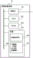
Fig. 3 is a block diagram of the HMD.
Fig. 4 is a block diagram of a VR service server.
Fig. 5 is a block diagram of an MR assistance server.
Fig. 6A is a diagram showing an example of a conventional three-dimensional virtual reality display (a diagram showing a state in which a 3DAR object overlaps a real object).
Fig. 6B is a diagram showing a three-dimensional virtual reality display (first overlap elimination display example) according to the first embodiment.
Fig. 6C is a diagram showing a three-dimensional virtual reality display (second overlap elimination display example) according to the first embodiment.
Fig. 6D is a diagram showing a three-dimensional virtual reality display (third overlap elimination display example) according to the first embodiment.
Fig. 7A is a flowchart of the MR experiencing program of the first embodiment.
Fig. 7B is a diagram showing an example of a determination algorithm for the degree of overlapping of volumes.
Fig. 8 is a flowchart of the VR service server of the first embodiment.
Fig. 9 is a flowchart of the MR assistance server of the first embodiment.
Fig. 10A is a diagram showing an example of a conventional three-dimensional virtual reality display (a diagram showing a state in which a real object is positioned closer to a 3DAR object).
Fig. 10B is a diagram showing a three-dimensional virtual reality display (fourth overlap elimination display example) according to the second embodiment.
Fig. 11 is a flowchart of the MR experiencing program of the second embodiment.
FIG. 12A is a diagram showing an example of a conventional three-dimensional virtual reality display (a diagram showing a state in which a 3DAR object is superimposed on a real object)
Fig. 12B is a diagram showing an example of the three-dimensional virtual reality display according to the third embodiment (an example of processing of the transparent portion).
Fig. 12C is a diagram showing an example of three-dimensional virtual reality display according to the third embodiment (an example in which VR images are replaced).
FIG. 13 is a diagram showing a 3DAR object table.
Fig. 14 is a flowchart of the MR experiencing program of the third embodiment.
Fig. 15 is a diagram showing another example of the three-dimensional virtual reality display according to the third embodiment.
Fig. 16 is a block diagram of an MR assist server according to the fourth embodiment.
Fig. 17 is a flowchart showing a flow of the three-dimensional virtual reality display process according to the fourth embodiment.
Detailed Description
Hereinafter, embodiments of the present invention will be described with reference to the drawings. In all the drawings, the same components and steps are denoted by the same reference numerals, and redundant description thereof is omitted.
In the present embodiment, a three-dimensional virtual real object (hereinafter referred to as a "3DAR object", and in the drawings, referred to as a "3D-ARO") generated by CG (Computer Graphics) is synthesized with a three-dimensional real space image (hereinafter referred to as a "real space image") obtained by capturing an image of a real space with a distance measuring camera and displayed. In the present embodiment, the distance measuring camera 20 is used to integrally configure the camera and the distance sensor for measuring the distance, but the camera may be configured in combination with a separate distance sensor such as an ultrasonic distance meter.
When a 3DAR object is superimposed on a three-dimensional real space image obtained by capturing an image in real space and displayed, an image to be displayed on a far side from a viewpoint generates a shaded region due to an image to be displayed on a near side. As an image processing method for expressing the mask region, there is mask processing.
A mixed real space (MR) image obtained by combining an AR image and a background image in real space is used for game, maintenance work, sales promotion, and the like. In order to synthesize an AR image, for example, a subject called an AR marker is captured from a real space image, and an AR image associated with the AR marker is superimposed on the subject area. Since an HMD (head mounted display) in which a camera and a display are integrated is often used as hardware for performing three-dimensional virtual reality display, an embodiment for implementing the present invention in the HMD will be described below.
[ first embodiment ]
A first embodiment will be described with reference to fig. 1 to 9.
(Structure of three-dimensional virtual reality display System)
Fig. 1 is a schematic diagram of a three-dimensional virtual reality display system according to a first embodiment.
In fig. 1, the MR experiencer 2 wears the HMD2a on the head and views the MR space 1. Likewise, the MR experiencer 3 wears the HMD3a on the head, viewing the MR space 1.
The HMD2a, 3a perform wireless communication connection by transmitting and receiving wireless LAN signals 1b, 2b,3b to and from the access point 1a, respectively.
The access point 1a is disposed in the MR space 1. The access point 1a is connected to a network 7 outside the MR space 1, and communicates with each of the HMDs 2a and 3a, and the VR service server 8 and the MR support server 9 provided in the network 7.VR (Virtual Reality) refers to Virtual Reality space.
In real space, MR non-experience persons 4a and 4b exist. Further, a vase 5a and a window 5b are present as a part of the background of the real space. The 3DAR object 6 is a three-dimensional AR object of a car.
The MR space 1 is a space in which sales promotion of a vehicle is assumed, and is not limited to a space of a specific MR experiencer, and MR experiences can be performed simultaneously by a plurality of persons like the MR experiencers 2 and 3. The MR experiencer 3 is a commodity commentator, and may be a case where the same 3DAR object 6 as the MR experiencer 2 is viewed from a different direction, or may be an independent visitor viewing a different 3DAR object than the MR experiencer 2. By presenting the car as the sales target as the 3DAR object 6, the propaganda person does not need to show expensive real objects (cars) nor a large space for showing a plurality of cars. In the MR space 1, entrants such as MR non-experiences 4a and 4b may exist in addition to the MR experiences 2 and 3. The MR non-experiencers 4a,4b are family members of the MR experiencers 2,3, or waiting visitors who are to undergo an MR experience later, or the like.
The MR non-experiencers 4a,4b do not view the 3DAR objects 6 and movement within the MR space 1 is not restricted. Thus, as with MR non-experiencer 4b, it may be co-located with 3DAR object 6.
Fig. 2 is an external view of the HMDs 2a and 3a as an example of the three-dimensional virtual reality display device. The HMD2a is a video see-through HMD. Since HMD3a has the same structure as HMD2a, the description thereof is omitted. The HMD2a includes a range camera 20 with parallax and a display 22. The HMD2a captures a foreground image with the range camera 20, and displays the 3DAR object 6 drawn by CG or the like for image synthesis captured by the range camera 20 on the display 22 arranged in front of the MR examiner 2.
The range camera 20 includes a left camera 20a and a right camera 20b, and is a range camera for measuring a distance to an object being photographed. The display 22 is a flat display having a shutter 23 on its inner side. When the left-eye image and the right-eye image are alternately displayed on the display 22, the shutter 23 opens and closes in synchronization with the display on the display 22. That is, the display device operates such that the left half of the display 22 is opened and the right half is closed when displaying the image for the left eye, and the left half of the display 22 is closed and the right half is opened when displaying the image for the right eye. Thus, HMD2a supports three-dimensional display. The MR experiencer 2 alternately views the display image with only one eye in synchronization with the displayed image.
Furthermore, the HMD2a includes a processor 24 and wearing housings 25a and 25b. The HMD2a is worn on the head with the wearing frames 25a,25 b.
The image of the real space in front captured by the left camera 20a and the right camera 20b is displayed on the display 22, and the MR examiner 2 views the image of the real space. In addition, the display 22 maps the 3DAR object 6 superimposed on the real space image. At this time, the image of the AR object for the left eye is superimposed on the image captured by the left camera 20a, and the image of the AR object for the right eye is superimposed on the image captured by the right camera 20b and displayed on the display 22, and the 3DAR object 6 is stereoscopically (three-dimensionally) displayed as if it were located at a predetermined distance in the real space.
The HMD2a displays a real object in real space, and in fig. 1, reflects the front-rear relationship between the distances of the MR non-experience person 4b, the vases 5a, the windows 5b, and the 3DAR object 6. For example, when a part of the real object (MR non-experience person 4 b) is located before a part of the 3DAR object 6, occlusion processing for processing the rendering data of the 3DAR object 6 is performed so that the part of the 3DAR object 6 appears to be occluded by the part of the real object (MR non-experience person 4 b).
(Block diagram of three-dimensional virtual reality display device)
Fig. 3 is a block diagram of the HMD2 a. In fig. 3, the same reference numerals are attached to the same portions as those in fig. 2. In fig. 3, the processor 24 is a portion enclosed by a broken line, and the processor 24 is connected to the left camera 20a, the right camera 20b, the display 22, the shutter 23, the speaker 26, and the microphone 27.
The processor 24 includes a camera processor 240, an orientation sensor 241, a gyro sensor 242, an acceleration sensor 243, a wireless communicator 244, a CPU245 (corresponding to a main processor), a RAM246, an image RAM247, a Flash ROM (FROM) 248, and an internal bus 249, and the respective elements are connected to each other via the internal bus 249.
The wireless communicator 244 selects an appropriate process from among mobile communications such as 4G and 5G and several types of communication processes such as wireless LAN, and connects the HMD2a to the network 7 via the access point 1 a.
FROM248 includes a basic program 250, MR experience program 251.CPU245 deploys these processing programs to RAM246 and executes them. Further, FROM248 stores data necessary for executing the processing program. FROM248 may be a nonvolatile storage medium other than a Flash ROM (memory).
Further, the CPU245 stores image data transmitted to the display 22 in the image RAM247 and then reads the image data.
The camera processor 240 executes a distance calculation process to the subject (corresponding to a real object) in the real space image based on the images captured by the left camera 20a and the right camera 20b, and adds distance data of the subject in the real space image to the real space image. In the present specification, the "real space image" refers to an image only, and data to which distance data is added is referred to as "real space image data".
The sensor group such as the orientation sensor 241, the gyro sensor 242, and the acceleration sensor 243 is used to know the position of the HMD2a and the shooting direction of the range-finding camera 20 (used as the line of sight of the MR examiner 2 wearing the HMD2 a).
The HMD2a may include a part or all of the processing executed by the VR service server 8 and the MR assistance server 9 described below.
Fig. 4 is a block diagram of the VR service server 8. The VR service server 8 includes a network interface (network IF) 81 such as a wired LAN, a CPU82, a RAM83, and a storage 84, which are connected to each other via an internal bus 85.
The storage 84 is not limited to the Flash ROM, and may be combined with a hard disk drive or the like. The storage 84 stores VR services 86. The CPU82 deploys the VR service program 86 to the RAM83 and executes it.
Further, the storage 84 holds VR data 87 of 3DAR objects and the like. The VR data 87 is data necessary for executing the VR service 86.
As the VR data 87, VR (visual Reality) image data may be included in addition to the 3DAR object. The VR image data is an image in which the entire real space image of the MR examinees 2 and 3 is replaced, and the MR examinees 2 and 3 can obtain an experience of viewing the 3DAR object 6 while feeling as if they are in another space provided by the VR image data.
Fig. 5 is a block diagram of the MR assistance server 9. The MR support server 9 includes a network IF91 such as a wired LAN, a CPU92, a RAM93, and a storage 94, which are connected to each other via an internal bus 95.
The storage 94 is not limited to the Flash ROM, and may be combined with a hard disk drive or the like. The storage 94 includes an MR assist program 96 as a processing program. The CPU92 deploys the MR assist program 96 to the RAM93 and executes it.
Further, the storage 94 stores a background object image 97 and a real object image 98. Which are the data required to perform the MR-assisted procedure 96.
The background object image 97 and the real object image 98 are data for the user to perform the MR experience, and when the data corresponds to a plurality of users, there is data allocated for each user.
The real object image 98 is data for detecting a region in which motion is present by time difference or the like from a real space image received from the HMD2a and recognizing one region as a real object. Further, it is also possible to detect what the real object is, for example, whether or not the real object is a human, based on the shape of the real object or the like.
The background object image 97 is data of a background image obtained by removing a region of a real object from the real space image, and is data of a region of the real space image where there is no motion. In the removed real object region, a background image is obtained by interpolating data when no real object appears in the region from the real space image traced back in time. More specifically, since the background object image 97 is located behind the real object image 98, the background object located further behind the real object image 98 is not captured at a certain time, that is, in the same frame (target frame) of the three-dimensional real space image composed of a plurality of frames. Then, the MR support program 96 recognizes the real object image 98 from the target frame, and extracts the background object image 97 from the other frame in which it is not reflected, thereby generating the background object image 97.
(displaying the resulting image with three-dimensional virtual reality)
Fig. 6A to 6D are diagrams illustrating a three-dimensional virtual reality display method. Fig. 6A is a diagram showing an example of a conventional three-dimensional virtual reality display (a diagram showing a state in which a 3DAR object overlaps a real object), fig. 6B is a diagram showing a three-dimensional virtual reality display (a first overlap elimination display example) according to the first embodiment, fig. 6C is a diagram showing a three-dimensional virtual reality display (a second overlap elimination display example) according to the first embodiment, and fig. 6D is a diagram showing a three-dimensional virtual reality display (a third overlap elimination display example) according to the first embodiment. Fig. 6A to 6C correspond to the AREA (AREA) surrounded by the broken line shown in fig. 1. As shown in fig. 1, the MR non-experiencer 4b as a real object and the 3DAR object 6 are located at the same distance relationship and overlap each other in the line of sight of the HMD2 a. Here, the "distance relationship" refers to a distance relationship in the same line-of-sight direction of the MR examiner 2, which is the wearer of the HMD2a, with the HMD2a as a base point. And does not include the same distance relationship as the distance between MR experiences 2 but different line-of-sight directions.
Fig. 6A is an image after occlusion processing of an overlapping MR non-experiencer 4b (real object) and a 3DAR object 6. The upper part of the MR non-experiencer 4b located in front of the 3DAR object 6 is displayed and the lower part of the MR non-experiencer 4b located behind the 3DAR object 6 is not displayed. As a result, the MR non-experiencer 4b (such as a person whose upper body is supported or growing on the hood of the vehicle) appears from the 3DAR object 6, and the MR non-experiencer 4b becomes an unnatural image that hinders the recognition of the 3DAR object 6. Therefore, in this embodiment, the processing shown in fig. 6B or 6C is performed.
In fig. 6B, 6C, occlusion processing is not performed with real objects (MR non-experiencers 4B) and 3DAR objects 6 located at positions at the same distance. Instead, in the region of the real object (MR non-experiencer 4 b), the background object image 10 cut out from the background image is inserted, and occlusion processing is performed using the background object image 10 and the 3DAR object 6. The background object image 10 is typically located at a greater distance from the same line of sight than the 3DAR object 6, enabling the 3DAR object 6 to be displayed intact, and also displaying the background (e.g., the vases 5 a) hidden by the real objects (MR non-experiencers 4 b), so a natural MR experience can be achieved. The above is the process of fig. 6B (first overlap elimination display).
In fig. 6C, in addition to fig. 6B, the image of the real object (MR non-experiential person 4B) is moved (dodged) to a position that does not interfere with the recognition of the 3DAR object 6 (second overlap elimination display). The image 11 of fig. 6C is a real object (MR non-experiencer 4 b) after movement. When the real object (MR non-experiencer 4 b) is a person such as a child of the MR experiencers 2 and 3 who is to pay attention to at any time, the real object is not displayed, the 3DAR object 6 and the real object (MR non-experiencer 4 b) are simultaneously viewed, and an unnatural image obtained by occlusion processing is not displayed, and thus the MR experience is characterized in that the immersion feeling is maintained. Here, when the real object (the MR non-experience person 4 b) is moved, the distances between the far and near positions generally differ in the same line of sight from the MR experience person 2. In this case, the scale of the real object (the MR non-experiential person 4 b) is reduced or increased in accordance with the distance from the MR experiential person 2, and thus the real object can be viewed in a natural size.
Fig. 6D shows an example in which the real space image is replaced with VR image data 6a (third overlap elimination example). When the VR image data 6a is located on the back surface of the 3DAR object 6, the 3DAR object 6 is displayed with the VR image 6a as the background. In addition, depending on the scene of the car promotion, when switching from the image of fig. 6B or 6C to the display shown in fig. 6D, an image in which various backgrounds are combined with the 3DAR object 6 can be displayed, and the user can view the 3DAR object 6 in various scenes. When switching from the video of fig. 6B or 6C to the background video of fig. 6D, the video may be gradually synthesized and changed, or processed by a scribing process.
(flow chart)
Fig. 7A is a flowchart of the MR experience program 251 of the first embodiment. The MR experiencer 2 starts the MR experience program 251 stored in the HMD2a (S101), and logs in to the VR service server 8 and the MR auxiliary server 9. The following describes the operation in the HMD2a executing the MR experience program 251 in order of steps. In addition, the following description will be given taking an example of processing in a case where the MR non-experience person 4b as a real object overlaps or does not overlap with the 3DAR object 6 of the vehicle.
The HMD2a starts shooting with the camera (S102). The distance data to the real object is added to the image captured by the range camera 20. Shooting with a camera can be performed, for example, in synchronization with a camera shooting cycle, by shooting a moving image at 30fps (frame per second) to generate three-dimensional real space image data in which a plurality of frames are arranged in time series, capturing the shot image, and thereafter, the steps can be performed.
The HMD2a transmits the three-dimensional real space image data to the MR assist server 9 via the wireless communicator 244 (S103). The MR assistance server 9 separates the image of the appearing real object (MR non-experiencer 4 b) and the image of the background object (e.g., vase 5a, window 5 b) from the image of the real space as described later.
Furthermore, the HMD2a transmits a request for transmission of the rendering data (included in the VR data 87) of the 3DAR object 6 to the VR service server 8 (S104).
The HMD2a receives at least one or more, preferably all, real object image data (including real object images and distance data thereof) extracted from the real space image from the MR assistance server 9 (S105), and receives rendering data of a 3DAR object (in this example, the 3DAR object 6) and VR image data from the VR service server 8 (S106).
The HMD2a compares the distance between the real object image (including the image of the MR non-human subject 4b and the distance data thereto) viewed from the HMD2a on the same line of sight with reference to the HMD2a and the 3DAR object 6, which are three-dimensionally superimposed between each real object (MR non-human subject 4 b) and the 3DAR object 6.
In the case where the real object and the three-dimensional 3DAR object 6 are located at the same distance on the same line of sight, the volume of the real object overlaps with the volume of the 3DAR object. Therefore, when the occlusion processing is performed without considering the overlapping of the volumes, for example, even if the occlusion processing is successful for the near position of the 3DAR object 6 and the surface of the real object, the distance relationship with the surface of the real object is not properly processed at the far position of the 3DAR object 6, and the unnatural display of the real object may appear suddenly from the 3DAR object 6.
In the present embodiment, the conventional occlusion processing or overlap elimination display processing is selected according to the degree of overlap between the real object and the volume of the 3DAR object 6.
Then, the HMD2a performs occlusion processing with the real object and the 3DAR object (S108) at a distance at which the volume of the real object and the volume of the 3DAR object 6 do not overlap (S107: separation).
On the other hand, when the HMD2a performs the overlap elimination display processing when the volume of the real object (MR non-experience person 4 b) and the volume of the 3DAR object overlap each other by a distance (S107: overlap).
An example of the determination algorithm in step S107 will be described with reference to fig. 7B. Fig. 7B is a diagram showing an example of a determination algorithm of the volume overlapping degree. For convenience of explanation, the display surface of the HMD2a is a surface parallel to the vertical direction. Then, with 1 point of the display 22, for example, the upper left corner of the display 22 as the origin, real three-dimensional coordinates are defined using the two-dimensional coordinates x-y plane of the screen and the z-axis orthogonal thereto. Thus, the z-x plane is a horizontal plane, and the z-axis represents the distance in the near-far direction of the line of sight viewed from the HMD2 a.
In the example of fig. 7B, when the real object is located on the front surface of the HMD2a, the z-axis value matches the distance from the HMD2a to the MR non-experience person 4B. Since the MR non-experiencer 4b is observed with the range camera 20, the MR non-experiencer 4b has a position P on the line of sight L from the observer R (x R ,z R ) May be represented by the intersection of the line of sight L and the surface of the MR non-experiencer 4b opposite to the HMD2 a.
On the other hand, for a 3DAR object 6, its shape is defined by the three-axis coordinates of (s, t, u) of the three-dimensional image system. When an AR marker appears in real space, a 3DAR object 6 is displayed superimposed on it. Thus, if the origin(s) of the 3DAR object 6 is made 0 ,t 0 ,u 0 ) Three-dimensional coordinates (x) with AR markers l ,y m ,z n ) Overlap, then(s) can be 0 ,t 0 ,u 0 ) Is converted into (x) l ,y m ,z n ). For convenience of explanation, it is assumed that there is no deviation between the stu coordinate system and the xyz coordinate system in the rotation direction of each axis, and that the s-axis coincides with the x-axis, the t-axis coincides with the y-axis, and the u-axis coincides with the z-axis.
In the processor 24, if there is only one point constituting the 3DAR object 6 on the line of sight L of the HMD2a, the point is selected as the farthest point P n In the presence of a plurality of dots, e.g. P 1 、……、P n-2 、P n-1 、P n In the case of (3), the point farthest from the HMD2a, that is, the point having the largest z-axis value is selected as the farthest point P n . In addition, the point P at which the value of the z-axis is minimum 1 Is the closest point.
Then, the intersection point P between the line of sight L and the MR non-experiencer 4b is defined R Three-dimensional coordinates (x) of R ,y R ,z R ) And the most distant point P of the 3DAR object 6 n Coordinate (x) of (2) ARn ,y ARn ,z ARn ) (wherein, x in this example) R =x ARn ,y R =y ARn ) A comparison is made. If z is R >z ARn It is determined that there is no volumetric overlap of the real object with the 3DAR object 6 (state 1). If z is R And less than zar, it is determined that the real object and the 3DAR object 6 have a volume overlapping portion (state 2).
Then, the HMD2a requests the MR support server 9 for data of a background object image (corresponding to the background object image 10 in fig. 6B) corresponding to the region of the real object (MR non-experiencer 4B) (S109), and receives it (S110). Upon receipt, the HMD2a hides the real object (MR non-experiencer 4 b) with background object images 10 and 3DAR objects 6 (first eliminating the overlay display). In addition, the HMD2a intercepts real objects (MR non-experiencer 4 b) and displays them in a place that does not overlap with the 3DAR object 6, and embeds background object images 10 in the area where the real objects (MR non-experiencer 4 b) actually exist (second elimination overlap display).
When VR image data of the background is received together with the drawing data of the 3DAR object 6 in S106, the background object image of the real object is replaced with a VR image in steps S107 and S108, and a combining process such as an occlusion process and a movement of the real object is performed using the VR image of the background, the 3DAR object, and the real object in S108. Here, although the present example shows a configuration in which processing for synthesizing the display images of the HMD2a is performed in the HMD2a, the location for performing the synthesizing processing is not limited to this, and processing may be performed by a server connected via a network, a smartphone or tablet that performs cooperative connection, or the like, as described later.
The HMD2a checks whether or not the steps of S107 to S111 have been executed for all real objects overlapping with the 3DAR object 6, and returns to S107 when a real object remains (S112: no). On the other hand, when the HMD2a completes processing of all real objects (yes in S112), the processed image is displayed on the display 22 of the HMD2a (S113).
If the MR experience program 251 of the HMD2a is not completed yet, the steps from S103 onward are continued in the next camera cycle (S114: no). When the MR experience program 251 of the HMD2a is completed (yes in S114), the above processing is terminated.
Fig. 8 is a flowchart of the VR service routine 86. Upon receiving the login request of the registered MR experience 2, login processing is executed (S121).
When the VR service server 8 receives a request for transmission of drawing data of a 3DAR object 6 from HMD2a (S122), it generates the requested drawing data of the 3DAR object (S123). The drawing data of the 3DAR object is data (object file) which 3D draws the 3DAR object 6 according to the distance between the HMD2a and the 3DAR object and the visual line direction of the HMD2a included in the request for transmitting the drawing data of the 3DAR object, and the drawing data is updated according to the movement of the HMD2a and/or the change in the visual line. Further, the influence of reflection and/or shading may be added to the image as drawing data in accordance with the direction of the sun and the light source such as illumination.
The VR service server 8 transmits the generated rendering data to the HMD2a (S124).
The VR service server 8 continues the processing from steps S122 to S124 until the end condition of the VR service program 86 is satisfied, such as the MR experiencer 2 logs out or the MR experience program 251 ends (S125: no).
When the end condition of the VR service routine 86 is satisfied (S125: yes), the VR service server 8 ends the series of processing.
Fig. 9 is a flowchart of the MR assist procedure 96.
The MR assistance server 9 processes the login request of the registered MR experiencer 2 (S131).
The MR support server 9 receives the real space image data from the HMD2a (S132), recognizes the real object image (S133), extracts the real object image data, and obtains a background image. The background image is updated every time the real space image is received (S134).
The MR assist server 9 transmits the real object image data to the HMD2a (S135). When the MR support server 9 receives the request for transmitting the background object image (S136), it transmits the background object image data to the HMD2a (S137).
The MR support server 9 continues the processing from steps S132 to S137 until the end condition of the MR support program 96 is satisfied, such as the MR experiencer 2 logs out or the MR experience program 251 ends (S138: no).
When the end condition of the MR supporting program 96 is satisfied (S138: yes), the MR supporting server 9 ends the series of processing.
According to the present embodiment, when a real object and a 3DAR object 6 overlap on the same line of sight of an MR examiner, occlusion processing is performed when the volume of the real object and the volume of the 3DAR object 6 are separated to such an extent that they do not overlap, and overlap elimination processing is performed without performing occlusion processing when the two overlap to such an extent that they are close to each other, so that the real object and the 3DAR object 6 do not appear to overlap unnaturally. Thus, the immersion of the MR experience can be improved.
In addition, according to the present embodiment, in an open space where a third person (MR non-experiencer) who does not perform the MR experience exists, the shape of the 3DAR object 6 is not affected by the third person, so that the MR experiencer can accurately recognize the 3DAR object 6 and perform the MR experience.
[ second embodiment ]
A second embodiment of the present invention will be described with reference to fig. 10A, 10B, and 11. Fig. 10A is a diagram showing an example of a conventional three-dimensional virtual reality display (a diagram showing a state in which a real object is positioned closer to the 3DAR object 6). Fig. 10B is a diagram showing a three-dimensional virtual reality display (fourth overlap elimination display example) according to the second embodiment.
As shown in fig. 10A, the MR non-experiencer 4b and the 3DAR object 6 as real objects are located at the same distance, and the other MR non-experiencer 4c as real objects is located in front of the 3DAR object 6, and they both overlap in the line of sight of the HMD2a, preventing the 3DAR object 6 from being viewed.
In fig. 10B, the MR non-experiencer 4B located on the rear side of the 3DAR object 6 is replaced with the background object image 10 as in the first embodiment. On the other hand, the other MR non-experiencer 4c is deleted and a 3DAR object 6 is configured. Further, in a residual region where the 3DAR objects 6 do not overlap in the region from which the MR non-experience person 4c is deleted, an image corresponding to the residual region is extracted from the panoramic image of the other frame to generate a foreground image, and the foreground image is embedded in the residual region. The 3DAR object 6 and background object image 10 correspond to the MR non-experiencer 4b, and the 3DAR object 6 and foreground image 11a correspond to the other MR non-experiencer 4 c. A process of covering the real object images of the MR non-experiencer 4b and the other MR non-experiencers 4c with the background object image 10 and the foreground images 11a and 3DAR objects 6 to hide them is performed (fourth overlap elimination example). As a result, the 3DAR object 6 as a whole can be viewed.
Fig. 11 is a flowchart of the MR experiencing program 251 of the second embodiment.
The difference from the flowchart of fig. 7 is in the distance comparison of the step of S150.
In S150, it is determined whether the distance between the real object and the 3DAR object 6 is "behind and apart" or "close to and in front", the former case is where the real object and the 3DAR object 6 are used for occlusion processing (S108), and the latter case is where a request for transmitting a background object image and a foreground image is made (S151) and received (S152). Then, the real object image is hidden with the background object image, the 3DAR object 6, and the foreground image (S153). In the above example, the MR non-experiencer 4b and the other MR non-experiencer 4c are treated as if they did not exist.
As described above, according to the second embodiment, the removal of real objects that obstruct the observation of the 3DAR object 6 can be performed even if the real objects are located closer to the 3DAR object 6, with the same features as those of the first embodiment.
[ third embodiment ]
A third embodiment will be described with reference to fig. 12A to 15B.
Fig. 12A is a diagram showing an example of a conventional three-dimensional virtual reality display (a diagram showing a state in which a 3DAR object and a real object are superimposed). Fig. 12B is a diagram showing an example of the three-dimensional virtual reality display according to the third embodiment (a processing example of the transparent portion). Fig. 12C is a diagram showing an example of three-dimensional virtual reality display according to the third embodiment (an example in which VR images are replaced). In fig. 12A to 12C, the MR examiner 2 is experiencing a situation as if sitting in the driver's seat of the vehicle. A dashboard 60, a front window 61, a rear view mirror 62, a steering wheel 63, and the like are displayed as 3DAR objects. The MR non-experiencers 4d,4e (real objects) overlap the front window 61 and can be seen across the front window 61. The dashboard 60, front window 61, rear view mirror 62, and steering wheel 63 are parts that constitute the 3DAR object 6 of the vehicle. In this example, the 3DAR object 6 as one virtual real object is divided into a plurality of parts of the virtual real object, and a flag for specifying the type of occlusion processing is added to each part. Since the dashboard 60, the rear view mirror 62, and the steering wheel 63 are non-transparent areas of the 3DAR object 6, respectively, a non-transparent area mark is attached. On the other hand, because the front window 61 is a transparent area of the 3DAR object 6, a transparent area flag is attached.
Fig. 12A shows a representation in the case where no occlusion processing is performed, and the MR non-viewers 4d and 4e and the 3DAR object 6 are unnaturally overlapped with each other.
Fig. 12B shows the result of the occlusion processing. In the third embodiment, the Occlusion Flag (Occlusion Flag) described in fig. 13 is set for the drawing data of the 3DAR object 6 in the front window 61, and the processing for replacing the real object overlapping the front window 61 with the 3DAR object 6 is prohibited, and the Occlusion processing is performed using the real object and the 3DAR object 6. As a result, the MR non-experiences 4d,4e are observed across the front window 61. At this time, when the distance between the MR non-experience 4d and the 3DAR object 6 is close and the MR non-experience 4d is displayed behind the front window 61, the MR non-experience 4d (real object) is reduced in size and displayed at a distance generally separated from the MR non-experience 4d as in fig. 12B in the case of the same expression as the MR non-experience 4B (real object) in fig. 6A. Since the MR non-experience person 4e is located further than the instrument panel (3 DAR object) 60, the steering wheel 63 (3 DAR object), and the 3DAR object 6 as a vehicle body, the front window 61 is treated as a transparent part, and the occlusion processing is performed in a distance relationship with the other parts.
Fig. 12C shows a case where the background image in real space is replaced with the VR image 6 b. Although the dashboard 60, the steering wheel 63, and the VR image 6b are shielded, the front window 61 is a transmissive or semi-transmissive 3DAR object, and can observe the VR image 6b located far from the line of sight, and can perform an experience as if it were located in a virtual place provided by the VR image.
FIG. 13 is a table 100 of an example of a 3DAR object. The 3DAR object is identified by the CONTENTS ID, and a plurality of 3DAR objects (AR objects 1 to 7, etc.) can be combined into a related object. Each 3DAR object includes "Data id" inherent to the 3DAR object, "Title" for making it easy for a user such as an MR experiencer to understand, and "occupancy Flag", "3DImage Data".
"00", "01", "10" are defined for "Occlusion Flag". When the value of "Occlusion Flag" is "00", occlusion processing is performed according to the distance between the real object and the 3DAR object. A Flag that the value of "occupancy Flag" is "00" corresponds to the non-transparent part Flag.
When the value of "occupancy Flag" is "01", if the distance between the real object and the 3DAR object is close, the real object is replaced with a background object, and the 3DAR object is not hidden, and the Flag that the value of "occupancy Flag" is "01" corresponds to the non-transparent part Flag.
When the value of "Occlusion Flag" is "10", the 3DAR object is regarded as transparent regardless of the distance as in the front window 61 of fig. 12B, and Occlusion processing is performed using the 3DAR object and the real object that are far from the front window 61. A Flag that the value of "occupancy Flag" is "10" corresponds to the transparent part Flag. The 3DAR object remote from the front window 61 may be part of the 3DAR object 6 of the motor vehicle, for example the bonnet, or may be another 3DAR object different from the 3DAR object 6 of the motor vehicle, for example a 3DAR object of another motor vehicle.
Fig. 14 is a flowchart of the MR experiencing program 251 of the third embodiment.
The difference from the flowchart of fig. 7 is that steps S160 and S161 are added.
HMD2a checks in S160 for "occupancy Flag" of the 3DAR object, and as illustrated in fig. 13, makes the processing different according to "occupancy Flag".
If "Occlusion Flag" is "00", HMD2a performs Occlusion processing in S108 in accordance with the relationship between the distance between the real object and the 3DAR object (this processing is described with reference to fig. 15).
If the "occupancy Flag" is "10", HMD2a performs processing to make it look transparent even at a distance closer than the real object, as a transparent object such as the front window 61 shown in fig. 12, in S161. After that, the process proceeds to S107.
If "occupancy Flag" is "01", in S107, HMD2a compares the distance between the real object and the 3DAR object, and performs different processing for the case of separation and the case of proximity or overlap of distance.
Fig. 15 is an example of an image in the case where "occupancy Flag" is "00" is applied. Fig. 15 is a situation where a real object 4f is playing near the sea (3 DAR objects with a beach 64 and a sea surface 65 present). In fig. 15, "occupancy Flag" of the sea surface 65 is set to "00". Even if half of the person as the real object 4f appears from the sea surface 65, there is no unnatural feeling. Therefore, the occlusion processing may be performed in relation to the distance between the sea surface 65 and the real object 4 f.
As described above, according to the third embodiment, the same features as those of the first embodiment are provided, and the occlusion processing corresponding to the features of the 3DAR object can be applied.
[ fourth embodiment ]
A fourth embodiment will be described with reference to fig. 16 and 17. Fig. 16 is a block diagram of the MR assist server 9 of the fourth embodiment. The MR support server 9 according to the fourth embodiment holds 3DAR object & VR image data 900, real space image data 901, and display image data 902 in the storage 94.
The MR assistance server 9 of the fourth embodiment holds the 3DAR object & VR image data 900 received from the VR service server 8, and the real space image data 901 received from the HMD2a, as instructed by the HMD2 a.
Further, the MR support server 9 recognizes and extracts an object located on the far side (far side) in the near-far direction in the line of sight of the real object image 98 as a background object from the real space image data 901, and generates a background object image 97.
Further, the MR support server 9 performs occlusion processing or the like on the real object image 98 and the 3DAR object & VR image data 900 to obtain display image data 902 synthesized with the real space image. The display image data 902 is transmitted to the HMD2a and displayed on the display 22 of the HMD2 a. When VR image data of the background is received together with image data of 3DAR objects, the VR image data is accumulated in 3DAR object & VR image data 900.
The MR support server 9 includes a program for replacing a background image of a real object with VR image data, performing occlusion processing using a VR image of the background, a 3DAR object, and the real object, and performing synthesis processing such as movement of the real object.
Fig. 17 is a flowchart of the MR assist routine 96 according to the fourth embodiment.
The MR assistance server 9 processes the login request of the registered MR experiencer 2 (S131). Further, the MR support server 9 receives the real space image data from the HMD2a (S132).
The MR assistance server 9 transmits a transmission request of the rendering data of the 3DAR object to the VR service server (S140). With respect to the requested 3DAR object, the user decides what AR content to synthesize in HMD2a and receives an indication of the transmission of rendering data for the 3DAR object accordingly.
The MR support server 9 recognizes the real object from the real space image data received in S132 (S133), and updates the background image from the received real space image data (S134).
The MR assistance server 9 receives rendering data of the 3DAR object and VR image (there is also a case where no VR image is received) data (S141).
The MR assistance server 9 detects the overlap of the real object and the 3DAR object, and compares the distances of the 2 objects (S142). When the volumes are separated to such an extent that they do not overlap (S142: separation), occlusion processing is performed using a real object and a 3DAR object (S143).
On the other hand, when the images are superimposed (S142: superimposition), the MR support server 9 generates data of a background object image from the background image (S144), and performs a process of covering the real object with the background object image and the 3DAR object and hiding the real object (S145).
The MR support server 9 checks whether or not the steps from S142 to S145 have been performed for all real objects overlapping with the 3DAR object, and if a real object remains (no in S146), returns to S142.
When the processing has been completed for all real objects (yes in S146), the MR support server 9 transmits the processed images to the HMD2a as display image data (S147).
The MR assist server 9 confirms the end of the procedure, and if not (S138: no), proceeds with the steps from S142. When the processing is ended (S138: YES), the series of processing is ended.
According to the fourth embodiment, the same features as those of the first embodiment are provided, and most of the MR experience processing is performed by the MR assistance server 9 of high performance, and the processing for reducing the HMD2a and the like can be provided to make the implementation method flexible.
The present invention is not limited to the embodiments described above with reference to fig. 1 to 17, and a part of the structure of one embodiment may be replaced with another embodiment. In addition, the structure of another embodiment can be added to the structure of one embodiment. All of them fall within the scope of the present invention, and the numerical values, messages, and the like appearing in the text and in the drawings are only examples, and the effects of the present invention are not impaired even if different numerical values, messages, and the like are used.
In addition, a part or all of the functions of the invention and the like can be realized by hardware by designing in an integrated circuit or the like, for example. The operation program may be interpreted and executed by a microprocessor unit, a CPU, or the like, and may be implemented by software. Further, the scope of software implementation is not limited, and both hardware and software may be used.
Description of the reference numerals
1: MR space
1 a: access point
1 b: wireless LAN signal
2,3: MR experiencer
2a,3a :HMD
2b, 3b: wireless LAN signal
4a,4b,4c,4d, 4e: MR non-experiencer
4 f: real object
5 a: flower vase
5 b: window with a window pane
6: 3DAR object
6 a: VR image data
6 b: VR images
7: network
8: VR service server
9: MR auxiliary server
10: background object image
11: image of a person
11 a: foreground image
20: distance measuring camera
20 a: left video camera
20 b: right camera
22: display device
23: shutter
24: processor with a memory having a plurality of memory cells
25a, 25b: frame for mounting
26: loudspeaker
27: microphone (CN)
60: instrument panel
61: front window
62: rear-view mirror
63: steering wheel
64: beach sand
65: sea surface
82 :CPU
83 :RAM
84: storing
85: internal bus
86: VR service program
87: VR data
91: network IF
92 :CPU
93 :RAM
94: storing
95: internal bus
96: MR assisted procedure
97, 98: background object image
100: watch (A)
240: processor for camera
241: orientation sensor
242: gyroscope sensor
243: acceleration sensor
244: wireless communication device
245 :CPU
246 :RAM
247: image RAM
249: internal bus
250: basic procedure
251: MR experience program
900: 3DAR object & VR image data
901: real space image data
902: displaying image data
L: sight line
PR: intersection point
Pn: farthest point
P1: the closest point.
Claims (11)
1. A three-dimensional virtual reality display apparatus, comprising:
a camera that captures a real space and outputs an image of a real object existing in the real space;
a distance sensor that measures a distance from an observer of the real space to the real object;
a display; and
a processor that causes the display to display a three-dimensional virtual reality object,
the processor compares a distance from the observer to display the three-dimensional virtual real object with a distance from the observer to the real object when the real object is positioned on a line of sight of the observer to observe the three-dimensional virtual real object, and performs overlap elimination display processing of displaying the three-dimensional virtual real object on the line of sight and not displaying the real object image on the line of sight when the real object overlaps the three-dimensional virtual real object.
2. The three-dimensional virtual reality display apparatus of claim 1, wherein:
the processor determines that the real object overlaps with the three-dimensional virtual real object when the real object is located at the same distance as or before a farthest point farthest in a far-near direction along the line of sight among points constituting the three-dimensional virtual real object.
3. The three-dimensional virtual reality display apparatus of claim 2, wherein:
the processor performs, when the real object is located farther from the line of sight than the farthest point, occlusion processing for displaying the real object image behind the three-dimensional virtual real object, and displays the real object image.
4. The three-dimensional virtual reality display apparatus of claim 2, wherein:
the processor deletes the real object image from a three-dimensional real space image obtained by capturing an image of the real space by the camera when the real object is located at the same distance as the farthest point or at a position closer to the farthest point, and embeds and displays a background object image generated based on the three-dimensional real space image in a region where the deletion is performed.
5. The three-dimensional virtual reality display apparatus of claim 4, wherein:
the processor moves the deleted real object image to a position in the three-dimensional real space image that avoids the line of sight for display.
6. The three-dimensional virtual reality display apparatus of claim 2, wherein:
and a processor configured to display a three-dimensional virtual reality object superimposed on a three-dimensional virtual space image prepared in advance when the real object is located at the same distance as or closer to the farthest point.
7. The three-dimensional virtual reality display apparatus of claim 2, wherein:
the processor deletes the real object image from a three-dimensional real space image obtained by capturing the real space by the camera, superimposes the three-dimensional virtual real object on the three-dimensional real space image from which the real object is deleted, and embeds and displays a foreground image generated based on the three-dimensional real space image in a residual region obtained by deleting the real object image from the three-dimensional real space image, when the real object is located at the same distance as or before the closest point in the far-near direction along the line of sight among the points constituting the three-dimensional virtual real object.
8. The three-dimensional virtual reality display apparatus of claim 1, wherein:
the three-dimensional virtual reality object is attached with a marker for controlling occlusion processing for the three-dimensional virtual reality object,
the processor controls execution of occlusion processing and the like between the three-dimensional virtual reality object and the real object image in correspondence with the marker.
9. The three-dimensional virtual reality display apparatus of claim 8, wherein:
the three-dimensional virtual reality object includes a non-transparent region and a transparent region,
the marks include a non-transparent area mark attached to the non-transparent area and a transparent area mark attached to the transparent area,
the processor performs the above-described overlap elimination display processing on a portion of the three-dimensional virtual reality object to which the non-transparent region marker is attached, and performs display corresponding to a distance between another portion of the three-dimensional virtual reality object or another three-dimensional virtual reality object and the real object when the other portion of the three-dimensional virtual reality object or another three-dimensional virtual reality object and the real object are positioned in a line of sight through which the real object is observed through the transparent region, or performs display corresponding to a distance to the real object when only the real object is positioned in the line of sight, on a transparent region of the three-dimensional virtual reality object to which the transparent region marker is attached.
10. A head-mounted display, characterized in that:
a three-dimensional virtual reality display device according to any one of claims 1 to 9 is mounted.
11. A three-dimensional virtual reality display method is characterized by comprising the following steps:
a step of acquiring three-dimensional real space image data obtained by adding a distance from an observer of a real space to a real object existing in the real space to a three-dimensional real space image generated by capturing the real space;
comparing a distance from the observer to display a three-dimensional virtual reality object with a distance to the real object obtained based on the three-dimensional real space image data, in a case where the real object is located on a line of sight of the observer to observe the three-dimensional virtual reality object; and
when the real object and the three-dimensional virtual real object overlap each other, performing overlap elimination display processing for displaying the three-dimensional virtual real object on the visual line and not displaying the real object image on the visual line.
Applications Claiming Priority (1)
| Application Number | Priority Date | Filing Date | Title |
|---|---|---|---|
| PCT/JP2020/032034 WO2022044124A1 (en) | 2020-08-25 | 2020-08-25 | 3d virtual-reality display device, head-mounted display, and 3d virtual-reality display method |
Publications (1)
| Publication Number | Publication Date |
|---|---|
| CN115968486A true CN115968486A (en) | 2023-04-14 |
Family
ID=80354888
Family Applications (1)
| Application Number | Title | Priority Date | Filing Date |
|---|---|---|---|
| CN202080103495.4A Pending CN115968486A (en) | 2020-08-25 | 2020-08-25 | Three-dimensional virtual reality display device, head-mounted display and three-dimensional virtual reality display method |
Country Status (5)
| Country | Link |
|---|---|
| US (1) | US20230230333A1 (en) |
| EP (1) | EP4207084A4 (en) |
| JP (1) | JPWO2022044124A1 (en) |
| CN (1) | CN115968486A (en) |
| WO (1) | WO2022044124A1 (en) |
Families Citing this family (1)
| Publication number | Priority date | Publication date | Assignee | Title |
|---|---|---|---|---|
| JP2024047648A (en) * | 2022-09-27 | 2024-04-08 | 株式会社Jvcケンウッド | Display device, display method, and program |
Family Cites Families (9)
| Publication number | Priority date | Publication date | Assignee | Title |
|---|---|---|---|---|
| JP4227561B2 (en) * | 2004-06-03 | 2009-02-18 | キヤノン株式会社 | Image processing method and image processing apparatus |
| DE102007045835B4 (en) * | 2007-09-25 | 2012-12-20 | Metaio Gmbh | Method and device for displaying a virtual object in a real environment |
| JP4933406B2 (en) * | 2007-11-15 | 2012-05-16 | キヤノン株式会社 | Image processing apparatus and image processing method |
| JP2013101528A (en) * | 2011-11-09 | 2013-05-23 | Sony Corp | Information processing apparatus, display control method, and program |
| JP2015087909A (en) * | 2013-10-30 | 2015-05-07 | キヤノン株式会社 | Information processing system, information processing device, information processing server, information processing method and program |
| JP2016122392A (en) | 2014-12-25 | 2016-07-07 | キヤノンマーケティングジャパン株式会社 | Information processing apparatus, information processing system, control method and program of the same |
| US10943399B2 (en) * | 2017-08-28 | 2021-03-09 | Microsoft Technology Licensing, Llc | Systems and methods of physics layer prioritization in virtual environments |
| US10679410B2 (en) * | 2018-09-14 | 2020-06-09 | Facebook Technologies, Llc | Display opacity control for preventing view occlusion in artificial reality |
| US11651567B2 (en) * | 2018-12-13 | 2023-05-16 | Maxell, Ltd. | Display terminal, display control system and display control method |
-
2020
- 2020-08-25 CN CN202080103495.4A patent/CN115968486A/en active Pending
- 2020-08-25 US US18/022,745 patent/US20230230333A1/en active Pending
- 2020-08-25 JP JP2022544936A patent/JPWO2022044124A1/ja active Pending
- 2020-08-25 WO PCT/JP2020/032034 patent/WO2022044124A1/en unknown
- 2020-08-25 EP EP20951378.7A patent/EP4207084A4/en active Pending
Also Published As
| Publication number | Publication date |
|---|---|
| EP4207084A4 (en) | 2024-05-01 |
| JPWO2022044124A1 (en) | 2022-03-03 |
| WO2022044124A1 (en) | 2022-03-03 |
| US20230230333A1 (en) | 2023-07-20 |
| EP4207084A1 (en) | 2023-07-05 |
Similar Documents
| Publication | Publication Date | Title |
|---|---|---|
| EP3115873A1 (en) | Head-mounted display device and computer program | |
| US8179423B2 (en) | Image display system, an image display method, a coding method, and a printed matter for stereoscopic viewing | |
| JP7244541B2 (en) | Augmented reality display device and augmented reality display method | |
| JP2017185988A (en) | Device for vehicle, program for vehicle, and filter design program | |
| CN111602100A (en) | Method, device and system for providing alternative reality environment | |
| US11972532B2 (en) | Display terminal, display control system and display control method | |
| KR20170107432A (en) | Three-dimensional map display system | |
| JP2023065502A (en) | Mixed reality display device and mixed reality display method | |
| CN113253845A (en) | View display method, device, medium and electronic equipment based on eye tracking | |
| TW201919390A (en) | Display system and method thereof | |
| JP2022183213A (en) | Head-mounted display | |
| CN115968486A (en) | Three-dimensional virtual reality display device, head-mounted display and three-dimensional virtual reality display method | |
| CN113170090A (en) | Head-mounted display device | |
| JP4724476B2 (en) | Information processing method and apparatus | |
| US11297296B2 (en) | Display control apparatus, program, and display control method | |
| JP6898264B2 (en) | Synthesizers, methods and programs | |
| WO2022086580A1 (en) | Dynamic resolution of depth conflicts in telepresence | |
| JP5319728B2 (en) | Parallax image generation device, display device, parallax image generation method, parallax image generation program, and recording medium recording the same | |
| JPH08101924A (en) | Picture composition method | |
| JP2023174066A (en) | Image processing apparatus, image processing method, and program | |
| CN117193530A (en) | Intelligent cabin immersive user experience method and system based on virtual reality technology | |
| EP3511898A1 (en) | A method and a system for displaying a reality view | |
| JP2023046339A (en) | Display control device, head-up display apparatus and display control method | |
| JP2024015868A (en) | Head-mounted display and image display method | |
| KR20210042143A (en) | Methods for providing image representation of at least a portion of the vehicle environment, computer program products and driver assistance systems |
Legal Events
| Date | Code | Title | Description |
|---|---|---|---|
| PB01 | Publication | ||
| PB01 | Publication | ||
| SE01 | Entry into force of request for substantive examination | ||
| SE01 | Entry into force of request for substantive examination |